HARBOR FREIGHT 56624 Pittsburgh 3 Ton
Heavy Duty Floor Jack Owner's Manual

http://www.harborfreight.com
[email protected]
SAFETY
![]()

IMPORTANT SAFETY INFORMATION
![]() WARNING
WARNING
Failure to heed these markings may result in personal injury and/or property damage.
- Study, understand, and follow all instructions before operating this device.
- Do not exceed rated capacity.
- Use only on hard, level surfaces.
- Lifting device only. Immediately after lifting, support the vehicle with appropriate means.
- Do not move or dolly the vehicle while on the jack.
- No alterations shall be made to this product.
- Never work on, under or around a load supported only by this device.
- Do not adjust safety valve.
- Wear ANSI-approved safety goggles and heavy-duty work gloves during use.
- Keep clear of load while lifting and lowering.
- Lower load slowly.
- Apply parking brake and chock tires before lifting vehicle.
- Lift vehicle only at manufacturer recommended locations.
- Inspect before every use; do not use if parts are loose or damaged.
- Do not use for aircraft purposes.
- The warnings, precautions, and instructions discussed in this manual cannot cover all possible conditions and situations that may occur. The operator must understand that common sense and caution are factors, which cannot be built into this product, but must be supplied by the operator.
IMPORTANT! Before first use:
Check hydraulic fluid level and fill to 1/4 below the fill port as needed – see instructions on page 5. Thoroughly test the Jack for proper operation. If it does not work properly, bleed air from its hydraulic system – see instructions on page 5.
![]() SAVE THESE INSTRUCTIONS.
SAVE THESE INSTRUCTIONS.
Setup – Before Use:
![]() Read the ENTIRE IMPORTANT SAFETY INFORMATION section at the beginning of this manual including all text under subheadings therein before set up or use of this product.
Read the ENTIRE IMPORTANT SAFETY INFORMATION section at the beginning of this manual including all text under subheadings therein before set up or use of this product.
Note: For additional information regarding the parts listed in the following pages, refer to Parts List and Diagram 7 on page 2.
Tool Set Up
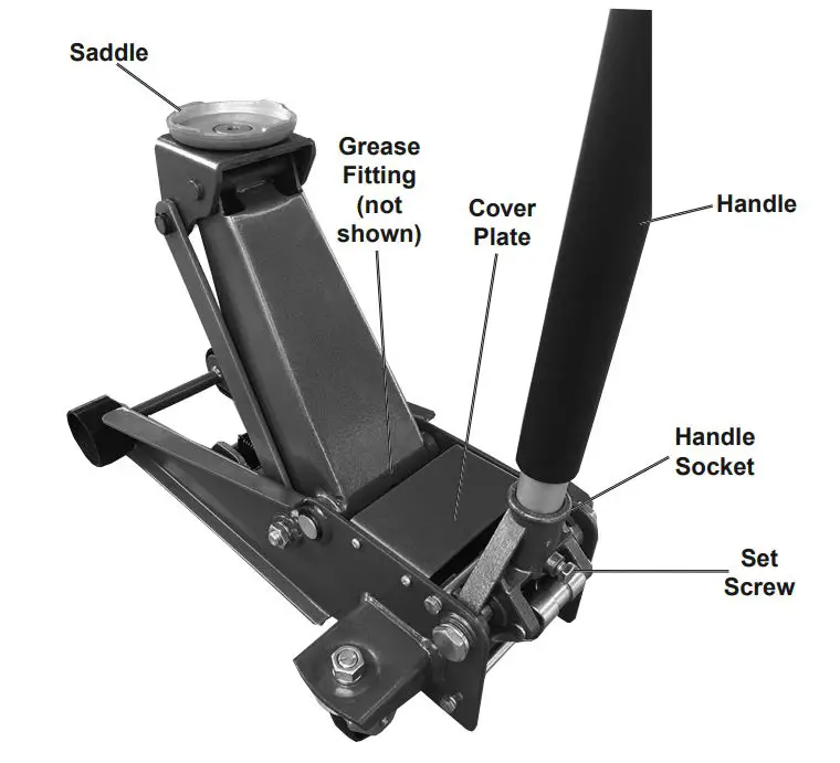
Attaching the Handle
- Attach the Upper Handle to the Lower Handle.
- Loosen the Set Screw and insert the assembled Handle into the Handle Socket.
- Tighten the Set Screw.
Functions
Operating Instructions
![]() Read the ENTIRE IMPORTANT SAFETY INFORMATION section at the beginning of this manual including all text under subheadings therein before set up or use of this product.
Read the ENTIRE IMPORTANT SAFETY INFORMATION section at the beginning of this manual including all text under subheadings therein before set up or use of this product.
Bleeding
BEFORE EACH USE OR IF JACK PERFORMANCE DECREASES, check for excessive air and proper hydraulic fluid level in Jack. If Jack appears not to be working properly, it may be necessary to purge its hydraulic system of excessive air as follows:
- Turn handle counter clockwise to open Release Valve.
- Remove four screws holding on pump cover.
- Remove Oil Fill Plug and top off hydraulic oil.
- Apply pressure to saddle and quickly pump handle several times.
- Check Oil Fill Hole again and top off with hydraulic oil if necessary.
- Replace the Oil Fill Plug and turn handle clockwise to close Release Valve.
- Test several times for proper operation before attempting to lift a load.
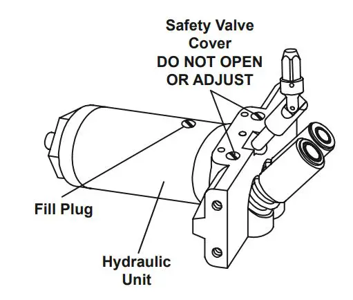
Adding Hydraulic Fluid
- Remove Cover Plate and Fill Plug.
- Add high grade hydraulic fluid (sold separately) slowly until the fluid reaches 1/4 below the top of the Fill Port.
Note: Do not touch the Handle when adding hydraulic fluid. - Assemble Fill Plug, close Cover Plate, and reinstall the screws.
Lifting
![]() WARNING
WARNING
Park vehicle on a flat, level, solid, surface safely away from oncoming traffic. Turn off the vehicle’s engine. Place the vehicle’s transmission in “PARK” (if automatic) or in its lowest gear (if manual). Set the vehicle’s emergency brake. Then, chock the wheels that are not being lifted.
- Slowly twist the Handle counter clockwise to lower the Jack. Once the Jack is fully lowered, twist the Handle firmly clockwise.
- Carefully position the Jack’s Saddle under the vehicle manufacturer’s recommended lifting point. (See vehicle manufacturer’s owner’s manual for location of frame lifting point.)
- Pump the Handle until the top of the Saddle has nearly reached the vehicle’s lifting point. Position the Saddle directly under the vehicle’s lifting point.
- To lift the vehicle, pump the Handle. Use smooth, full strokes.
- Select matching jack stands (sold separately) of appropriate capacity. Set the jack stands to the same height according to the manufacturer’s instructions, making sure they lock securely into position.
- Position the jack stands’ saddles under the vehicle manufacturer’s recommended support points.
Ensure that the vehicle support points are fully seated in the saddles of both jack stands. Use a matched pair of jack stands per vehicle to support one end only. - Slowly twist the Handle counter clockwise to lower the vehicle onto the jack stands’ saddles.
- Once the vehicle is fully seated on the jack stands, continue slowly lowering the Jack until it is completely lowered.
- Remove the Jack and store safely out of the way.
Lowering
- Carefully remove all tools, parts, etc. from under the vehicle.
- Position the Jack’s Saddle under the lifting point. Turn the Release Knob firmly clockwise and raise vehicle high enough to clear the jack stands.
- Carefully remove the jack stands.
- Slowly turn the Release Knob counter clockwise to lower the vehicle onto the ground.
- Lower the Jack completely. Store the Jack indoors out of children’s reach.
Maintenance and Servicing
![]() Procedures not specifically explained in this manual must be performed only by a qualified technician.
Procedures not specifically explained in this manual must be performed only by a qualified technician.
![]() WARNING
WARNING
TO PREVENT SERIOUS INJURY FROM TOOL FAILURE: Do not use damaged equipment. If abnormal noise or vibration occurs, have the problem corrected before further use.
Cleaning, Maintenance, and Lubrication
- BEFORE EACH USE, inspect the general condition of the Jack. Check for:
• loose hardware,
• misalignment or binding of moving parts,
• cracked or broken parts,
• any condition that may affect its safe operation. - BEFORE EACH USE, thoroughly test the Jack for proper operation prior to its actual use. If the Jack appears not to be working properly, follow Bleeding instructions on page 4.
- ONCE A MONTH, lubricate the Grease Fitting with a grease gun.
- AT LEAST ONCE EVERY THREE YEARS, change the hydraulic fluid:
a. With the Jack fully lowered, remove the Cover Plate and Fill Plug.
b. Tip the Jack over to allow the old hydraulic fluid to drain out completely. Dispose of the old hydraulic fluid in accordance with local regulations.
c. With the Jack upright, completely fill the Hydraulic Unit with high grade hydraulic fluid until the fluid is 1/4 below the top of the Fill Port.
d. Turn the Release Knob counter clockwise to open the Release Valve.
e. Pump the Handle or Foot Pedal up and down quickly several times to purge air from the system.
f. Recheck fluid level and re-fill as needed.
g. Replace the Fill Plug and Cover Plate. - AFTER EACH USE, wipe with a clean cloth. Store the Jack indoors out of children’s reach.
![]()
Troubleshooting
![]() WARNING
WARNING
TO PREVENT SERIOUS INJURY: Use caution when troubleshooting a malfunctioning jack. Stay well clear of the supported load. Completely resolve all problems before use. If the solutions presented in the Troubleshooting guide do not solve the problem, have a qualified technician inspect and repair the jack before use.
After the jack is repaired: Test it carefully without a load by raising and lowering it fully, checking for proper operation, BEFORE RETURNING THE JACK TO OPERATION.
DO NOT USE A DAMAGED OR MALFUNCTIONING JACK!
PLEASE READ THE FOLLOWING CAREFULLY
THE MANUFACTURER AND/OR DISTRIBUTOR HAS PROVIDED THE PARTS LIST AND ASSEMBLY DIAGRAM IN THIS MANUAL AS A REFERENCE TOOL ONLY. NEITHER THE MANUFACTURER OR DISTRIBUTOR MAKES ANY REPRESENTATION OR WARRANTY OF ANY KIND TO THE BUYER THAT HE OR SHE IS QUALIFIED TO MAKE ANY REPAIRS TO THE PRODUCT, OR THAT HE OR SHE IS QUALIFIED TO REPLACE ANY PARTS OF THE PRODUCT. IN FACT, THE MANUFACTURER AND/OR DISTRIBUTOR EXPRESSLY STATES THAT ALL REPAIRS AND PARTS REPLACEMENTS SHOULD BE UNDERTAKEN BY CERTIFIED AND LICENSED TECHNICIANS, AND NOT BY THE BUYER. THE BUYER ASSUMES ALL RISK AND LIABILITY ARISING OUT OF HIS OR HER REPAIRS TO THE ORIGINAL PRODUCT OR REPLACEMENT PARTS THERETO, OR ARISING OUT OF HIS OR HER INSTALLATION OF REPLACEMENT PARTS THERETO.
Record Product’s Serial Number Here:_______________________
If product has no serial number, record month and year of purchase instead.
Some parts are listed and shown for illustration purposes only, and are not available individually as replacement parts. Specify UPC 193175365774 when ordering parts.
Parts List and Assembly Diagram – Jack
Limited 90 Day Warranty
Harbor Freight Tools Co. makes every effort to assure that its products meet high quality and durability standards, and warrants to the original purchaser that this product is free from defects in materials and workmanship for the period of 90 days from the date of purchase. This warranty does not apply to damage due directly or indirectly, to misuse, abuse, negligence or accidents, repairs or alterations outside our facilities, criminal activity, improper installation, normal wear and tear, or to lack of maintenance. We shall in no event be liable for death, injuries to persons or property, or for incidental, contingent, special or consequential damages arising from the use of our product. Some states do not allow the exclusion or limitation of incidental or consequential damages, so the above limitation of exclusion may not apply to you. THIS WARRANTY IS EXPRESSLY IN LIEU OF ALL OTHER WARRANTIES, EXPRESS OR IMPLIED, INCLUDING THE WARRANTIES OF MERCHANTABILITY AND FITNESS. To take advantage of this warranty, the product or part must be returned to us with transportation charges prepaid. Proof of purchase date and an explanation of the complaint must accompany the merchandise. If our inspection verifies the defect, we will either repair or replace the product at our election or we may elect to refund the purchase price if we cannot readily and quickly provide you with a replacement. We will return repaired products at our expense, but if we determine there is no defect, or that the defect resulted from causes not within the scope of our warranty, then you must bear the cost of returning the product. This warranty gives you specific legal rights and you may also have other rights which vary from state to state.
![]()
10/2/50 Amp 12 Volt Battery Charger/Starter
Owner’s Manual & Safety Instructions

Save This Manual Keep this manual for the safety warnings and precautions, assembly, operating, inspection, maintenance and cleaning procedures. Write the product’s serial number in the back of the manual near the assembly diagram (or month and year of purchase if product has no number).
Keep this manual and the receipt in a safe and dry place for future reference.
Visit our website at: http://www.harborfreight.com
Email our technical support at: [email protected]
When unpacking, make sure that the product is intact and undamaged. If any parts are missing or broken, please call 1-888-866-5797 as soon as possible.
Copyright© 2012 by Harbor Freight Tools®. All rights reserved.
No portion of this manual or any artwork contained herein may be reproduced in any shape or form without the express written consent of Harbor Freight Tools.
Diagrams within this manual may not be drawn proportionally. Due to continuing improvements, actual product may differ slightly from the product described herein.
Tools required for assembly and service may not be included.
WARNINGS
Read this material before using this product.
Failure to do so can result in serious injury.
SAVE THIS MANUAL.
Important Safety Instructions
- SAVE THESE INSTRUCTIONS –
This manual contains important safety and operating instructions for this battery charger. - Do not expose charger to rain or snow.
- Use of an attachment not recommended or sold by the battery charger manufacturer may result in a risk of fire, electric shock, or injury to persons.
- To reduce risk of damage to electric plug and cord, pull by plug rather than cord when disconnecting charger.
- An extension cord should not be used unless absolutely necessary. Use of improper extension cord could result in a risk of fire and electric shock.
If an extension cord must be used, make sure:
a. That pins on plug of extension cord are the same number, size, and shape as those of plug on charger;
b. That extension cord is properly wired and in good electrical condition; and
c. That wire size is large enough for AC ampere rating of charger as specified in Table A. - Do not operate charger with damaged cord or plug – replace the cord or plug immediately.
- Do not operate charger if it has received a sharp blow, been dropped, or otherwise damaged in any way; take it to a qualified serviceman.
- Do not disassemble charger; take it to a qualified serviceman when service or repair is required. Incorrect reassembly may result in a risk of electric shock or fire.
- To reduce risk of electric shock, unplug charger from outlet before attempting any maintenance or cleaning. Turning off controls will not reduce this risk.
- WARNING – RISK OF EXPLOSIVE GASES.
a. WORKING IN VICINITY OF A LEAD-ACID BATTERY IS DANGEROUS. BATTERIES GENERATE EXPLOSIVE GASES DURING NORMAL BATTERY OPERATION. FOR THIS REASON, IT IS OF UTMOST IMPORTANCE THAT YOU FOLLOW THE INSTRUCTIONS EACH TIME YOU USE THE CHARGER.
b. To reduce risk of battery explosion, follow these instructions and those published by battery manufacturer and manufacturer of any equipment you intend to use in vicinity of battery. Review cautionary marking on these products and on engine. - PERSONAL PRECAUTIONS
a. Consider having someone close enough by to come to your aid when you work near a lead-acid battery.
b. Have plenty of fresh water and soap nearby in case battery acid contacts skin, clothing, or eyes.
c. Wear complete eye protection and clothing protection. Avoid touching eyes while working near battery.
d. If battery acid contacts skin or clothing, wash immediately with soap and water.
If acid enters eye, immediately flood eye with running cold water for at least 10 minutes and get medical attention immediately.
e. NEVER smoke or allow a spark or flame in vicinity of battery or engine.
f. Be extra cautious to reduce risk of dropping a metal tool onto battery. It might spark or short-circuit battery or other electrical part that may cause explosion.
g. Remove personal metal items such as rings, bracelets, necklaces, and watches when working with a lead-acid battery. A leadacid battery can produce a short-circuit current high enough to weld a ring or the like to metal, causing a severe burn.
h. Use charger for charging a LEAD-ACID battery only. It is not intended to supply power to low voltage electrical system other than in a starter-motor application. Do not use battery charger for charging dry-cell batteries that are commonly used with home appliances.
These batteries may burst and cause injury to persons and damage to property.
i. NEVER charge a frozen battery. - PREPARING TO CHARGE
a. If necessary to remove battery from vehicle to charge, always remove grounded terminal from battery first. Make sure all accessories in the vehicle are off, so as not to cause an arc.
b. Be sure area around battery is well ventilated while battery is being charged.
c. Clean battery terminals. Be careful to keep corrosion from coming in contact with eyes.
d. Add distilled water in each cell until battery acid reaches level specified by battery manufacturer. Do not overfill. For a battery without removable cell caps, such as valve regulated lead acid batteries, carefully follow manufacturer’s recharging instructions.
e. Study all battery manufacturer’s specific precautions while charging and recommended rates of charge.
f. Charge battery initially at lowest rate. - CHARGER LOCATION
a. Locate charger as far away from battery as DC cables permit.
b. Never place charger directly above battery being charged; gases from battery will corrode and damage charger.
c. Never allow battery acid to drip on charger when reading electrolyte specific gravity or filling battery.
d. Do not operate charger in a closed-in area or restrict ventilation in any way.
e. Do not set a battery on top of charger. - DC CONNECTION PRECAUTIONS
a. Connect and disconnect DC output clips only after removing AC cord from electric outlet.
Never allow clips to touch each other.
b. Attach clips to battery and chassis as indicated in 15(e), 15(f), and 16(b) through 16(d). - FOLLOW THESE STEPS WHEN BATTERY IS INSTALLED IN VEHICLE. A SPARK NEAR BATTERY MAY CAUSE BATTERY EXPLOSION.
TO REDUCE RISK OF A SPARK NEAR BATTERY:
a. Position AC and DC cables to reduce risk of damage by hood, door, or moving engine part.
b. Stay clear of fan blades, belts, pulleys, and other parts that can cause injury to persons.
c. Check polarity of battery posts. POSITIVE (POS, P, +) battery post usually has larger diameter than NEGATIVE (NEG, N,–) post.
d. Determine which post of battery is grounded (connected) to the chassis. If negative post is grounded to chassis (as in most vehicles), see (e). If positive post is grounded to the chassis, see (f).
e. For negative-grounded vehicle, connect POSITIVE (RED) clip from battery charger to POSITIVE (POS, P, +) ungrounded post of battery. Connect NEGATIVE (BLACK) clip to vehicle chassis or engine block away from battery. Do not connect clip to carburetor, fuel lines, or sheet-metal body parts. Connect to a heavy gauge metal part of the frame or engine block.
f. For positive-grounded vehicle, connect NEGATIVE (BLACK) clip from battery charger to NEGATIVE (NEG, N, –) ungrounded post of battery. Connect POSITIVE (RED) clip to vehicle chassis or engine block away from battery.
Do not connect clip to carburetor, fuel lines, or sheet-metal body parts. Connect to a heavy gauge metal part of the frame or engine block.
g. When disconnecting charger, disconnect AC cord, remove clip from vehicle chassis, and then remove clip from battery terminal.
h. See operating instructions for length of charge information. - FOLLOW THESE STEPS WHEN BATTERY IS OUTSIDE VEHICLE. A SPARK NEAR THE BATTERY MAY CAUSE BATTERY EXPLOSION.
TO REDUCE RISK OF A SPARK NEAR BATTERY:
a. Check polarity of battery posts. POSITIVE (POS, P, +) battery post usually has a larger diameter than NEGATIVE (NEG, N, –) post.
b. Attach at least a 24-inch-long 6-gauge (AWG) insulated battery cable to NEGATIVE (NEG, N, –) battery post.
c. Connect POSITIVE (RED) charger clip to POSITIVE (POS, P, +) post of battery.
d. Position yourself and free end of cable as far away from battery as possible – then connect NEGATIVE (BLACK) charger clip to free end of cable.
e. Do not face battery when making final connection.
f. When disconnecting charger, always do so in reverse sequence of connecting procedure and break first connection while as far away from battery as practical.
g. A marine (boat) battery must be removed and charged on shore. To charge it on board requires equipment specially designed for marine use. - Wear ANSI-approved splash-resistant safety goggles and heavy-duty rubber work gloves whenever connecting, disconnecting, or working near battery.
Battery acid can cause permanent blindness. - Do not use Start setting to charge batteries. Use to jump start only.
- Maintain labels and nameplates on the charger.
These carry important safety information.
If unreadable or missing, contact Harbor Freight Tools for a replacement. - This product is not a toy.
Keep it out of reach of children. - Unplug the Battery Charger from its electrical outlet before connecting its cables to a battery, or performing any inspection, maintenance, or cleaning procedures.
- Although this charger has an automatic cut off; do NOT depend solely on automatic cut off.
Leaving charger unattended can result in fire and property damage. - Use this charger with flooded lead-acid or AGM batteries only.
When charging a maintenance-free battery, always monitor the progress of the charge by viewing the Charge Meter.
Do not overcharge a maintenance-free battery.
DO NOT USE WITH GEL BATTERIES. - Do not attempt to charge non-rechargeable or defective batteries.
- Do not charge more than one battery at one time.
- Have your charger serviced by a qualified repair person using only identical replacement parts.
This will ensure that the safety of the charger is maintained. - Do not use charger while you are tired or under the influence of drugs, alcohol or medication.
A moment of inattention while operating charger may result in serious personal injury. - Before moving charger, disconnect power supply and battery, then allow charger to cool.
- People with pacemakers should consult their physician(s) before use. Electromagnetic fields in close proximity to heart pacemaker could cause pacemaker interference or pacemaker failure.
In addition, people with pacemakers should:
• Avoid operating alone.
• Properly maintain and inspect to avoid electrical shock.
• Properly ground power cord. Ground Fault Circuit
Interrupter (GFCI) should also be implemented
– it prevents sustained electrical shock. - The warnings, precautions, and instructions
discussed in this instruction manual cannot cover all possible conditions and situations that may occur. It must be understood by the operator that common sense and caution are factors which cannot be built into this product, but must be supplied by the operator.
SAVE THESE INSTRUCTIONS
Grounding and Ac power cord connection Instructions
Charger should be grounded to reduce risk of electric shock. Charger is equipped with an electric cord having an equipment-grounding conductor and a grounding plug. The plug must be plugged into an outlet that is properly installed and grounded in accordance with all local codes and ordinances.
DANGER – Never alter AC cord or plug provided – if it will not fit outlet, have proper outlet installed by a qualified electrician. Improper connection can result in a risk of an electric shock.
CAUTION – Risk of Fire or Electric Shock.
Connect battery charger directly to grounding receptacle (three-prong). An adapter should not be used with battery charger.
Specifications

*Amperage is only present when the unit is connected to a battery or in START mode.
Operation Instructions
Read the ENTIRE IMPORTANT SAFETY INFORMATION section at the beginning of this manual including all text under subheadings therein before set up or use of this product.
TO PREVENT SERIOUS INJURY:
DO NOT PLUG IN CHARGER UNTIL DIRECTED TO DO SO.
Controls

Wiring connection:
This indicates that the cables are connected improperly.
Immediately disconnect the cables and connect them properly to prevent damage to the battery.
Charge Status:
This will light up red when the power is connected.
This will light up green when the battery is fully charged.
This is disabled in start mode.
Setting switch:
Use this to switch between charging and start modes and change the output amperage.
Battery Type switch:
Use this to set the battery type:
- Set to Regular for flooded and maintenance-free batteries.
- Set to AGM for Absorbed Glass Mat batteries.
WARNING! TO PREVENT EXPLOSION:
DO NOT USE WITH GEL BATTERIES.
Charge Meter (10 amp charge mode only):
Initial charge current to the battery is at maximum.
Charge current to the battery is reduced.
Charge current to the battery is minimal and the green LED is on.
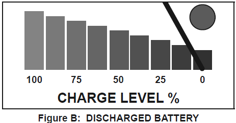
Sometimes conditions such as a cold battery, a sulfated battery, or a deeply discharged lead calcium battery may cause Charge Meter to read near a full charge when charging process is only beginning.
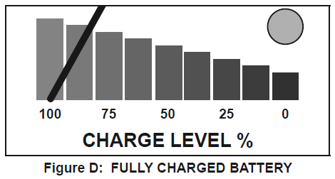
Note: The Charge Meter shows the amount of current being drawn from the charger. It does not show what the charger is capable of delivering. When the battery is fully charged and registering 100% on the Charge Meter,
a small charge will continue to move from the charger to the battery. If the charger is not disconnected from the battery, eventually heat build up will cause the battery acid to boil and overcharge the battery causing damage to the battery. Monitor battery charging progress constantly and if battery gets warm, stop charging it immediately.
Preparing to Charge
WARNINGS:
Use this charger only on flooded lead-acid batteries.
Other batteries may be damaged or may overheat, leak, or catch fire.
TO PREVENT SERIOUS INJURY:
Wear ANSI-approved splash-resistant safety goggles and heavy-duty rubber work gloves whenever connecting, disconnecting, or working near battery.
Battery acid can cause permanent blindness.
- If necessary to remove battery from vehicle to charge, always remove grounded terminal from battery first. Make sure all accessories in the vehicle are off, so as not to cause an arc.
- Make sure area around battery is well ventilated while battery is being charged.
- Clean battery terminals. Be careful to keep corrosion from coming in contact with eyes.
- Add distilled water in each cell until battery acid reaches level specified by battery manufacturer.
Do not overfill. For a battery without removable cell caps, such as valve regulated lead acid batteries, carefully follow manufacturer’s recharging instructions. - Study all battery manufacturer’s specific precautions while charging and recommended rates of charge.
- Charge battery initially at lowest rate.
- A marine (boat) battery must be removed and charged on shore. To charge it on board requires equipment specially designed for marine use.
SHORTED BATTERIES – will read on Charge Meter as a high end peg at beginning of charging process. If after 5-10 minutes, needle does not move off high end, the battery probably has a short circuit. Unplug charger and discontinue use.
Have battery checked by a qualified technician.
COLD BATTERIES – begin charging at a low rate, increase as battery reaches a normal temperature, then rate will decrease normally.
DO NOT CHARGE A FROZEN BATTERY.
BATTERIES WITH HYDROMETER EYE:
Do not depend on hydrometer eye to determine battery charge level.
Charger Location
- Locate charger as far away from battery as DC cables permit.
- Never place charger directly above battery being charged; gases from battery will corrode and damage charger.
- Never allow battery acid to drip on charger when reading electrolyte specific gravity or filling battery.
- Do not operate charger in a closed-in area or restrict ventilation in any way.
- Do not set a battery on top of charger.
Charging Battery Installed in Vehicle
WARNINGS:
A spark near battery may cause battery explosion.
To reduce risk of a spark near battery follow these instructions exactly.
TO PREVENT SERIOUS INJURY:
Wear ANSI-approved splash-resistant safety goggles and heavy-duty rubber work gloves whenever connecting, disconnecting, or working near battery.
Battery acid can cause permanent blindness.
WARNING! Do not use Start setting to charge batteries. Use to jump start only.
- Position AC and DC cables to reduce risk of damage by hood, door, or moving engine part.
- Stay clear of fan blades, belts, pulleys, and other parts that can cause injury to persons.
- Check polarity of battery posts. POSITIVE (POS, P, +) battery post usually has larger diameter than NEGATIVE (NEG, N,–) post.
- Determine which post of battery is grounded (connected) to the chassis. If negative post is grounded to chassis (as in most vehicles), see 5.
If positive post is grounded to the chassis, see 6. - For negative-grounded vehicle, connect POSITIVE (RED) clip from battery charger to POSITIVE (POS, P, +) ungrounded post of battery.
Connect NEGATIVE (BLACK) clip to vehicle chassis or engine block away from battery.
Do not connect clip to carburetor, fuel lines, or sheet-metal body parts. Connect to a heavy gauge metal part of the frame or engine block.
NOTICE: If the Reverse connection indicator lights, the cables are connected improperly.
Immediately disconnect the cables and connect them properly to prevent damage to the battery. - For positive-grounded vehicle, connect NEGATIVE (BLACK) clip from battery charger to NEGATIVE (NEG, N, –) ungrounded post of battery. Connect POSITIVE (RED) clip to vehicle chassis or engine block away from battery.
Do not connect clip to carburetor, fuel lines, or sheet-metal body parts. Connect to a heavy gauge metal part of the frame or engine block.
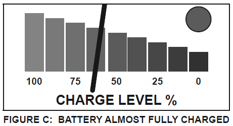
Note: If the charger cycles between maximum charge level and a lower charge level when first connected, then the battery may be fully charged or nearly fully charged. Further charging may not be needed.
If charging is attempted, charge at a lower rate and carefully monitor charge level to avoid battery damage. - Set Battery Type switch according to battery type:
• Set to Regular for flooded and maintenance-free batteries.
• Set to AGM for Absorbed Glass Mat batteries.
WARNING! TO PREVENT EXPLOSION:
DO NOT USE WITH GEL BATTERIES. - Set Setting switch to 2A Trickle Charge or 10A Quick Charge.
WARNING! Do not use 50A Emergency Engine Start function for charging. - After switches are set, plug in charger.
- Monitor the charging process.
The Charge Complete indicator will light up and blink when the battery is fully charged. - When disconnecting charger, disconnect AC cord, remove clip from vehicle chassis, and then remove clip from battery terminal.
- After use clean, then store the charger indoors out of children’s reach.
Charging Battery Outside Vehicle
WARNINGS:
A spark near battery may cause battery explosion.
To reduce risk of a spark near battery follow these instructions exactly.
TO PREVENT SERIOUS INJURY:
Wear ANSI-approved splash-resistant safety goggles and heavy-duty rubber work gloves whenever connecting, disconnecting, or working near battery.
Battery acid can cause permanent blindness.
WARNING! Do not use Start setting to charge batteries. Use to jump start only.
- Check polarity of battery posts. POSITIVE (POS, P, +) battery post usually has a larger diameter than NEGATIVE (NEG, N, –) post.
- Attach at least a 24-inch-long 6-gauge (AWG) insulated battery cable to NEGATIVE (NEG, N, –) battery post.
- Connect POSITIVE (RED) charger clip to POSITIVE (POS, P, +) post of battery.
- Position yourself and free end of cable as far away from battery as possible – then connect NEGATIVE (BLACK) charger clip to free end of cable.
- Do not face battery when making final connection.
NOTICE: If the Reverse connection indicator lights, the cables are connected improperly.
Immediately disconnect the cables and connect them properly to prevent damage to the battery. - Set Battery Type switch according to battery type:
• Set to Regular for flooded and maintenance-free batteries.
• Set to AGM for Absorbed Glass Mat batteries.
WARNING! TO PREVENT EXPLOSION:
DO NOT USE WITH GEL BATTERIES. - Set Setting switch to 2A Trickle Charge or 10A Quick Charge.
WARNING! Do not use 50A Emergency Engine Start function for charging. - After switches are set, plug in charger.
- Monitor the charging process.
The Charge Complete indicator will light up and blink when the battery is fully charged. - When disconnecting charger, always do so in reverse sequence of connecting procedure and break first connection while as far away from battery as practical.
- After use clean, then store the charger indoors out of children’s reach.
12V Engine Starting
NOTICE: Some vehicles with onboard computers may be damaged from the high-current starting output.
Thoroughly read the vehicle service manual before using this procedure.
WARNING! Do not use Start setting to charge batteries. Use to jump start only.
Note: During extremely cold weather or when battery is severely exhausted, charge the battery for about five minutes before attempting to turn on engine.
1. Unplug the Charger AC power cord from the AC outlet.
2. For negative-grounded vehicle, connect POSITIVE (RED) clip from battery charger to POSITIVE (POS, P, +) ungrounded post of battery.
Connect NEGATIVE (BLACK) clip to vehicle chassis or engine block away from battery.
Do not connect clip to carburetor, fuel lines, or sheet-metal body parts. Connect to a heavy gauge metal part of the frame or engine block.
NOTICE: If the Reverse connection indicator lights, the cables are connected improperly.
Immediately disconnect the cables and connect them properly to prevent damage to the battery.
3. Position AC and DC cables to reduce risk of damage by hood, door, or moving engine part.
4. Set Battery Type switch according to battery type:
• Set to Regular for flooded and maintenance-free batteries.
• Set to AGM for Absorbed Glass Mat batteries.
WARNING! TO PREVENT EXPLOSION:
DO NOT USE WITH GEL BATTERIES.
5. Set Setting switch to 50A Emergency Engine Start.
6. After switches are set, plug in charger.
7. WARNING! TO PREVENT SERIOUS
INJURY, FIRE, AND DAMAGE TO
CHARGER AND BATTERY, follow 5 second maximum with 4 minute minimum rest
duty cycle for the Start mode.
8. To start the engine, turn ignition key.
ONLY KEEP CHARGER IN START MODE UP TO 5 SECONDS AT A TIME.
9. If engine fails to start, charge battery for an additional five minutes before attempting to start.
10. After the engine starts, unplug the power cord from outlet before disconnecting the DC cable clamps.
Maintenance Instructions
Procedures not specifically explained in this manual must be performed only by a qualified technician.
WARNINGS:
TO PREVENT SERIOUS INJURY: Unplug the charger, disconnect any battery, and allow charger to cool completely before performing any inspection, maintenance, or cleaning procedures.
TO PREVENT SERIOUS INJURY FROM CHARGER FAILURE:
Do not use damaged equipment. If abnormal noise or vibration occurs, have the problem corrected before further use.
1. BEFORE EACH USE, inspect the general condition of the charger. Check for:
- loose hardware,
- cracked or broken parts,
- damaged electrical wiring or cable insulation, and
- any other condition that may affect its safe operation.
2. AFTER USE, wipe external surfaces of the charger with clean cloth.
3. WARNING! If the supply cord of this charger is damaged, it must be replaced only by a qualified service technician.
DO NOT OPEN CHARGER HOUSING, NO USER-SERVICEABLE PARTS INSIDE.
Troubleshooting

Record product’s Serial Number Here:___________________________________
Note: If product has no serial number, record month and year of purchase instead.
Note: Internal parts are not user-serviceable. Replacement parts are not available.
Limited 90 Day Warranty
Harbor Freight Tools Co. makes every effort to assure that its products meet high quality and durability standards, and warrants to the original purchaser that this product is free from defects in materials and workmanship for the period of 90 days from the date of purchase. This warranty does not apply to damage due directly or indirectly, to misuse, abuse, negligence or accidents, repairs or alterations outside our facilities, criminal activity, improper installation, normal wear and tear, or to lack of maintenance. We shall in no event be liable for death, injuries to persons or property, or for incidental, contingent, special or consequential damages arising from the use of our product. Some states do not allow the exclusion or limitation of incidental or consequential damages, so the above limitation of exclusion may not apply to you. THIS WARRANTY IS EXPRESSLY IN LIEU OF ALL OTHER WARRANTIES, EXPRESS OR IMPLIED, INCLUDING THE WARRANTIES OF MERCHANTABILITY AND FITNESS.
To take advantage of this warranty, the product or part must be returned to us with transportation charges prepaid. Proof of purchase date and an explanation of the complaint must accompany the merchandise.
If our inspection verifies the defect, we will either repair or replace the product at our election or we may elect to refund the purchase price if we cannot readily and quickly provide you with a replacement. We will return repaired products at our expense, but if we determine there is no defect, or that the defect resulted from causes not within the scope of our warranty, then you must bear the cost of returning the product.
This warranty gives you specific legal rights and you may also have other rights which vary from state to state.
Harbor Freight COVER PRO 10FTx17FT Portable
Garage 62860 Owner's Manual


http://www.harborfreight.com
[email protected]

SAFETY
IMPORTANT SAFETY INFORMATION
![]() WARNING
WARNING
Read all safety warnings and instructions. Failure to follow the warnings and instructions may result in serious injury. Save all warnings and instructions for future reference. The warnings, precautions, and instructions discussed in this instruction manual cannot cover all possible conditions and situations that may occur. It must be understood by the operator that common sense and caution are factors which cannot be built into this product, but must be supplied by the operator.
Assembly Precautions
- Do not assemble in windy conditions.
- Assemble and install only on flat, level, hard surface.
- Assemble and anchor only according to these instructions. Improper assembly or inadequate anchoring can create hazards.
- Check for utility lines, tree branches and other structures before assembling.
- Verify that installation surface has no hidden utility lines before anchoring.
- Wear ANSI-approved safety goggles, heavy-duty work gloves and hard hat during assembly and service.
- Keep assembly area clean and well lit.
- Keep bystanders out of the area during assembly.
- Do not assemble when tired or when under the influence of drugs or medication.
- Product capabilities apply to properly and completely assembled product only.
Use Precautions
 CARBON MONOXIDE HAZARD Using an engine inside Shed CAN KILL YOU IN MINUTES. Engine exhaust contains carbon monoxide. This is a poison you cannot see or smell. NEVER use an engine inside Shed, EVEN IF cover is open. Only use an engine OUTSIDE and far away from Shed.
- DO NOT USE IN HIGH WIND. Remove cover if harsh weather or heavy rain threatens.
- For temporary use only. Do not use for long-term shelter.
- Do not use as tent. Does not meet tent flammability standards. Do not use grill, heater, or ignition sources inside or near cover.
- Do not allow snow, rainwater or debris to accumulate or pool on cover.
- Do not hang objects from any part of the Garage.
- This product is not a toy. Do not allow children to play with or near this item.
- Use as intended only.
- Inspect regularly, tighten all loose hardware and loose ropes, and secure all loosened anchors. If any parts are damaged, bent, or stretched, they must be replaced. Hardware may loosen during normal operation stresses. Loose hardware or damaged/altered parts will compromise the structural integrity of this product.
- Maintain product labels and nameplates. These carry important safety information. If unreadable or missing, contact Harbor Freight Tools for a replacement.
![]() SAVE THESE INSTRUCTIONS.
SAVE THESE INSTRUCTIONS.
Specifications

Assembly
![]() Read the ENTIRE IMPORTANT SAFETY INFORMATION section at the beginning of this manual including all text under subheadings therein before set up or use of this product.
Read the ENTIRE IMPORTANT SAFETY INFORMATION section at the beginning of this manual including all text under subheadings therein before set up or use of this product.
Note: For additional information regarding the parts listed in the following pages, refer to Parts List and Diagram on page 14.
![]() WARNING
WARNING
TO PREVENT SERIOUS INJURY: Do not leave this product partially assembled. Assemble this product completely at one time.
At least 3 workers are required for assembly. Before starting assembly, review the instructions and make sure there is enough time and the proper tools available to properly assemble. Finger tighten all connections until assembly is done. Assemble on a flat, level surface.

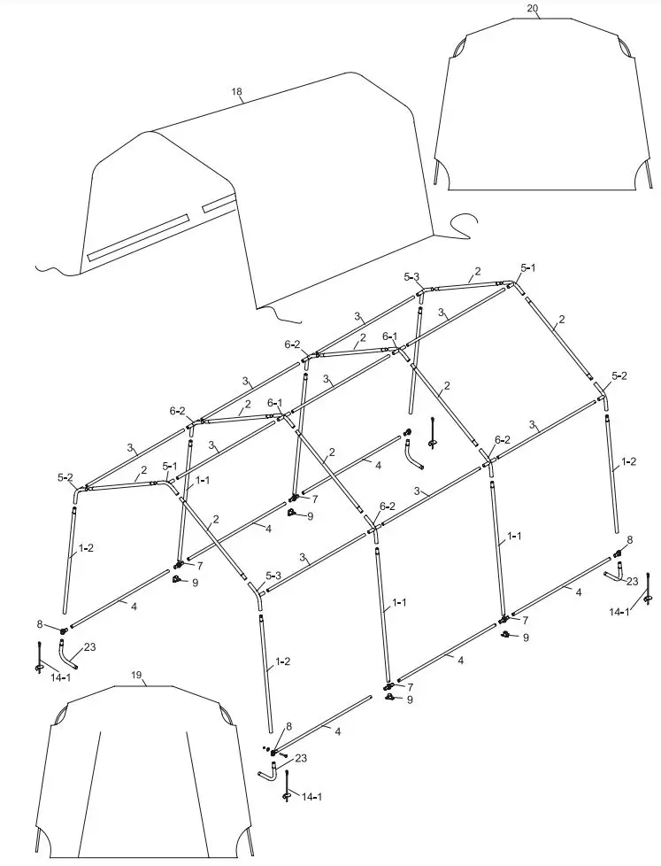
Frame Assembly Overview
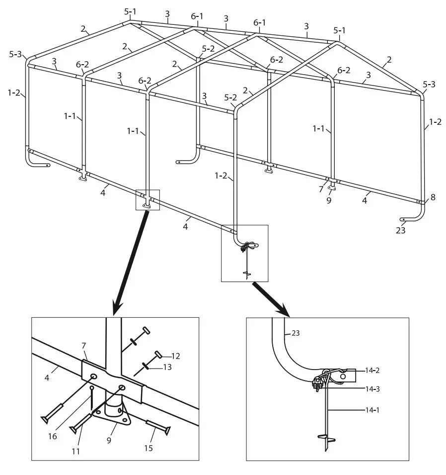
Roof Frame Assembly
Much of this product’s assembly is done using slip fit construction. Make sure all parts seat completely and securely. A rubber mallet (sold separately) can be used to gently tap parts in place to ensure a tight fit.
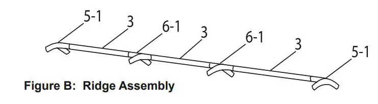
- Assemble ridge using three Rails (3) with 4-Way Ridge Connectors (6-1) between them, and a 3-Way Ridge Connector (5-1) on each end. The Rails connect to the straight ends of the Connectors and the curved, free ends of the Connectors are angled down, as shown.
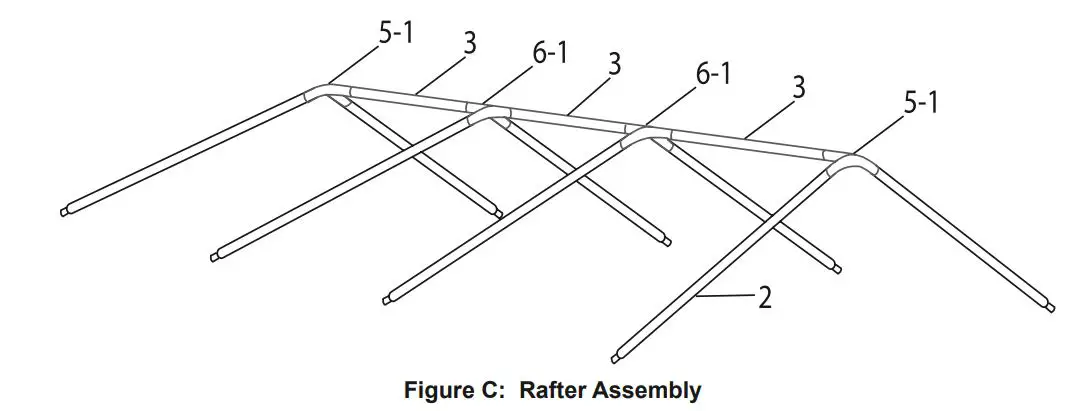
- Connect a Rafter (2) to each free end of every Connector (6-1, 5-1), as shown.
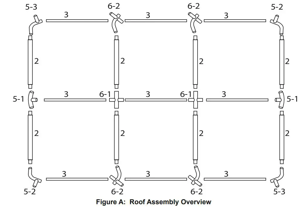
- Assemble a roof side rail using a 3-Way Side Connector B (5-3), then three Rails (3) with 4-Way Side Connectors (6-2) between them, and then a 3-Way Side Connector A (5-2) on the far end. The Rails connect to the straight ends of the Connectors, and the curved ends of all Connectors must face up angled the same direction, as shown. If that is not the case, incorrect connectors were used, or they were assembled backwards.
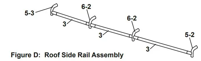
- Assemble a second identical roof side rail by repeating the instructions in step #3.
- Connect the roof side rail assemblies to the ends of the Rafters (2), as shown below.
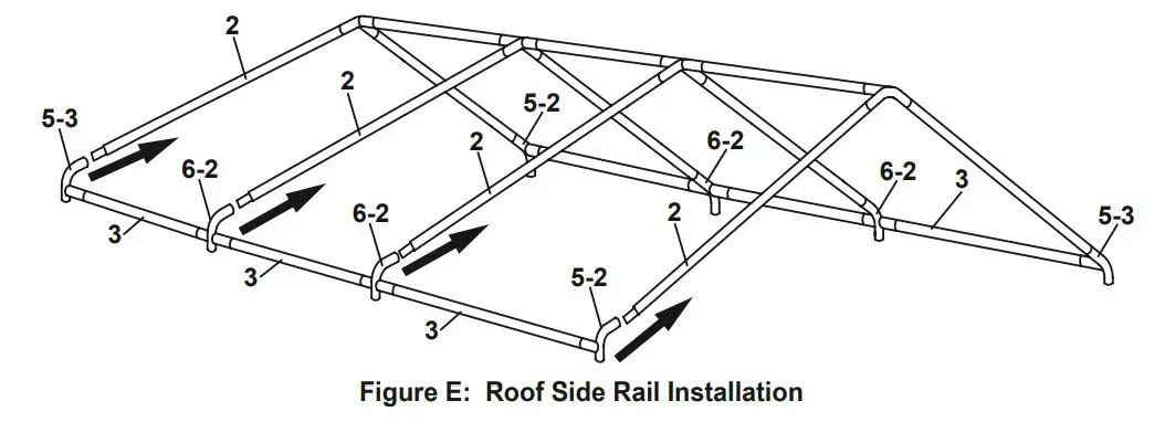
- Make sure all parts assembled up to this point are firmly joined together. Tap parts together gently with a rubber mallet (sold separately) if needed.
Stud, Foot, and Leg Assembly
- Assemble a Foot (9) to the bottom of each Center Stud (1-1):
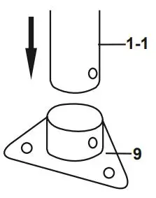
a. Place a Foot (9) onto the bottom of the Center Stud (1-1).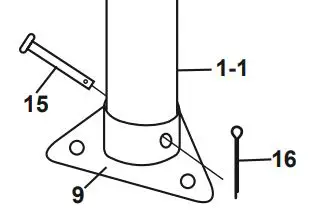
b. Align the holes and insert a Pin (15) through them.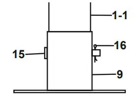
c. Insert a Cotter Pin (16) through the Pin, and spread end open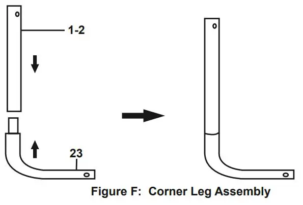
- Assemble a Corner Leg (23) to the bottom of each Corner Stud (1-2) as shown in Figure F.
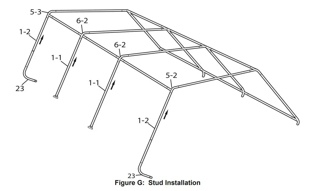
Stud Installation - Have assistants raise one side of the roof assembly.
- Install the Center Studs (1-1) into the 4-Way Side Connectors (6-2), and the Corner Studs (1-2) into the 3-Way Side Connector A/B (5-2, 5-3) with the Corner Legs (23) facing inward.
- After all four Studs (1-1, 1-2) are in place, rest that side of the assembly on the ground, and raise the other side.
- Install four Studs (1-1, 1-2) on the other side of the roof, as explained in step #2, above.
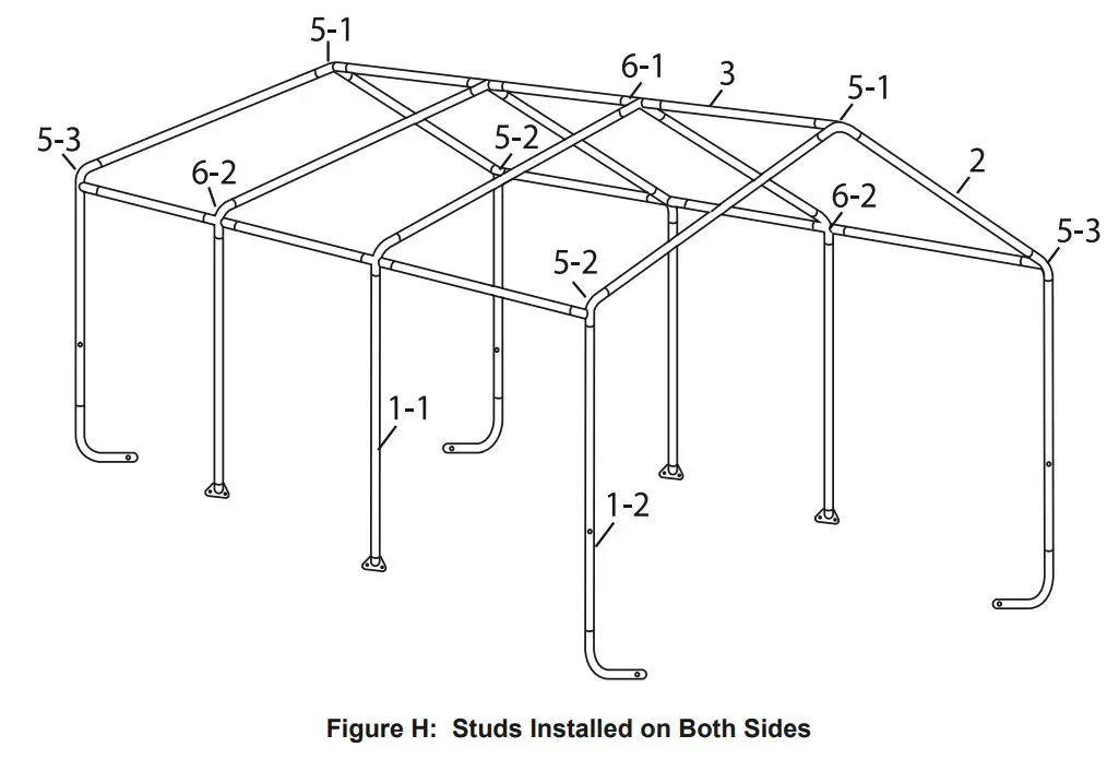
- Make sure all parts assembled up to this point are firmly joined together. Tap parts together gently with a rubber mallet (sold separately) if needed.
Anchoring Frame
![]() WARNING
WARNING
TO PREVENT SERIOUS INJURY: Contact local utility companies to ensure that the installation area is free of pipes, cables, and other hazards BEFORE installing anchors or choosing installation area.
- Position the frame in the desired installation location.
The location must be flat, level, and stable with good locations for the Anchors (14-1). - Level the frame end-to-end and side-to-side.
- Measure the width of the frame at front and back, it should be 10 2 wide. The distance diagonally in one direction should be equal to the distance diagonally in the other direction. If any measurements do not match, adjust the frame and retake measurements until they are equal within a reasonable tolerance.
Note: If measurements cannot be made correct, then parts may not be seated together properly.
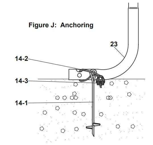
- Once the frame is positioned, levelled, and squared, anchor the four Corner Legs (23) as follows:
- a. Thread the Anchor (14-1) into the ground near the Corner Leg (23) until the top of the Anchor only extends about 3 above the ground.
Note: Verify that there are no utility lines nearby before driving anchors. If there are rocks or other obstacles, holes may need to be drilled first to allow proper anchoring. - b. Insert a Cable (14-2) through the anchor and through the Corner Leg (23), as shown.
- c. Pull the Cable (14-2) tight and secure it using a Cable Clamp (14-3). Tighten the two nuts on the Cable Clamp (14-3) evenly to secure the Cable (14-2).
- d. Repeat for all four Anchors (14-1) and Corner Legs (23).
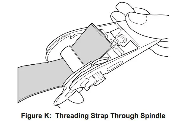
Securing Ratchet Tie-downs
Note: Use these instructions when installing Door, Back, and Roof cover.
- Thread the strap through the spindle of the Ratchet (22) as far as it will go.
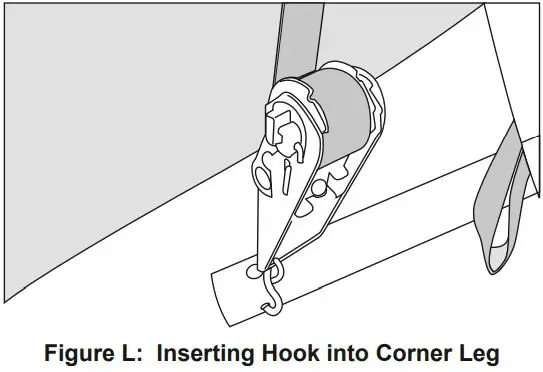
- Insert the S-hook of the Ratchet into the hole in the Corner Leg (23).
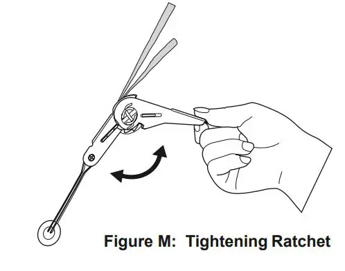
- Lift and lower the Ratchet’s handle to wind and tighten the strap onto the spindle.
Excessive tightening will damage straps, Covers, and Corner Legs.
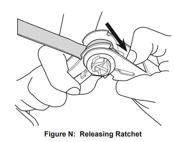
Releasing Ratchet Tie-downs
- Depress the spring-loaded bar on the handle.
- Open ratchet handle completely.
- Unwind the strap.
Door and Back Cover Installation
Note: When installing Door and Back cover, ensure that pre-installed straps are not pulled out of the Hem.
- Position the Door Cover (19) near where you want the front of the Portable Garage, and turn it so that the zipper faces the outside of the Portable Garage, and the warning tag faces inside.
- From the inside, disconnect the Rail (3) from the 3-Way Ridge Connector (5-1), and place the gap at the top center of the Door Cover around the Ridge Connector, as shown. Note that the Door Cover’s flaps wrap around the Rafters (2), and the strap is positioned inside the frame. DO NOT ATTEMPT TO INSERT ANY FRAMEWORK TUBING INTO THE HEM ON THE COVER FLAPS.
- Reconnect the Rail (3) securely to the 3-Way Ridge Connector (5-1).
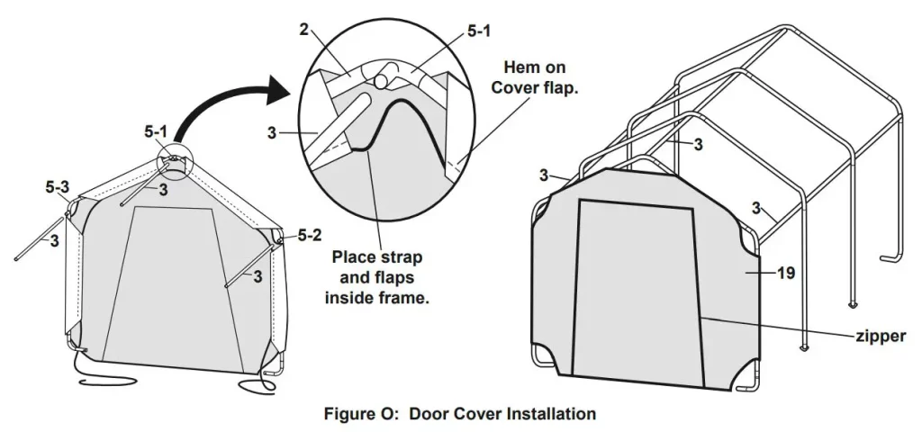
- Repeat step #2 for the 3-Way Side Connectors A/B (5-2, 5-3) so that the Door Cover (19) looks as shown in the illustrations above.
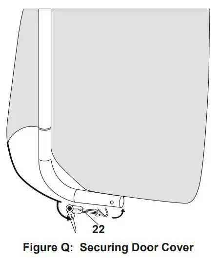
- Use Ratchet Tie-downs (22) to attach the Cover to the Corner Legs (23). Refer to Securing Ratchet Tie-downs on page 10 and Figure Q above.
- Repeat steps #1 4 above to install the Back Cover (20) to the other end of the Portable Garage.
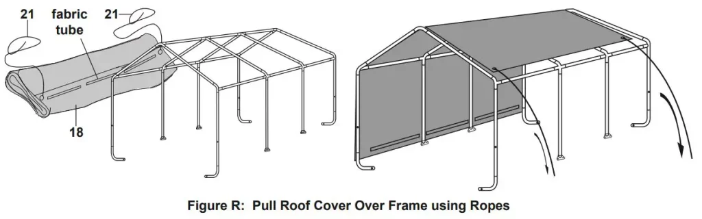
Roof Cover Installation
Note: Door and Back Covers (19, 20) not shown on illustrations to provide a clear view of installation.
- Lay the Roof Cover (18) on the ground next to the frame. Make sure that the edges with black straps are alongside the Door/Back Covers (19,20) and one set of the fabric tubes is facing upwards, see Figure R.
- Tie each Rope (21) through an eyelet at the corner of the Roof Cover.
- Throw the other ends of the Ropes (21) over the frame.
- Move to the other side of the frame and pull the Cover over the frame. Make sure that the Roof Cover is centred on the frame. If small adjustment is needed, two people should pull together from the same end of the Portable Garage so that the Roof Cover does not become twisted.
- Insert the Bottom Rails (4) into the fabric tubes on each side of the Roof Cover. Make sure the Bottom Rails are level and horizontal.
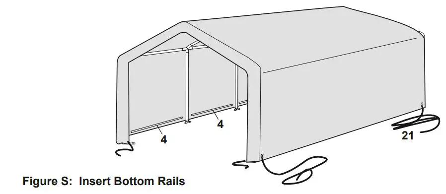
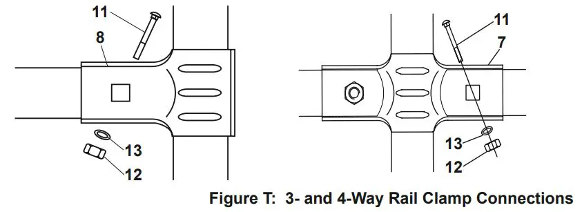
- Attach the Bottom Rails (4) to the Corner Studs (1-2) using 3-Way Rail Clamps (8), Bolts, Nuts and Washers (11, 12, 13), and to the Center Studs (1-1) with 4-Way Rail Clamps (7), as shown in Figure T.
- Make sure that all the bottom cross rails are of the same height from the ground, then tighten all Nuts (12).
- Secure the four corners to the Corner Legs (23) using Ratchet Tie-downs (22); see Securing Ratchet Tie-downs on page 10.
Maintenance
![]() Procedures not specifically explained in this manual must be performed only by a qualified technician.
Procedures not specifically explained in this manual must be performed only by a qualified technician.
![]() WARNING
WARNING
TO PREVENT SERIOUS INJURY FROM PRODUCT FAILURE: Do not use damaged products. If damage is noted, have the problem corrected before further use.
Inspection
MONTHLY, inspect the general condition of the Portable Garage. Check for:
- loose ratchet tie downs, anchors, tube connections, and rail clamps (tighten as needed),
- torn or frayed covers, ropes, or cables,
- cracked, bent, or broken parts, and
- any other condition that may affect its safe operation.
Cleaning
- Immediately remove any accumulated debris from the cover with a broom, mop, or other soft-sided instrument from the outside. DO NOT use sharp instruments.
- PERIODICALLY, clean cover with mild soap and water. DO NOT use bleach or harsh abrasive products.
PLEASE READ THE FOLLOWING CAREFULLY
THE MANUFACTURER AND/OR DISTRIBUTOR HAS PROVIDED THE PARTS LIST AND ASSEMBLY DIAGRAM IN THIS MANUAL AS A REFERENCE TOOL ONLY. NEITHER THE MANUFACTURER OR DISTRIBUTOR MAKES ANY REPRESENTATION OR WARRANTY OF ANY KIND TO THE BUYER THAT HE OR SHE IS QUALIFIED TO MAKE ANY REPAIRS TO THE PRODUCT, OR THAT HE OR SHE IS QUALIFIED TO REPLACE ANY PARTS OF THE PRODUCT. IN FACT, THE MANUFACTURER AND/OR DISTRIBUTOR EXPRESSLY STATES THAT ALL REPAIRS AND PARTS REPLACEMENTS SHOULD BE UNDERTAKEN BY CERTIFIED AND LICENSED TECHNICIANS, AND NOT BY THE BUYER. THE BUYER ASSUMES ALL RISK AND LIABILITY ARISING OUT OF HIS OR HER REPAIRS TO THE ORIGINAL PRODUCT OR REPLACEMENT PARTS THERETO, OR ARISING OUT OF HIS OR HER INSTALLATION OF REPLACEMENT PARTS THERETO.
Record Product’s Serial Number Here:_________________
If product has no serial number, record month and year of purchase instead.
Some parts are listed and shown for illustration purposes only, and are not available individually as replacement parts.
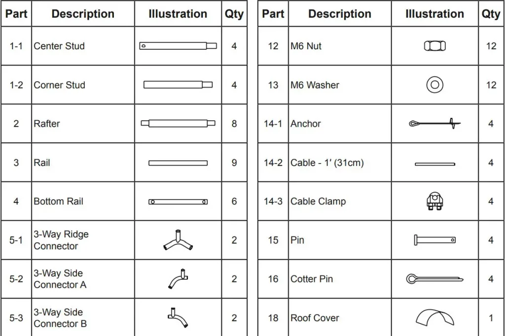
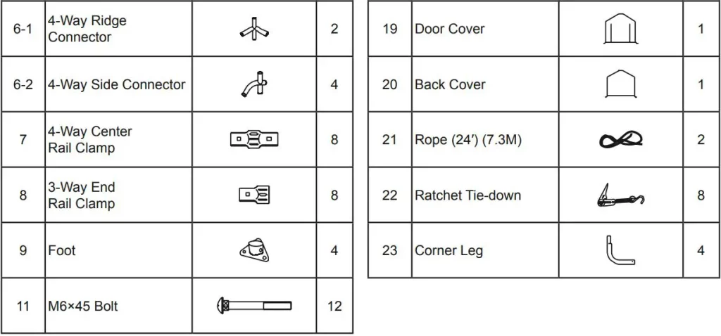
Parts List and Diagram
Parts List
Assembly Diagram
Limited 90 Day Warranty
Harbor Freight Tools Co. makes every effort to assure that its products meet high quality and durability standards, and warrants to the original purchaser that this product is free from defects in materials and workmanship for the period of 90 days from the date of purchase. This warranty does not apply to damage due directly or indirectly, to misuse, abuse, negligence or accidents, repairs or alterations outside our facilities, criminal activity, improper installation, normal wear and tear, or to lack of maintenance. We shall in no event be liable for death, injuries to persons or property, or for incidental, contingent, special or consequential damages arising from the use of our product. Some states do not allow the exclusion or limitation of incidental or consequential damages, so the above limitation of exclusion may not apply to you. THIS WARRANTY IS EXPRESSLY IN LIEU OF ALL OTHER WARRANTIES, EXPRESS OR IMPLIED, INCLUDING THE WARRANTIES OF MERCHANTABILITY AND FITNESS.
To take advantage of this warranty, the product or part must be returned to us with transportation charges prepaid. Proof of purchase date and an explanation of the complaint must accompany the merchandise. If our inspection verifies the defect, we will either repair or replace the product at our election or we may elect to refund the purchase price if we cannot readily and quickly provide you with a replacement. We will return repaired products at our expense, but if we determine there is no defect, or that the defect resulted from causes not within the scope of our warranty, then you must bear the cost of returning the product. This warranty gives you specific legal rights and you may also have other rights which vary from state to state.
26541 Agoura Road · Calabasas, CA 91302 · 1-888-866-5797
]]>Harbor Freight DAYTONA 3 Ton Super Duty Floor Jack DJ3000

IMPORTANT SAFETY INFORMATION
- Study, understand, and follow all instructions before operating this device.
- Do not exceed rated capacity.
- Use only on hard, level surfaces.
- Lifting device only. Immediately after lifting, support the vehicle with appropriate means.
- Do not move or dolly the vehicle while on the jack.
- Failure to heed these markings may result in personal injury and/or property damage.
- Lift only areas of the vehicle as specified by the vehicle manufacturer.
- No alterations shall be made to this product.
- Never work on, under or around a load supported only by this device.
- Do not adjust safety valve.
- Wear ANSI-approved safety goggles and heavy-duty work gloves during use.
- Keep clear of load while lifting and lowering.
- Lower load slowly
- Apply parking brake and chock tires before lifting vehicle.
- Lift vehicle only at manufacturer recommended locations.
- Inspect before every use; do not use if parts are loose or damaged, or if leaking hydraulic fluid
- Do not use for aircraft purposes.
- Do not use any objects (such as blocks of wood) in between Saddle Pad or Saddle and lifting point. Objects placed on the Saddle will reduce the stability of the Jack, and could allow the vehicle to slip off the Saddle and fall.
- The warnings, precautions, and instructions discussed in this manual cannot cover all possible conditions and situations that may occur. The operator must understand that common sense and caution are factors, which cannot be built into this product, but must be supplied by the operator
- The Handle socket may be held down by a clip under tension. Wear ANSI-approved safety goggles before freeing Handle socket. Remove clip carefully
- People with pacemakers should consult their physician(s) before use. Electromagnetic fields in close proximity to heart pacemaker could cause pacemaker interference or pacemaker failure.
 SAVE THESE INSTRUCTIONS.
IMPORTANT! Before first use:
Check hydraulic oil level and fill to 1/4″ below the Fill Plug hole as needed as stated on page 6. Thoroughly test the Jack for proper operation. If it does not work properly, bleed air from its hydraulic system as stated on page 6.
Specifications
| Weight Capacity | 3 Tons |
| Weight Capacity (lb.) | 6,000 |
| Maximum Height (in.) | 23.125 |
| Minimum Height (in.) | 3.75 |
| Handle Length (in.) | 50.25 |
| Front Wheel Diameter (in.) | 3.5 |
| Front Wheel Width (in.) | 2.0 |
| Rear Caster Diameter (in.) | 2.5 |
| Rear Caster Width (in.) | 1.375 |
| Saddle Pad Size (in.) | 5 x 5 sq. |
| Hydraulic Oil | non-detergent 22 weight |
| Weight (lb.) | 104 |
| Meets 2019 ANSI/ASME PASE standards | |
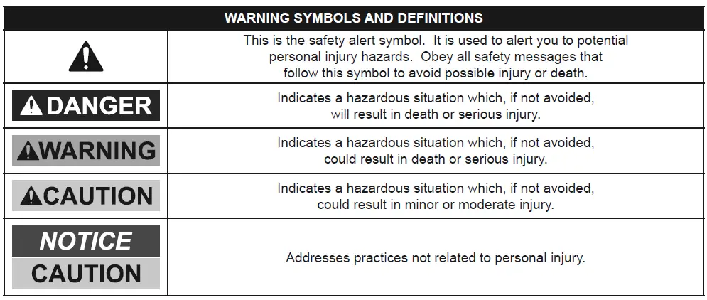
WARNING SYMBOLS AND DEFINITIONS |
|
|
This is the safety alert symbol. It is used to alert you to potential personal injury hazards. Obey all safety messages that follow this symbol to avoid possible injury or death. |
 |
Indicates a hazardous situation which, if not avoided, will result in death or serious injury |
 |
Indicates a hazardous situation which, if not avoided, could result in death or serious injury. |
 |
Indicates a hazardous situation which, if not avoided, could result in death or serious injury. |
 |
Addresses practices not related to personal injury. |
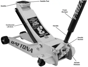
Features and Benefits
The Daytona [DJ3000] 3 Ton Professional Super Duty Jack was engineered for automotive professionals. The Model [DJ3000] features Advanced Rapid Pump® technology for fast lift times and exceptionally long life.
Long-Life Advanced Rapid Pump® Hydraulics
The hydraulic power unit is designed to provide over 5000 lift cycles with minimal wear.
An Integrated Magnetic Filtration (IMF) System prevents contaminants from damaging pump pistons and other high pressure components. Precision-engineered high performance seals along with a sealed non-vented reservoir ensure longer fluid life with no leaks.
Rapid Pump technology delivers twice the lift force with each stroke to lift heavy loads in half the time of conventional hydraulic systems. The pistons are continuously force-loaded to keep the pump handle in ready position during use. Load limiters with a bypass valve protect the pump if an overweight load is attempted.
Low-Profile/High Lift Saddle
The Low Profile design gives you a minimum height of just 3.75 for working with low-clearance vehicles. The extended lift arm provides High Lift for a maximum height of 23.125 for plenty of working space when properly supported. The big 5 x 5 saddle supports lift points solidly without danger of slipping. The saddle can be removed to install lifting accessories (sold separately.)
Super Duty Strength and Durability
The Daytona Super Duty Professional Jack chassis is constructed from all-welded steel plate with I-beam reinforcement for extraordinary strength and reliability. Contoured steel wheels and casters roll smoothly with less surface area contact for exceptional mobility. Fully lubricated with dual bearings and easy access grease fittings.
Effortless Operation
Get easy leverage and positioning with the extra long foam-protected lift handle. All moving components are factory lubed for smooth action with easily serviceable grease fittings in the lift mechanism. A locking spring mechanism keeps the handle in place during use.
The Rapid Pump® system gives you easy-twist universal joint hydraulic release for precise, controlled lowering.
Feature Summary:
- Integrated Magnetic Filtration (IMF) System extends pump life by eliminating contaminants
- Rapid Pump® technology to reach working height with the fewest strokes
- Low Profile with a lowered height of 3.75 for low clearance vehicles
- High Lift for a maximum height of 23.125
- Super Duty all-welded steel I-beam construction
- Contoured lift arm for ample rocker panel side clearance
- Pumps and ram pistons with long-life precision milled premium seals
- Big 5 x 5 saddle with rubber cushioned pad and option for accessories
- Easy access grease fittings in lift arm pivot, handle socket and front wheels
- All-steel contoured wheels for easy mobility
- Knurled long-reach lift handle locks in place, foam guard to protect vehicle finish
- Powder coated finish for durability
Overview
Set Up
Read the IMPORTANT SAFETY INFORMATION section at the beginning of this manual including all text under subheadings therein before set up or use of this product.
Removing Shipping Clip
The Handle socket may be held down by a clip under tension. Wear ANSIapproved safety goggles before freeing Handle socket. Remove clip carefully.
A wire clip holds the Handle Socket in position during shipment. This helps prevents shipping damage. To remove it:
- Press down on the Handle Socket to relieve tension on the wire clip.
- Slowly raise the Handle Socket until tension is released
- Disconnect the wire clip legs from the bar
- Remove the wire clip.
Attaching the Handle
- Slide the Upper Handle into the Lower Handle. Line the Button on the Lower Handle up with the hole in the Upper Handle until it clicks into place
- Pull on the Handle Release and insert the grooved end of the Handle into the Handle Socket
- Let go of the Handle Release. Gently pull up on the Handle to make sure that it is secure.
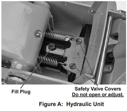
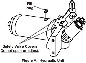
Bleeding Trapped Air
- With the Jack fully lowered, remove both Screws on the end of the Cover Plate that is closer to the Saddle. Swing the Cover Plate open. See Figure A.
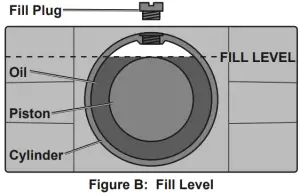
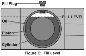
- Remove the Fill Plug on top of the Cylinder. Check that the oil level inside the Cylinder is at the top of the Piston. See Figure B.
- Insert the Handle into the Handle Socket to operate the Release Valve.
- Turn the Handle counterclockwise to open the valve.
- Pump the Handle up and down quickly 10-15 times to force air from the system.
- Replace the Fill Plug, close the Cover Plate, and reinstall the Screws.
Adding Oil
NOTICE: To prevent damage and premature wear, use only 22 viscosity, non-detergent hydraulic jack oil.
- With the Jack fully lowered, remove both Screws on the end of the Cover Plate that is closer to the Saddle. Swing the Cover Plate open.
- Remove the Fill Plug on top of the Cylinder.
- Add non-detergent 22 weight hydraulic jack oil into the Fill Plug hole slowly until the oil level just reaches the top of the Piston inside the Cylinder.
- Replace the Fill Plug, close the Cover Plate, and reinstall the Screws.
Operation
Read the ENTIRE IMPORTANT SAFETY INFORMATION section at the beginning of this manual including all text under subheadings therein before set up or use of this product.
Lifting
Park vehicle on a flat, level, solid, surface safely away from oncoming traffic. Turn off the vehicle’s engine. Place the vehicle’s transmission in “PARK” (if automatic) or in its lowest gear (if manual). Set the vehicle’s emergency brake. Then, chock the wheels that are not being lifted.
- Turn the Handle counterclockwise to lower the Jack. Once the Jack is fully lowered, turn the Handle firmly clockwise to close it.
- Carefully position the Saddle of the Jack under the vehicle manufacturer’s recommended lifting point. (See vehicle manufacturer’s owner’s manual for location of frame lifting point.)
- Pump the Handle until the top of the Jack’s Saddle has nearly reached the vehicle lifting point. Position the Saddle directly under the vehicle’s lifting point.
- To lift the vehicle, pump the Handle of the Jack. Use smooth, full strokes.
- Once the vehicle is raised, slide a jack stand of appropriate capacity (not included) under a proper lifting point referred to in the vehicle owner’s manual. Always use two jack stands, position them at the same point on each side of the vehicle.
WARNING! The rated capacity of jack stands is per pair, not the individual capacities combined unless specifically noted on the product by the jack stand manufacturer. Do not exceed rated jack stand capacity. Ensure that the vehicle support points are fully seated in the saddle of both jack stands. Use a matched pair of jack stands per vehicle to support one end only. Failure to do so may result in the load suddenly falling, which may cause personal serious injury and/or property damage. - Center the vehicle’s lifting point(s) on the saddle of the jack stand(s). Set the jack stand(s) to the same height according to the manufacturer’s instructions, making sure that they lock securely into position.
- Slowly turn the Handle counterclockwise to lower the vehicle onto the saddle(s) of the jack stand(s). Then, turn the Handle firmly clockwise to close it.
Lowering
- Carefully remove all tools, parts, etc. from under the vehicle.
- Position the Saddle under the lifting point. Turn the Handle firmly clockwise and raise load high enough to clear the jack stands, then carefully remove jack stands
- Slowly turn the Handle counterclockwise (never more than 1/2 full turn) to lower the vehicle onto the ground.
- Lower the Jack completely. Then, store in a safe, dry location out of reach of children.
- To prevent accidents, turn off the tool and disconnect its power supply after use. Clean, then store the tool indoors out of children’s reach.
Maintenance and Servicing
Procedures not specifically explained in this manual must be performed only by a qualified technician.
TO PREVENT SERIOUS INJURY FROM TOOL FAILURE: Do not use damaged equipment. If abnormal noise or vibration occurs, have the problem corrected before further use.
1. BEFORE EACH USE, inspect the general condition of the tool. Check for:
● leaking hydraulic fluid,
● loose hardware obr parts,
● misalignment or binding of moving parts,
● cracked, bent or broken parts, and
● any other condition that may affect its safe operation.
ALSO, BEFORE EACH USE, thoroughly test the Jack for proper operation prior to actual use. If the Jack’s motion seems spongy or the Saddle does not lift completely, follow Bleeding instructions on page 6.
2. AFTER USE, wipe dry with a clean cloth. Then, store the Jack in a safe, dry location out of reach of children and other non-authorized people.
NOTICE: Storing the Jack in a humid area or exposing it to corrosive vapor voids the warranty.
3. Weekly – Jack Lubrication:
a. Lubricate according to the below steps using only general purpose lithium grease.
b. Inject grease into each of the 5 grease fittings.
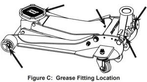
c. Lubricate the linkages and pivot points lightly.
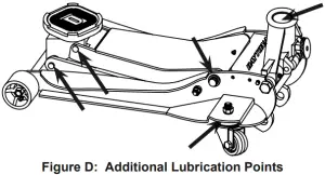
Note: Improper or inadequate lubrication voids the warranty.
4. Change the hydraulic oil at least once every three years:
a. With the Jack fully lowered, remove both Screws on the end of the Cover Plate that is closer to the Saddle. Swing the Cover Plate open.
b. Remove the Fill Plug on the top of the Cylinder.
c. Tip the Jack to allow the old hydraulic oil to drain out of the Housing completely, and dispose of the old hydraulic oil in accordance with local regulations.
d. Turn the Jack upright. Add non-detergent 22 weight hydraulic jack oil into the Fill Plug hole slowly until the oil level just reaches the top of the Piston inside the Cylinder.
e. Replace the Fill Plug, close the Cover Plate, and reinstall the Screws.
f. Follow instructions for Bleeding Trapped Air on page 6.
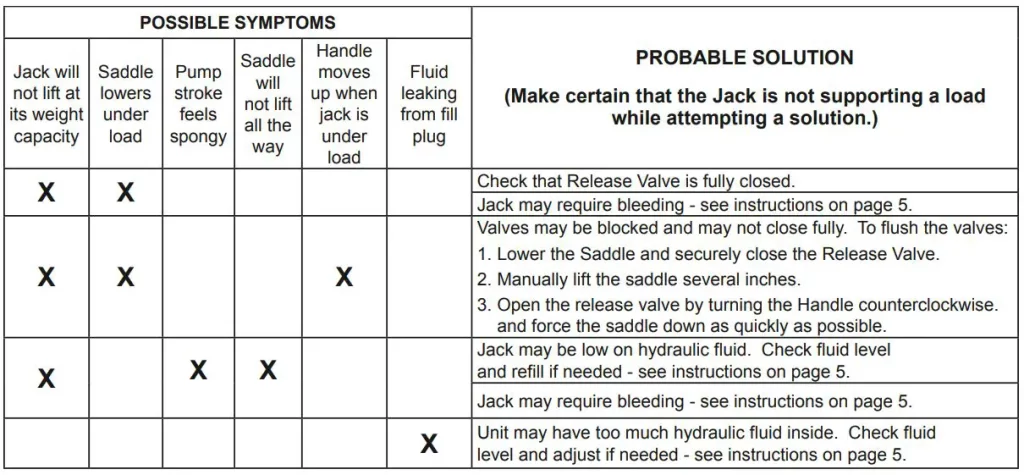
Troubleshooting
TO PREVENT SERIOUS INJURY: Use caution when troubleshooting a malfunctioning jack. Stay well clear of the supported load. Completely resolve all problems before use. If the solutions presented in the Troubleshooting guide do not solve the problem, have a qualified technician inspect and repair the jack before use. After the jack is repaired: Test it carefully without a load by raising and lowering it fully, checking for proper operation, BEFORE RETURNING THE JACK TO OPERATION.
DO NOT USE A DAMAGED OR MALFUNCTIONING JACK!
| POSSIBLE SYMPTOMS | PROBABLE SOLUTION
(Jack must not be supporting a load while attempting a solution.) |
||||
| Jack will not lift at capacity | Saddle lowers under load | Pump stroke feels spongy or Saddle does not lift all the way | Handle moves up when Jack under load | Fill Plug leaking oil or Jack will not lower without a load | |
| ✖ | ✖ | Check that Release Valve is fully closed. Bleed trapped air from the hydraulics. |
|||
| ✖ | ✖ | ✖ | Valves may be blocked and may not close fully. To flush the valves:
|
||
| ✖ | ✖ | Jack may be low on oil. Check the oil level and fill if needed. See step 4 on facing page. | |||
| Jack may have air trapped in the hydraulics. Follow instructions for Bleeding Trapped Air on page 6. | |||||
| ✖ | Jack may have too much hydraulic oil inside, check fluid level and adjust if needed.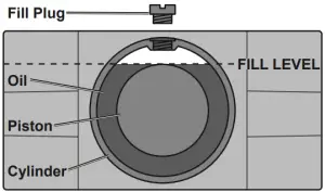 |
||||
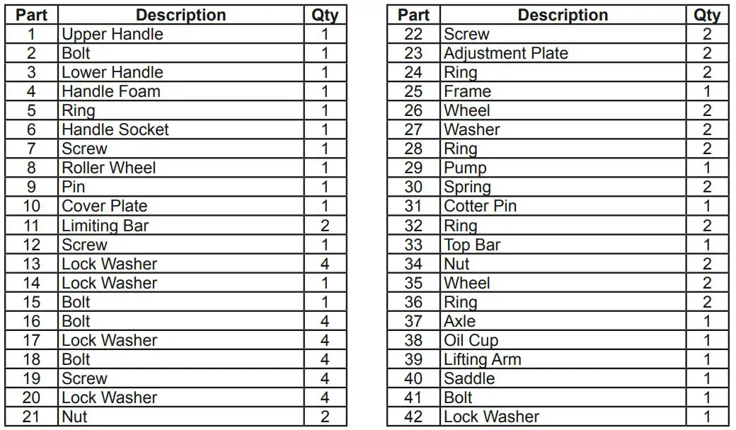
Parts List
| Part | Description | Qty. |
| 1 | Saddle Pad | 1 |
| 2 | Saddle Screw | 1 |
| 3 | Saddle | 1 |
| 4 | Lift Arm | 1 |
| 5 | Retaining Ring 16 | 2 |
| 6 | Front Wheel | 2 |
| 7 | Front Wheel Washer | 2 |
| 8 | Lock Nut M16 | 2 |
| 9 | Grease Fitting | 5 |
| 10 | Jack Frame | 1 |
| 11 | Support Bar Bolt | 2 |
| 12 | Retaining Ring 30 | 2 |
| 13 | Nut M16 | 4 |
| 14 | Screw M5X12 | 4 |
| 15 | Washer 16 | 4 |
| 16 | Washer 12 | 4 |
| 17 | Screw M12X22 | 4 |
| 18 | Rear Caster Assembly | 2 |
| 19 | Screw M8X20 | 4 |
| 20 | Washer 8 | 4 |
| 21 | Left Handle Socket Bolt | 1 |
| 22 | Washer 18 | 1 |
| 23 | Retaining Ring 25 | 2 |
| 24 | Return Spring | 2 |
| 25 | Hydraulic Pump Unit | 1 |
| 26 | Lower Handle | 1 |
| 27 | Foam Bumper | 1 |
| 28 | Handle Lock Clip | 1 |
| 29 | Upper Handle | 1 |
| 30 | U-Joint | 1 |
| 31 | Handle Release | 1 |
| 32 | Roller Pin | 1 |
| 33 | Roller | 1 |
| 34 | Retaining Ring 14 | 1 |
| 35 | Handle Socket | 1 |
| 36 | Split Pin 4X55 | 1 |
| 37 | Hydraulic Pump Block | 1 |
| 38 | Lower Tie Rod | 1 |
| 39 | Upper Tie Rod | 1 |
| 40 | Retaining Ring 18 | 1 |
| 41 | Right Handle Socket Bolt | 1 |
| 42 | Cover Plate | 1 |
| 43 | Support Bar | 2 |
| 44 | Fill Plug | 1 |
PLEASE READ THE FOLLOWING CAREFULLY
THE MANUFACTURER AND/OR DISTRIBUTOR HAS PROVIDED THE PARTS LIST AND ASSEMBLY DIAGRAM IN THIS MANUAL AS A REFERENCE TOOL ONLY. NEITHER THE MANUFACTURER OR DISTRIBUTOR MAKES ANY REPRESENTATION OR WARRANTY OF ANY KIND TO THE BUYER THAT HE OR SHE IS QUALIFIED TO MAKE ANY REPAIRS TO THE PRODUCT, OR THAT HE OR SHE IS QUALIFIED TO REPLACE ANY PARTS OF THE PRODUCT. IN FACT, THE MANUFACTURER AND/OR DISTRIBUTOR EXPRESSLY STATES THAT ALL REPAIRS AND PARTS REPLACEMENTS SHOULD BE UNDERTAKEN BY CERTIFIED AND LICENSED TECHNICIANS, AND NOT BY THE BUYER. THE BUYER ASSUMES ALL RISK AND LIABILITY ARISING OUT OF HIS OR HER REPAIRS TO THE ORIGINAL PRODUCT OR REPLACEMENT PARTS THERETO, OR ARISING OUT OF HIS OR HER INSTALLATION OF REPLACEMENT PARTS THERETO.
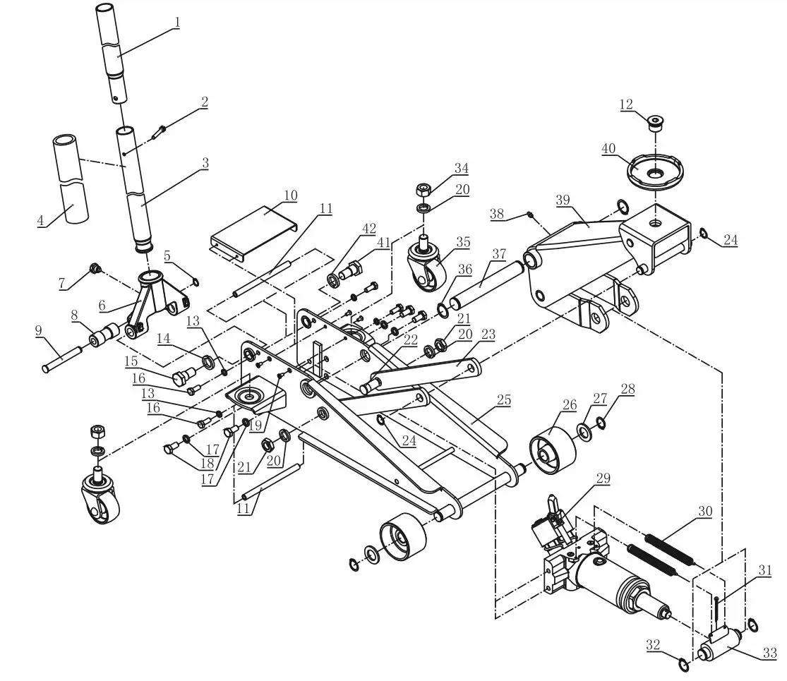
Assembly Diagram
Record Product’s Serial Number Here:
Note: If product has no serial number, record month and year of purchase instead.
Note: Some parts are listed and shown for illustration purposes only, and are not available individually as replacement parts. Specify UPC 57590 when ordering parts. Specify UPC 193175418524 when ordering parts.
Limited 3 Year Warranty
Harbor Freight Tools Co. makes every effort to assure that its products meet high quality and durability standards, and warrants to the original purchaser that this product is free from defects in materials and workmanship for the period of 3 years from the date of purchase. This warranty does not apply to damage due directly or indirectly, to misuse, abuse, negligence or accidents, repairs or alterations outside our facilities, criminal activity, improper installation, normal wear and tear, or to lack of maintenance. We shall in no event be liable for death, injuries to persons or property, or for incidental, contingent, special or consequential damages arising from the use of our product. Some states do not allow the exclusion or limitation of incidental or consequential damages, so the above limitation of exclusion may not apply to you. THIS WARRANTY IS EXPRESSLY IN LIEU OF ALL OTHER WARRANTIES, EXPRESS OR IMPLIED, INCLUDING THE WARRANTIES OF MERCHANTABILITY AND FITNESS. This warranty gives you specific legal rights and you may also have other rights which vary from state to state.
26541 Agoura Road · Calabasas, CA 91302 · 1-888-866-5797

HARBOR FREIGHT 60234 800 LB Low Lift Transmission Jack Owner’s Manual

Save This Manual Keep this manual for the safety warnings and precautions, assembly, operating, inspection, maintenance and cleaning procedures. Write the product’s serial number in the back of the manual near the assembly diagram (or month and year of purchase if product has no number).
Keep this manual and the receipt in a safe and dry place for future reference.
Specifications
| Weight Capacity | 800 lb. |
| Tilt | 55º forward, 8º back, 30º side |
| Maximum Height | 24-1/2″ |
| Minimum Height | 8-1/2″ |
WARNING SYMBOLS AND DEFINITIONS
 |
This is the safety alert symbol. It is used to alert you to potential personal injury hazards. Obey all safety messages that follow this symbol to avoid possible injury or death. |
| DANGER |
Indicates a hazardous situation which, if not avoided, will result in death or serious injury. |
| WARNING |
Indicates a hazardous situation which, if not avoided, could result in death or serious injury |
| CAUTION |
Indicates a hazardous situation which, if not avoided, could result in minor or moderate injury |
| NOTICE CAUTION |
Addresses practices not related to personal injury |
IMPORTANT SAFETY INFORMATION
WARNING
Read all safety warnings and instructions.
Save all warnings and instructions for future reference.
Failure to heed these markings may result in personal injury and/or property damage:
- Study, understand, and follow all instructions before operating this device.
- Do not exceed 800 lb. rated capacity.
- Use only on hard, level surfaces.
- Adequately support the vehicle before starting repairs.
- Use of this product is limited to the removal, installation, and transportation in the lowered position, of transmissions, transfer cases, and transaxles.
- Do not adjust safety valve.
- Wear ANSI-approved safety goggles and heavy-duty work gloves during use.
- Keep clear of load while lifting and lowering.
- Lower load slowly.
- Do not use for aircraft purposes.
- Inspect before every use; do not use if parts loose or damaged.
- Do not alter the jack or use attachments and/or adapters that are not supplied by the manufacturer.
- The warnings, precautions, and instructions discussed in this manual cannot cover all possible conditions and situations that may occur.
The operator must understand that common sense and caution are factors, which cannot be built into this product, but must be supplied by the operator.
SAVE THESE INSTRUCTIONS.
Setup
Read the ENTIRE IMPORTANT SAFETY INFORMATION section at the beginning of this manual including all text under subheadings therein before set up or use of this product.
WARNING: TO PREVENT SERIOUS INJURY:
Remove load from the jack before any procedure on this page.
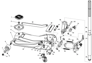
Note: For additional information regarding the parts listed in the following pages, refer to Parts List and Diagram.
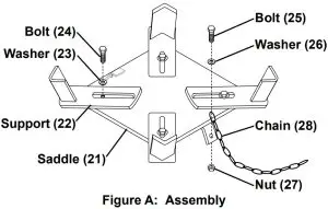
Assembly
- Connect a Support (22) to each corner of the Saddle (21) using a Bolt (24) and Washer (23).
- Use Bolt (25), Washer (26), and Nut (27) to attach the Chain (28) to the hole on the bracket on the Saddle, as shown.
Figure A: Assembly
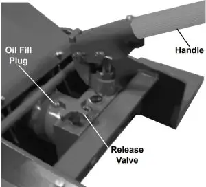
Checking/Filling Hydraulic Fluid
IMPORTANT! Before first use:
- Remove the Oil Fill Plug.
- Check hydraulic oil level and fill to 1/4″ below the fill port as needed.
- Replace the Oil Fill Plug.
- Thoroughly test the Jack for proper operation.
If it does not work properly, bleed air from its hydraulic system as described in Bleeding, below.
Figure B: Hydraulic Fluid Service Parts
Bleeding
- Follow the Checking/Filling Hydraulic Fluid instructions above.
- Turn the Release Valve counterclockwise to open it.
- Pump the Handle up and down quickly several times to purge air from the system.
- Check hydraulic oil level and fill to 1/4″ below the fill port as needed.
- Replace the Oil Fill Plug and close the Release Valve by turning it clockwise.
Functions
Operation
Read ENTIRE IMPORTANT SAFETY INFORMATION section at beginning of this manual including all text under subheadings therein before set up or use of this product.
Removing a Transmission
- Before every use, check and/or fill Hydraulic Fluid.
- Once the vehicle is raised and secured on a lift, clear the area underneath the vehicle of people and tools.
- Disconnect one end of the Chain and allow it to hang down.
- Move the Transmission Jack underneath the transmission.
- Close the Release Valve.
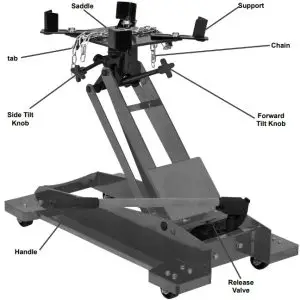
- Pump the Handle to raise the Transmission Jack.
- Stop just below the transmission and align the Saddle to the Transmission with the Tilt Knobs.
- Continue raising the Saddle up to the transmission to determine where you will need to adjust the Supports. All four Supports need to grip and make contact with the transmission.
- After determining where they need to be set, loosen the threaded bolts on each Support, and adjust it to the proper setting for the transmission. Tighten the bolts.
- Raise the unit again to make contact with the transmission, making sure all of the Supports are in firm contact.
- Wrap the Chain securely around the transmission, and hook the Chain to the bracket on the other side of the saddle.
- Once it is securely fastened, release the bolts holding the transmission in place.
- Make sure the area is clear of people and tools, and verify that the transmission is securely held in place. Then, slowly open the Release Valve to lower the Transmission Jack.
- Move the Transmission Jack from under the vehicle and perform your desired maintenance.
Replacing a Transmission
- Move the Transmission Jack so that the transmission is lined up properly with its connection points.
- Close the Release Valve.
- Pump the Handle to gradually raise the Transmission Jack, while guiding it into place.
- Secure the transmission into place using its hardware.
- Double-check to make sure the transmission is securely installed.
- Disconnect one end of the Chain and allow it to hang down.
- Clear the area near the Transmission Jack, and slowly open the Release Valve to lower the Jack.
- Move the Transmission Jack clear of the vehicle.
Maintenance and Servicing
Procedures not specifically explained in this manual must be performed only by a qualified technician.
WARNING: TO PREVENT SERIOUS INJURY FROM TOOL FAILURE:
Do not use damaged equipment. If abnormal noise or vibration occurs, have the problem corrected before further use.
- BEFORE EACH USE, inspect the general condition of the equipment. Check for:
- loose hardware,
- misalignment or binding of moving parts,
- visibly leaking hydraulic fluid,
- cracked or broken parts, and
- any other condition that may affect its safe operation.
- Before each use and after the inspection, thoroughly test the Jack for proper operation prior to its actual use. If the Jack appears not to be working properly, follow Bleeding instructions.
- Periodically, inject grease into the Zerk fitting on the main platform of the Transmission Jack.
- Change the hydraulic oil at least once every three years:
- With the Jack fully lowered, remove the Oil Filler Plug on the side of the Housing.
- Tip the Jack to allow the old hydraulic oil to drain out of the Housing completely, and dispose of the old hydraulic oil in accordance with local regulations.
- With the Jack upright, completely fill the Housing with a high quality hydraulic oil (not included) until the oil just begins to run out of the Oil Fill Hole.
- Open the Release Valve and pump the Handle to bleed air from the system.
- Reinstall the Oil Filler Plug.
- Wipe dry with a clean cloth.
Then, store the Jack in a safe, dry location out of reach of children and other non-authorized people.
Troubleshooting
WARNING
TO PREVENT SERIOUS INJURY: Use caution when troubleshooting malfunctioning jack. Stay clear of supported load. Completely resolve all problems before use.
If solutions presented in Troubleshooting guide do not solve the problem, have a qualified technician inspect and repair jack before use. After jack is repaired: Test it carefully without a load by raising and lowering it fully, checking for proper operation, BEFORE RETURNING JACK TO OPERATION.
DO NOT USE A DAMAGED OR MALFUNCTIONING JACK!
| POSSIBLE SYMPTOMS |
PROBABLE SOLUTION (Make certain that the Jack is not supporting a load while attempting a solution.) |
|||||
| Jack will not lift at its weight capacity | Saddle lowers under load | Pump stroke feels spongy | Saddle will not lift all the way | Handle moves up when Jack is under load | Oil leaking from Filler Plug | |
| X | X | Check that Release Valve is closed fully. Bleed air from the system. | ||||
| X | X | X | Valves may be blocked and may not close fully. To flush the valves:
|
|||
| X | X | X | Jack may be low on oil. Check the oil level and refill if needed. | |||
| Jack may require bleeding – see instructions on page 3. | ||||||
| X | Unit may have too much hydraulic oil inside, check fluid level and adjust if needed. | |||||
Parts List and Diagram
| Part | Description | Qty | Part | Description | Qty | Part | Description | Qty | ||
| 1 | Base | 1 | 15 | Bracket | 1 | 29 | Shaft | 1 | ||
| 2 | Lifting Arm | 1 | 16 | Shaft | 1 | 30 | Retaining Ring 22 | 2 | ||
| 3 | Long Connecting Bar | 2 | 17 | Retaining Ring 18 | 6 | 31 | Split Pin 4*50 | 1 | ||
| 4 | Short Connecting Bar | 2 | 18 | Shaft | 1 | 32 | Hydraulic Assembly | 1 | ||
| 5 | Bushing | 2 | 19 | Shaft | 1 | 33 | Release Valve | 1 | ||
| 6 | Square Shaft | 1 | 20 | Side Tilt Knob | 1 | 34 | Handle | 1 | ||
| 7 | Bearing | 3 | 21 | Saddle | 1 | 35 | Bolt M8x20 | 2 | ||
| 8 | Lock Nut M10 | 2 | 22 | Support | 4 | 36 | Spring Washer 8 | 2 | ||
| 9 | Shaft | 1 | 23 | Large Washer 10 | 4 | 37 | Bolt M6*14 | 16 | ||
| 10 | Spring Pin | 2 | 24 | Bolt M10x20 | 4 | 38 | Flat Washer 6 | 16 | ||
| 11 | Flat Washer 10 | 2 | 25 | Bolt M6x20 | 1 | 39 | 2″ Swivel Caster | 4 | ||
| 12 | Forward Tilt Knob | 1 | 26 | Flat Washer 6 | 1 | 40 | Spring Washer 6 | 16 | ||
| 13 | Shaft | 1 | 27 | Nut M6 | 1 | 41 | Nut M6 | 16 | ||
| 14 | Retaining Ring 16 | 8 | 28 | Chain | 1 | 42 | Zerk Fitting | 2 |
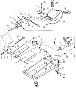
Record Product’s Serial Number Here:
Note: If product has no serial number, record month and year of purchase instead.
Note: Some parts are listed and shown for illustration purposes only, and are not available individually as replacement parts. Specify UPC 792363602341 when ordering parts.
PLEASE READ THE FOLLOWING CAREFULLY
THE MANUFACTURER AND/OR DISTRIBUTOR HAS PROVIDED THE PARTS LIST AND ASSEMBLY DIAGRAM IN THIS MANUAL AS A REFERENCE TOOL ONLY. NEITHER THE MANUFACTURER OR DISTRIBUTOR MAKES ANY REPRESENTATION OR WARRANTY OF ANY KIND TO THE BUYER THAT HE OR SHE IS QUALIFIED TO MAKE ANY REPAIRS TO THE PRODUCT, OR THAT HE OR SHE IS QUALIFIED TO REPLACE ANY PARTS OF THE PRODUCT. IN FACT, THE MANUFACTURER AND/OR DISTRIBUTOR EXPRESSLY STATES THAT ALL REPAIRS AND PARTS REPLACEMENTS SHOULD BE UNDERTAKEN BY CERTIFIED AND LICENSED TECHNICIANS, AND NOT BY THE BUYER. THE BUYER ASSUMES ALL RISK AND LIABILITY ARISING OUT OF HIS OR HER REPAIRS TO THE ORIGINAL PRODUCT OR REPLACEMENT PARTS THERETO, OR ARISING OUT OF HIS OR HER INSTALLATION OF REPLACEMENT PARTS THERETO.
Limited 90 Day Warranty
Harbor Freight Tools Co. makes every effort to assure that its products meet high quality and durability standards, and warrants to the original purchaser that this product is free from defects in materials and workmanship for the period of 90 days from the date of purchase. This warranty does not apply to damage due directly or indirectly, to misuse, abuse, negligence or accidents, repairs or alterations outside our facilities, criminal activity, improper installation, normal wear and tear, or to lack of maintenance. We shall in no event be liable for death, injuries to persons or property, or for incidental, contingent, special or consequential damages arising from the use of our product. Some states do not allow the exclusion or limitation of incidental or consequential damages, so the above limitation of exclusion may not apply to you. THIS WARRANTY IS EXPRESSLY IN LIEU OF ALL OTHER WARRANTIES, EXPRESS OR IMPLIED, INCLUDING THE WARRANTIES OF MERCHANTABILITY AND FITNESS.
To take advantage of this warranty, the product or part must be returned to us with transportation charges prepaid. Proof of purchase date and an explanation of the complaint must accompany the merchandise.
If our inspection verifies the defect, we will either repair or replace the product at our election or we may elect to refund the purchase price if we cannot readily and quickly provide you with a replacement. We will return repaired products at our expense, but if we determine there is no defect, or that the defect resulted from causes not within the scope of our warranty, then you must bear the cost of returning the product.
This warranty gives you specific legal rights and you may also have other rights which vary from state to state.
CONTACT US
Visit our website at: http://www.harborfreight.com
Email our technical support at: [email protected]
When unpacking, make sure that the product is intact and undamaged. If any parts are missing or broken, please call 1-888-866-5797 as soon as possible.
Copyright© 2021 by Harbor Freight Tools®. All rights reserved.
No portion of this manual or any artwork contained herein may be reproduced in any shape or form without the express written consent of Harbor Freight Tools.
Diagrams within this manual may not be drawn proportionally. Due to continuing improvements, actual product may differ slightly from the product described herein. Tools required for assembly and service may not be included.
Read this material before using this product. Failure to do so can result in serious injury.
SAVE THIS MANUAL
For technical questions, please call 1-888-866-5797.

Safety Instructions
Save This Manual Keep this manual for the safety warnings and precautions, assembly, operating, inspection, maintenance and cleaning procedures. Write the product’s serial number in the back of the manual near the assembly diagram (or month and year of purchase if product has no number). Keep this manual and the receipt in a safe and dry place for future reference.
When unpacking, make sure that the product is intact and undamaged. If any parts are missing or broken, please call 1-888-866-5797 as soon as possible.
 WARNING
Read this material before using this product. Failure to do so can result in serious injury. SAVE THIS MANUAL.
IMPORTANT SAFETY INFORMATION
WARNING
To prevent serious injury, FIRE, and EXPLOSION:
- Keep dry. Do not open, drop, short-circuit, incinerate, expose to temperatures higher than 140° F, or charge/use if damaged.
- Only use included charging adaptors. Other adaptors may damage tool or cause fire.
- Do not submerge Light.
- Do not operate in explosive atmospheres, such as in the presence of flammable liquids, gases, or dust.
- People with pacemakers should consult their physician(s) before use. Electromagnetic fields in close proximity to heart pacemaker could cause pacemaker interference or pacemaker failure.
- Not a toy. Keep out of reach of children.
Lithium Battery Safety Warnings
 LITHIUM BATTERIES STORE A LARGE AMOUNT OF ENERGY AND WILL VENT FIRE OR EXPLODE IF MISTREATED:
- Keep Flashlight dry.
- DO NOT DO ANY OF THE FOLLOWING TO THE BATTERY PACK:
- a. Open,
- b. Drop,
- c. Short-circuit,
- d. Puncture,
- e. Incinerate, or
- f. Expose to temperatures greater than 140°F.
- Charge Flashlight only according to these instructions.
Charging Instructions
Read the ENTIRE IMPORTANT SAFETY INFORMATION section at the beginning of this document including all text under subheadings therein before set up or use of this product.
- Twist the adjustable band near the top of the Flashlight to expose the USB port.
- Insert the provided USB cable into USB port. See below.

- Insert the other end of the cable into a powered USB port.
- The Charge Light Indicator will light up Red during charging. After approximately 3 hours the Charge Light Indicator turns Green, indicating the Flashlight is fully charged and ready for use. Unplug the USB cable.
- Li-Ion BATTERY MUST BE RECYCLED OR DISPOSED OF PROPERLY.
Do not short, incinerate or open battery.
NOTICE: Do not leave the Battery in a discharged state. Charge the Battery every 3 months if the Flashlight is not in use. This will keep the Battery from wearing down and add to its life. Do not charge the Flashlight at temperatures below 40° F.
Battery Replacement
- Unthread the base of the Flashlight.

- Remove the old battery, noting polarity.
- Insert a new 3.7V, 2200mAh Li-ion battery into the flashlight, positive end first.
Operation Instructions
Read the ENTIRE IMPORTANT SAFETY INFORMATION section at the beginning of this document including all text under subheadings therein before set up or use of this product.
NOTE: Before using Flashlight for the first time, fully charge the Battery.
- Press the Power button at the bottom of the light once to turn on maximum brightness mode.
- Press again to switch the light to economy mode.
- Press a third time to turn the light off.
- To turn on TURBO mode, press and hold Power button for three seconds.
- When finished using the Flashlight, store indoors away from children.
NOTICE: Do not open the housing, there are no user-serviceable parts inside.
Specifications
| Battery | Rechargeable Li-Ion |
| Battery Rating | 3.7V / 2200 mAh |
| Brightness | 1800 Lumens |
Limited 90 Day Warranty
Harbor Freight Tools Co. makes every effort to assure that its products meet high quality and durability standards, and warrants to the original purchaser that this product is free from defects in materials and workmanship for the period of 90 days from the date of purchase. This warranty does not apply to damage due directly or indirectly, to misuse, abuse, negligence or accidents, repairs or alterations outside our facilities, criminal activity, improper installation, normal wear and tear, or to lack of maintenance. We shall in no event be liable for death, injuries to persons or property, or for incidental, contingent, special or consequential damages arising from the use of our product. Some states do not allow the exclusion or limitation of incidental or consequential damages, so the above limitation of exclusion may not apply to you. THIS WARRANTY IS EXPRESSLY IN LIEU OF ALL OTHER WARRANTIES, EXPRESS OR IMPLIED, INCLUDING THE WARRANTIES OF MERCHANTABILITY AND FITNESS.
To take advantage of this warranty, the product or part must be returned to us with transportation charges prepaid. Proof of purchase date and an explanation of the complaint must accompany the merchandise. If our inspection verifies the defect, we will either repair or replace the product at our election or we may elect to refund the purchase price if we cannot readily and quickly provide you with a replacement. We will return repaired products at our expense, but if we determine there is no defect, or that the defect resulted from causes not within the scope of our warranty, then you must bear the cost of returning the product.
This warranty gives you specific legal rights and you may also have other rights which vary from state to state.
Record Product’s Serial Number Here:_______________
Note: If product has no serial number, record month and year of purchase instead.
Note: Replacement parts are not available for this item. Reference UPC 193175440051.
Visit our website at: http://www.harborfreight.com
Email our technical support at: [email protected]

Owner’s Manual & Safety Instructions
Save This Manual Keep this manual for the safety warnings and precautions, assembly, operating, inspection, maintenance, and cleaning procedures. Write the product’s serial number in the back of the manual near the assembly diagram (or month and year of purchase if the product has no number). Keep this manual and the receipt in a safe and dry place for future reference.
![]()
Greenhouse
8’5″ L x 6’3″ W x 6’5″ H

47712
Visit our website at: http://www.harborfreight.com
Email our technical support at: [email protected]
When unpacking, make sure that the product is intact and undamaged. If any parts are missing or broken, please call 1-888-866-5797 as soon as possible.
 Read this material before using this product. Failure to do so can result in serious injury. SAVE THIS MANUAL.
| WARNING SYMBOLS AND DEFINITIONS | |
| This is the safety alert symbol. It is used to alert you to potential personal injury hazards. Obey all safety messages that follow this symbol to avoid possible injury or death. | |
 |
Indicates a hazardous situation that, if not avoided, will result in death or serious injury. |
|
Indicates a hazardous situation that, if not avoided, could result in death or serious injury. |
 |
Indicates a hazardous situation that, if not avoided, could result in minor or moderate injury. |
 |
Addresses practices not related to personal injury. |
IMPORTANT SAFETY INFORMATION
The warnings, precautions, and instructions discussed in this manual cannot cover all possible conditions and situations that may occur. The operator must understand that common sense and caution are factors, which cannot be built into this product but must be supplied by the operator.
Assembly / Installation Precautions
- Assemble only according to these instructions. Improper assembly can create hazards.
- Wear ANSI-approved safety goggles and heavy-duty work gloves during assembly.
- This unit contains pieces with sharp edges. The machined edges of the aluminum parts and the ends of the panel clips may be sharp. Handle all parts carefully.
- Keep assembly area clean and well-lit.
- Keep bystanders out of the area during assembly.
- Do not assemble when tired or when under the influence of alcohol, drugs, or medication.
- Product capabilities apply to properly and completely assembled products only.
- Locate the Greenhouse on a flat, level, surface. A concrete foundation is recommended for a high-quality installation.
Use / Service Precautions
- This product is not a toy. Do not allow children to play in or climb on this product. Although this greenhouse does include some caps, there are still some exposed sharp edges. In addition, protective covers may fall off in time. Children must be supervised if allowed near the greenhouse.
- SNOW/DEBRIS ACCUMULATION HAZARD. The heavy weight of accumulated snow or other debris can cause parts of this greenhouse to buckle suddenly. Do not allow debris to accumulate on top of the greenhouse. If snowfall is expected, place additional supports (not provided) underneath the Crown (35). NEVER enter a greenhouse with accumulated debris on top.
- Use as intended only.
- Inspect periodically; replace damaged parts immediately and do not enter the greenhouse if parts are loose or damaged.
- For your safety, service and maintenance should be performed regularly by a qualified technician.
![]() SAVE THESE INSTRUCTIONS.
SAVE THESE INSTRUCTIONS.
Specifications
| Overall Dimensions | 98-1/2″ L x 75-7/8″ W x 77″ H |
| Window Dimensions | 23″ L x 20″ W |
| Door Dimensions | 64″ H x 24″ W x 1-1/4″ Thick |
| Materials | Aluminum Frame Transparent Polycarbonate Sheets |
| Aluminum Thickness | 0.038″ |
| Polycarbonate Sheet Thickness | 0.165″ |
Foundation Installation
![]() Read the ENTIRE IMPORTANT SAFETY INFORMATION section at the beginning of this document including all text under subheadings therein before set up or use of this product.
Read the ENTIRE IMPORTANT SAFETY INFORMATION section at the beginning of this document including all text under subheadings therein before set up or use of this product.
IMPORTANT–READ THE FOLLOWING CAREFULLY BEFORE PROCEEDING
- Prior to assembly, a proper foundation must be laid. The greenhouse must be properly supported to help prevent property damage and injury in the event of strong winds or inclement weather. Wind and ground conditions may vary from site to site and may affect the practicality and effectiveness of anchoring methods substantially. If you have any
doubt regarding the stability of the foundation you are to use, consult a professional. - It is always your responsibility to ensure that the greenhouse is properly anchored. Harbor Freight Tools cannot be held responsible for personal injury, damage to the greenhouse, or other property damage that occurs as a result of improperly anchoring the greenhouse.
- Be certain to check with local authorities to obtain all required building permits and to familiarize yourself with any building codes that may apply.
- Decide on a location for the greenhouse. The location should optimally be a level, well-lit area that is sheltered from the wind. The door of the greenhouse should not open towards the prevailing wind, if possible.
Concrete Anchor Foundation
- This foundation will be assembled out of 4 x 4 treated lumber, hardware, and prefabricated concrete anchors (none provided).
- Assemble the 4 x 4 pieces in the dimensions shown in the diagram below. The wood will need to be trimmed to fit. Make certain that the assembly is square and level.
The diagonal dimensions, from outside corner to outside corner, should be 123 3/4″ each. - Securely assemble the frame together using proper hardware.
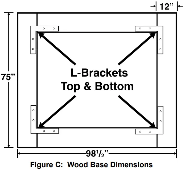
- Dig a hole for each of the concrete anchors in the positions shown. The hole should be slightly oversized and should be deep enough so that the frame will rest almost on the ground when installed.
- Carefully place the anchors in the holes, and place the frame on the anchors. Use a level on the frame to make sure that the anchors are sunk to the proper depth.
If any anchors need to be raised, partially fill the hole under the anchor with sand or gravel. - Once the frame is level, secure it to the anchors. Fill up the holes the rest of the way with the earth you removed previously.
- Optional: For convenience, you may fill the frame at this point with a proper fill material, such as gravel (not included).
- There are four Floor Plates to position on the foundation; the Front Floor Plate (17), the Rear Floor Plate (16), and two Side Floor Plates (34). (See Figure G on page 8.)
- Match the length of each of the four Floor Plates (16, 17, 34) with the appropriate length of each edge of the base. Place the Front Floor Plate (17) on the side that the door will face.
NOTE: Position the four Floor Plates (16, 17, 34) with their outer edges overhanging the outer edges of the frame, as shown below. Do not secure the Floor Plates to the Frame at this time.
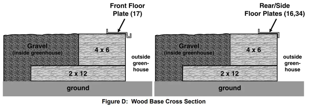
Treated Wood Base Foundation
- The wood base will be assembled out of 4 x 6 and 2 x 12 treated lumber, hardware (including galvanized lag bolts/deck screws), and fill material, such as gravel (none provided).
- Assemble the 2 x 12 pieces in the dimensions shown in the diagram below. The wood will need to be trimmed to fit. Make certain that the assembly is square and level. The diagonal dimensions, from outside corner to outside corner, should be 123 3 /4″ each. Also, use a level to ensure that the base is even. If needed, fill under sections of the base to make sure it is level.
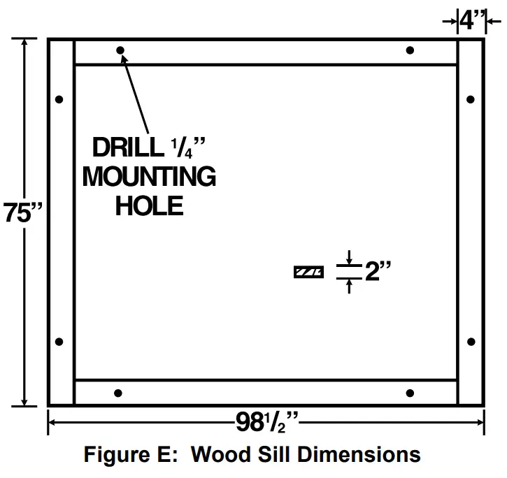
- Assemble the 4 x 6 pieces on top of the base you just assembled, as shown in the cross-section below. Fill the base with the fill material up to the top of the 4 x 6’s.
- There are four Floor Plates to position on the foundation; the Front Floor Plate (17), the Rear Floor Plate (16), and two Side Floor Plates (34). (See Figure G on page 8.)
- Match the length of each of the four Floor Plates (16, 17, 34) with the appropriate length of each edge of the base. Place the Front Floor Plate (17) on the side that the door will face.
NOTE: Position the four Floor Plates (16, 17, 34) with their outer edges overhanging the outer edges of the base, as shown below. Do not secure the Floor Plates to the Base at this time.
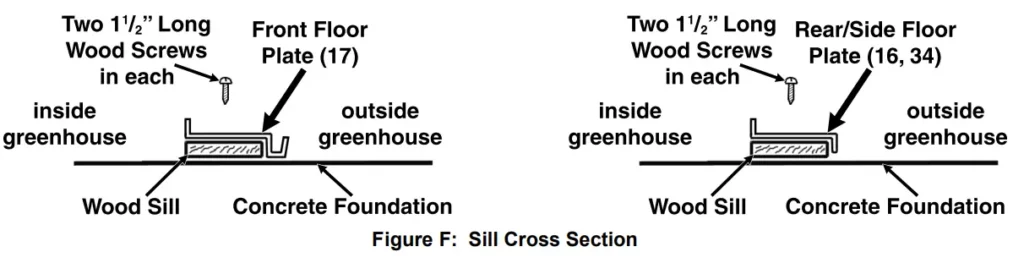
Concrete Slab Foundation
Constructing a Wooden Sill
- The greenhouse must be attached to a wood sill, and not directly to a concrete slab. Use four 4″ wide by 2″ thick wooden boards (not provided) to construct a sill.
- Cut the four boards to the proper dimensions shown.
- Place the four boards to form a rectangle on a level floor surface.
- Exact dimensions may vary slightly. Lay the base components out together, square them, then take actual measurements. Both diagonal measurements, from outer corner
to outer corner, should be 123 3/4″ each. - Secure the boards together at the corners using wood screws (not provided).

Attaching the Sill to the Concrete Slab
- A concrete slab foundation upon which The greenhouse will be positioned will help to ensure stability. The slab can be slightly oversize.
- Drill two ¼″ holes through each of the four boards.
- Next, use the two predrilled holes in each board as a template to mark the points where eight anchor holes will be drilled in the concrete floor. Then, temporarily remove the sill.
- Where previously marked on the concrete floor, drill all eight¼″ diameter, minimum ¼″ deep, anchor holes. Blow the concrete dust out from the drilled holes.
- Move the four boards back to the concrete floor surface, and align all eight predrilled holes in the four boards with the eight previously drilled anchor holes. If necessary, level the boards by inserting stainless steel shims (sold separately) between the boards and the concrete floor. Do not exceed ½″ shim thickness.
- Secure the four boards to the concrete floor, using eight ¼″ diameter anchor bolts of appropriate length, eight washers, and eight nuts (not provided).
Positioning the Floor Plates on the Sill
- There are four Floor Plates to attach to the sill; the Front Floor Plate (17), the Rear Floor Plate (16), and two Side Floor Plates (34). (See Figure G on page 8.)
- Match the length of each of the four Floor Plates (16, 17, 34) with the appropriate length of each of the four foundation boards. Place the Front Floor Plate (17) on the side that the door will face.
NOTE: Position the four Floor Plates (16, 17, 34) with their outer edges overhanging the outer edges of the sill, as shown below. Do not secure the Floor Plates to the Sill at this time.
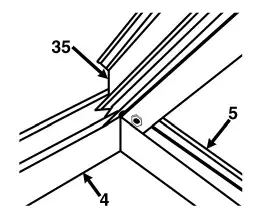
Frame Assembly
![]() Read the ENTIRE IMPORTANT SAFETY INFORMATION section at the beginning of this document including all text under subheadings therein before set up or use of this product.
Read the ENTIRE IMPORTANT SAFETY INFORMATION section at the beginning of this document including all text under subheadings therein before set up or use of this product.
- Unless noted otherwise, attach all frame parts using the Bolts (43) and Nuts (52) provided. Tighten nuts only about ¼ ” turn past finger tight; be careful not to overtighten.
- Layout all parts by number prior to assembly.
- Use an assistant or appropriate support (not included) to keep the partially assembled parts upright during assembly. Use two assistants to assemble the Crown pieces to the rest of the frame.
- Assemble on a clear, calm day. Wind will damage the Greenhouse and make assembly difficult.
Assembling the Frame Edges

- There are four Corner Studs (1) to be attached to the four Floor Plates (16, 17, 34). Attach one Corner Stud (1) on the outside of each corner. Attach an End Cap (47) to the top outer corner of each Corner Stud (1).
- Once the four Corner Studs (1) are connected to the Floor Plates (16, 17, 34), drill three pilot holes 1 ½″ through each Floor Plate and into the underlying wood sill or base. Make sure not to drill into any of the hardware used earlier. Then, secure the Floor Plates to the foundation, using three 1 ½″ long wood screws (sold separately) for each Floor Plate.
- Attach a Side Ceiling Plate (36) flat against the inside of two Corner Studs (1). Make sure that the gutter on the Side Ceiling Plate is oriented correctly, see Figure G inset. At this point, the completed section of the frame will likely need support.
- Attach the Rear Ceiling Plate (21) to the inside of the two Corner Studs (1) that are over the Rear Floor Plate (16). Point the Rear Ceiling Plate’s flange inward. (See Figure G.)
- Attach the Left and Right Rear Studs (8,9) to the outside of the Rear Floor Plate (16) and Rear Ceiling Plate (21). Orient them so that the ends slope upwards toward the middle of the greenhouse. (See Figure G.)
Note: The heads of the Bolts (43) fit into the slot on the back of the Stud, holding the Bolts in place during assembly.
- Attach the remaining Side Ceiling Plate (36) along the other side, flat against the inside of the Corner Studs (1), with the gutter oriented properly.
- At the side of the Greenhouse: Attach the Rear Right and Rear Left Crown Beams (4,5) to the outside of the Crown (35) with the angled edges towards the top. See diagram below, viewed from under the Crown, facing back.
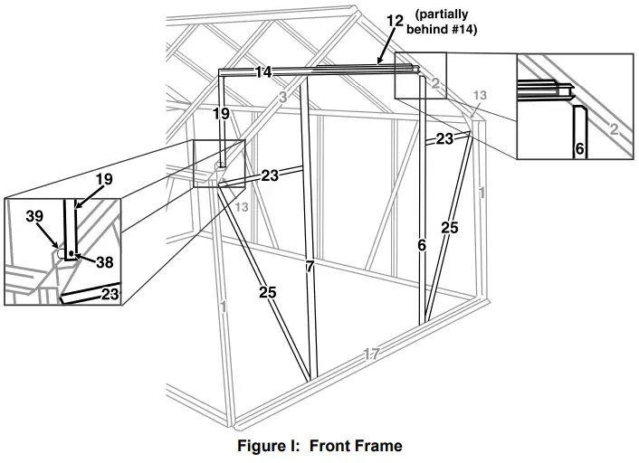
- Attach the Front Crown Beams (2,3) to the Crown (35) in the same fashion as the Rear Crown Beams.
- Attach an End Cap (47) onto the outer end of each Crown Beam (2-5). Cover the gaps between the Crown Beams (between 2-3 & 4-5) with a Peak Cap (54) in each.
- Attach a Corner Bracket (13) at the top of each Corner Stud (1) so that the bracket faces upwards, see diagram below. At the Studs that the Rear Ceiling Plate (21) is connected to, the Bolt (43) holding the Ceiling Plate will need to be removed temporarily while the Bracket is installed between the Rear Ceiling Plate and the Corner Stud.
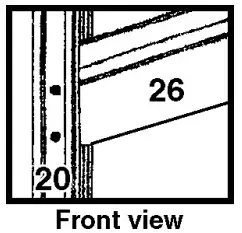
- With two assistants, lift the Crown Assembly and place the Crown Beams (2-5) on top of the Corner Brackets (13).
- Attach the remaining Side Ceiling Plate (36) flat against the inside of two Corner Studs (1). Once again, verify that the gutter on the Side Ceiling Plate is oriented correctly, see Figure C inset. At this point, the unit should be more stable.
- Place the Gutter Caps (48) onto the ends of the Side Ceiling Plates (36) oriented with a gap in the bottom to allow water to drain out of the gutters.
Assembling the Side and Roof Frames
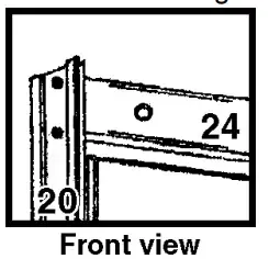
IMPORTANT: Assemble all parts marked with an asterisk (*) above with an extra Bolt (43) in the slot.
Figure H: Stud and Brace Locations
- Attach three Side Vertical Studs (10) to a Side Floor Plate (34) and a Side Ceiling Plate (36). Make sure that they are assembled vertically, there are extra holes for the diagonals. Also, include extra Bolts in the Studs noted above with asterisks. Repeat this step for the remaining Side Floor Plate and Side Ceiling Plate. (See Figure H.)
- Attach two Side Diagonal Braces (22) to a Side Floor Plate (34) and a Side Ceiling Plate (36) with the flange facing inward. Use the extra Bolt (43), noted in the caption above, to secure the center portion of each Diagonal Brace (22). Repeat this step for the remaining Side Floor Plate and Side Ceiling Plate. (See Figure H.)
- Attach the six Roof Studs (11) between the Crown (35) and the two Side Ceiling Plates (36). Include extra Bolts in the four Studs noted with an asterisk above. (See Figure H.)
- Slide the Window Support Beams (15) onto the four Roof Studs (11) that you included extra bolts in, with the predrilled holes on the underside and the flat side facing the Crown (35). Use the extra Bolts (43), to secure the Beam loosely in place. It will need adjustment when installing the window.
- Using two Window Screws (45), attach each Window Stop (18) to the Window Support Beam (15) with its tab pointing towards the Crown (35). Both should be on the underside of their Window Support Beam, inside the greenhouse.
Assembling the Front Frame
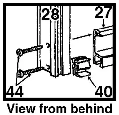
- Attach the Right and Left Doorway Studs (6,7) to the Front Right and Left Crown Beams (2,3) and the Front Floor Plate (17) as shown above. The cutoff corners on the Studs should be at the top and should face away from the center of the greenhouse. (See Figure I and right inset.)
- Attach the Front Diagonal Stud (25) to the lower Bolt on the Corner Bracket (13) and bottom of the Front Floor Plate (17). The flange should face inside. (See Figure I.)
- Attach the other Front Diagonal Stud (25) in the same way on the opposite side.
- Attach a Front Ceiling Plate (23) to the Bolt (43) on the Corner Bracket (13) that is right above the Diagonal-Bracket connection. Connect the other end to the Left Doorway Stud (7). Attach the remaining Front Ceiling Plate (23) between the Corner Bracket (13) and Right Doorway Stud (6). (See Figure I.)
- Attach the Top Doorway Beam (12) between the Front Right and Left Crown Beams (2,3). Turn it so that the nicked corners are facing up and the two remaining holes are facing the outside to allow the Door Rail (14) to be attached.
- Attach the Vertical Extender (19) to the Front Left Crown Beam (3) using the Long Door Support Bolt (38) and Nut (52), with the Door Support Spacer (39) between the Extender and the Stud. (See Figure I, left inset.)
- Place three Bolts (43) in the Slot at the back of the Door Rail (14). Attach the Rail to the Top Doorway Beam (12) and the free end of the Vertical Extender (19), with the rounded side up. (See Figure I.)
Assembling/Installing the Door
The door is assembled using the Door Screws (44). The Screws thread directly into the rounded portions of the parts in the center of the door.
- Place the Left Door Frame (20) with the Rubber Seal (42) side down. Attach the Center Door Frames (26) to the Left Door Frame (20). Assemble them with the rounded portion facing the front, as shown to the right. These parts are also marked with an arrow that needs to point towards the top of the door.
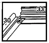
- Attach the Right Door Frame (28) to the Center Door Frames (26) in the same way.
- Attach the Door Top Frame (24) to the Left and Right Door Frames (20 and 28). Turn them so that the rounded portion faces the front and that the flange where the pane will sit faces the center of the door, see the diagram to the right.

- Using two Bolts (43) and two Nuts (52), attach the Door Slider (31) to the Door Top Frame (24) with the rollers on the top of the door.
- Insert a Door Bottom Slider (40) into each end of the Bottom Door Frame (27). Install the Sliders correctly, with the gap facing the back of the door, see diagram to the right. Attach the Bottom Door The frame (27) to the Left and Right Door Frames (20,28) using two Screws (44) on each side – the top one into the Bottom Door Frame (27) and the bottom one into the Door Bottom Slider (40).
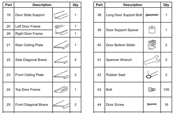
- Raise the assembled Door up and insert the first roller of its Door Slider (31) onto the Door Rail (14). Carefully align the first Bottom Door Slider (40) over the edge
of the Front Floor Plate (17), see illustration to the right. Carefully slide the door over and align the other top Roller and bottom Slider as was done earlier. - Once the door is installed, install a Bolt (43) and Nut (52) into the hole on each side of the Door Rail (14) to prevent the door from sliding off its rail. Attach the Right and Left Rail End Caps (49,50) onto the ends of the Door Rail.
Assembling/Installing the Windows
Follow the steps below for each of the two windows.
- Attach the Side Window Frames (30) to the Top Window Frame (33), as shown to the right.

- Insert Bolts (43) into the holes at the bottom of the Side Window Frames (30), so that the threads stick out the bottom of the window.
- Remove the protective film from both sides of the Window Pane (5A). Slide the Window Pane (5A) into the three-sided frame.
- Slide the Bottom Window Frame (32) onto the two bolts (43) and the Window Pane (5A). Secure it in place with Nuts (52). If needed, apply some pressure to the heads of the Bolts through the Window Pane to allow the Nuts to thread on properly.
- Attach the Window Brace (51) to the Bottom Window Frame (32) using two Window Screws (45). The holes on the Window Brace (51) should face away from the window.
- Slide the top edge of the Top Window Frame (33) into the slot at the top of the Crown (35), see illustration to the right. The window should
be aligned with the Window Brace (51) on the bottom. Slide the window into place over one Window Support Beam (15). Gradually lower it into place. - Loosen the nuts (52) holding the Window Support Beam (15) in place and slide the Window Support Beam (15) up to touch the window. Secure it into place.
Limited 90 Day Warranty
Harbor Freight Tools Co. makes every effort to assure that its products meet high quality and durability standards, and warrants to the original purchaser that this product is free from defects in materials and workmanship for the period of 90 days from the date of purchase. This warranty does not apply to damage due directly or indirectly, to misuse, abuse, negligence or accidents, repairs or alterations outside our facilities, criminal activity, improper installation, normal wear, and tear, or lack of maintenance. We shall in no event be liable for death, injuries to persons or property, or for incidental, contingent, special or consequential damages arising from the use of our product. Some states do not allow the exclusion or limitation of incidental or consequential damages, so the above limitation or exclusion may not apply to you. THIS WARRANTY IS EXPRESSLY IN LIEU OF ALL OTHER WARRANTIES, EXPRESS OR IMPLIED, INCLUDING THE WARRANTIES OF MERCHANTABILITY AND FITNESS.
To take advantage of this warranty, the product or part must be returned to us with transportation charges prepaid. Proof of purchase date and an explanation of the complaint must accompany the merchandise. If our inspection verifies the defect, we will either repair or replace the product at our election or we may elect to refund the purchase price if we cannot readily and quickly provide you with a replacement. We will return repaired products at our expense, but if we determine there is no defect, or that the defect resulted from causes not within the scope of our warranty, then you must bear the cost of returning the product. This warranty gives you specific legal rights and you may also have other rights which vary from state to state.
PLEASE READ THE FOLLOWING CAREFULLY
THE MANUFACTURER AND/OR DISTRIBUTOR HAS PROVIDED THE PARTS LISTS IN THIS DOCUMENT AS A REFERENCE TOOL ONLY. NEITHER THE MANUFACTURER NOR DISTRIBUTOR MAKES ANY REPRESENTATION OR WARRANTY OF ANY KIND TO THE BUYER THAT HE OR SHE IS QUALIFIED TO MAKE ANY REPAIRS TO THE PRODUCT, OR THAT HE OR SHE IS QUALIFIED TO REPLACE ANY PARTS OF THE PRODUCT. IN FACT, THE MANUFACTURER AND/OR DISTRIBUTOR EXPRESSLY STATES THAT ALL REPAIRS AND PARTS REPLACEMENTS SHOULD BE UNDERTAKEN BY CERTIFIED AND LICENSED TECHNICIANS, AND NOT BY THE BUYER. THE BUYER ASSUMES ALL RISK AND LIABILITY ARISING OUT OF HIS OR HER REPAIRS TO THE ORIGINAL PRODUCT OR REPLACEMENT PARTS THERETO OR ARISING OUT OF HIS OR HER INSTALLATION OF REPLACEMENT PARTS THERETO.
Parts Lists
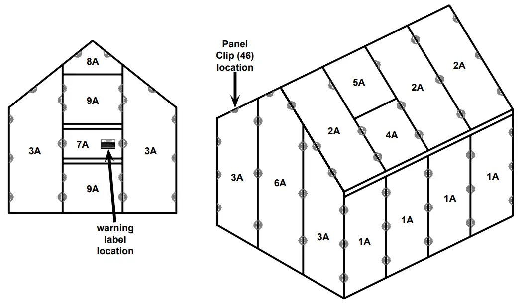


Parts List A- Panels
| Part | Description | Size | Qty |
| 1A | Side Panel | 23.81″ x 47.63″ | 8 |
| 2A | Roof Panel | 23.81″ x 44.48″ | 6 |
| 3A | Front/Rear Panel | 23.81″ x 65.35″ | 4 |
| 4A | Roof Window Pane | 23.81″ x 23.22″ | 2 |
| 5A | Window Pane | 23.62″ x 21.45″ | 2 |
| 6A | Rear Center Panel |
23.81″ x 73.70″ | 1 |
| 7A | Door Center Panel |
23.81″ x 9.44″ | 1 |
| 8A | Top Center Panel |
24.21″ x 9.13″ | 1 |
| 9A | Door Panel | 23.81″ x 23.70″ | 2 |

Record Serial Number Here:
Note: If a product has no serial number, record the month and year of purchase instead.
Note: Some parts are listed and shown for illustration purposes only, and are not available individually as replacement parts. Specify UPC 792363477123 when ordering parts.
![]()
26541 Agoura Road • Calabasas, CA 91302 • 1-888-866-5797
21d
For technical questions, please call 1-888-866-5797.
Item 47712
Safety Instructions
Save This Manual Keep this manual for the safety warnings and precautions, assembly, operating, inspection, maintenance and cleaning procedures. Write the product’s serial number in the back of the manual near the assembly diagram (or month and year of purchase if product has no number). Keep this manual and the receipt in a safe and dry place for future reference.
When unpacking, make sure that the product is intact and undamaged. If any parts are missing or broken, please call 1-888-866-5797 as soon as possible.
![]() WARNING:
WARNING:
Read this material before using this product. Failure to do so can result in serious injury. SAVE THIS MANUAL.
| WARNING SYMBOLS AND DEFINITIONS | |
 |
This is the safety alert symbol. It is used to alert you to potential personal injury hazards. Obey all safety messages that follow this symbol to avoid possible injury or death. |
 |
Indicates a hazardous situation which, if not avoided, will result in death or serious injury. |
 |
Indicates a hazardous situation which, if not avoided, could result in death or serious injury. |
 |
Indicates a hazardous situation which, if not avoided, could result in minor or moderate injury. |
  |
Addresses practices not related to personal injury. |
IMPORTANT SAFETY INFORMATION
![]() WARNING:
WARNING:
Read all safety warnings and instructions.
Failure to follow the warnings and instructions may result in serious injury.
Save all warnings and instructions for future reference.
The warnings, precautions, and instructions discussed in this instruction manual cannot cover all possible conditions and situations that may occur. It must be understood by the operator that common sense and caution are factors which cannot be built into this product, but must be supplied by the operator.
Assembly Precautions
- Do not assemble in windy conditions.
- Assemble and install only on flat, level, hard surface.
- Assemble and anchor only according to these instructions. Improper assembly or inadequate anchoring can create hazards.
- Check for utility lines, tree branches and other structures before assembling.
- Verify that installation surface has no hidden utility lines before anchoring.
- Wear ANSI-approved safety goggles, heavy-duty work gloves and hard hat during assembly and service.
- Keep assembly area clean and well lit.
- Keep bystanders out of the area during assembly.
- Do not assemble when tired or when under the influence of drugs or medication.
- Product capabilities apply to properly and completely assembled product only.
Use Precautions
- CARBON MONOXIDE HAZARD Using an engine inside Shed CAN KILL YOU IN MINUTES. Engine exhaust contains carbon monoxide. This is a poison you cannot see or smell. NEVER use an engine inside Shed, EVEN IF cover is open. Only use an engine OUTSIDE and far away from Shed.
- DO NOT USE IN HIGH WIND. Remove cover if harsh weather or heavy rain threatens.
- For temporary use only.
Do not use for long-term shelter. - Do not use as tent. Does not meet tent flammability standards. Do not use grill, heater, or ignition sources inside or near cover.
- Do not allow snow, rainwater or debris to accumulate or pool on cover.
- Do not hang objects from any part of the Shed.
- This product is not a toy. Do not allow children to play with or near this item.
- Use as intended only.
- Inspect regularly, tighten all loose hardware and loose ropes, and secure all loosened anchors. If any parts are damaged, bent, or stretched, they must be replaced. Hardware may loosen during normal operation stresses.
Loose hardware or damaged/altered parts will compromise the structural integrity of this product. - Maintain product labels and nameplates. These carry important safety information. If unreadable or missing, contact Harbor Freight Tools for a replacement.
![]() SAVE THESE INSTRUCTIONS.
SAVE THESE INSTRUCTIONS.
Symbology
WARNING marking concerning Risk of Eye Injury. Wear ANSI-approved safety goggles with side shields.
Read the manual before assembly and/or use.
WARNING marking concerning
Risk of Head Injury. Wear hard hat during assembly and service.
WARNING marking concerning Risk of Hand Injury. Wear heavy-duty work gloves during assembly and service.
WARNING marking concerning
Risk of Respiratory Injury. Operate engine OUTSIDE and far away from windows, doors, and vents.
Assembly Instructions
![]() Read the ENTIRE IMPORTANT SAFETY INFORMATION section at the beginning of this manual including all text under subheadings therein before set up or use of this product.
Read the ENTIRE IMPORTANT SAFETY INFORMATION section at the beginning of this manual including all text under subheadings therein before set up or use of this product.
![]() WARNING:
WARNING:
TO PREVENT SERIOUS INJURY:
Do not leave this product partially assembled. Assemble this product completely at one time.
Note: At least 3 workers are required for assembly. Before starting assembly, review the instructions and make sure there is enough time and the proper tools available to properly assemble.
Finger tighten all connections until assembly is done. Assemble on a flat, level surface.
Assemble Roof
Note: Unless where otherwise noted, this product’s assembly is done using slip fit construction. Make sure all parts seat completely and securely. A rubber mallet (sold separately) can be used to gently tap parts in place to ensure a tight fit.
- Lay out Roof parts.
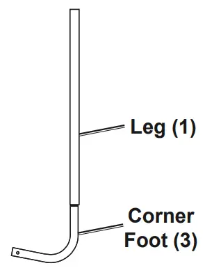
NOTICE: To prevent damage to material, make sure all hardware is installed with Bolts facing cover and Nuts facing inside, away from cover. - Connect Top Rails (4) to 4-Way Center
Connector (11), then connect 3-Way Rail
Connectors (10) to the free end of each rail.

- Connect two Rafters (5) to each Connector, secure Rafters with longer Bolts M6x50 (15) and Nuts (16).
- Connect together:
- 3-Way Corner Connector B (8)
- Top Rail (4)
- 4-Way Center Connector (9)
- Top Rail (4)
- 3-Way Corner Connector A (7).
- Attach assembly to the three Top Rails (5) on one side.
- Repeat on other side.
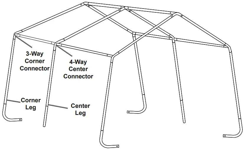
Assemble and Attach Legs
- Assemble four Corner Legs by attaching four Corner Feet (3) to four Legs (1).
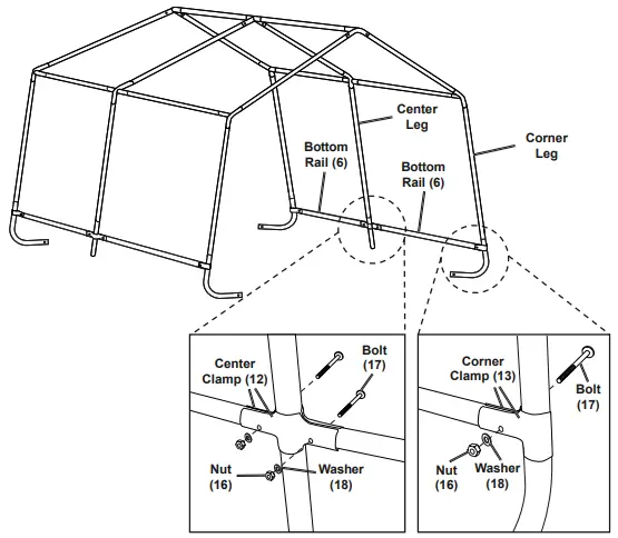
- Assemble two Center Legs by attaching two Center Feet (2) to two Legs (1).
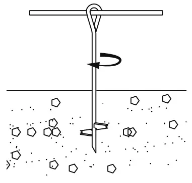
- Attach Corner Legs to 3-Way Corner Connectors. Attach Center Legs to 4-Way Center Connectors
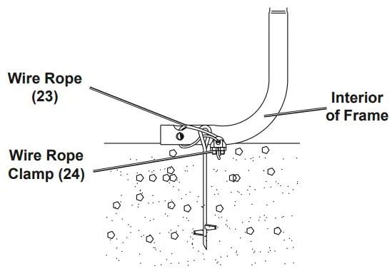
- Connect four Bottom Rails (6) between Center and Corner Legs:
- For Center Legs: Place one Center Clamp (12) on the front and one on the back of the connection. Secure with two sets of shorter Bolts M6x40 (17), Washers (18) and Nuts (16).
- For Corner Legs: Place one Corner Clamp (13) on the front and one on the back of the connection. Secure with one set of shorter Bolts M6x40 (17), Washers (18) and Nuts (16).

Square up the Frame
![]() WARNING:
WARNING:
TO PREVENT SERIOUS INJURY: Contact local utility companies to ensure that the installation area is free of pipes, cables, and other hazards BEFORE choosing installation area or installing anchors.
- Position the frame in the desired location, making sure it is level and flat.
- Measure between diagonal corners. These measurements must be within 1″ of each other.
- Measure across front and back. These measurements must be 10′ each.
- If any measurements do not match, adjust the frame and measure again until measurements match.
Anchor the Frame
WARNING! Anchor only according to these instructions. Improper assembly or inadequate anchoring can create hazards.
CAUTION! To prevent tripping hazard, position Anchors toward the interior of the frame, close to the Corner Feet.
- Use a metal bar (sold separately) to thread the Anchor (14) into the ground, until the loop at the top of the Anchor extends just above the ground.
Note: When anchoring to concrete, use Concrete Anchors (not included).
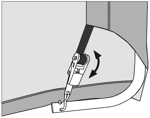
- Insert a Wire Rope (23) through the Anchor and Corner Foot.
- Tighten the Wire Rope and secure it using a Wire Rope Clamp (24). Tighten the nuts on the Clamp evenly

- Repeat on the other corners.
Note: Center Feet may be anchored to increase stability
Attach Front and Back Covers
- Position Front Cover (20) so that zipper pulls are facing toward the outside. Make sure zippers are closed.
- From inside, remove Center Top Rail, then line up top opening on cover with 3-Way Connector. Wrap Cover over tubes so that Strap is under Connector.
- Replace Center Top Rail.
- Repeat with other two Top Rails.

- Thread Strap through Ratchet Tie Down’s (22)spindle. Repeat on other side.

- Hook Ratchet Tie Downs into Corner Feet. Raise and lower the handles to tighten straps, alternating between left and right Feet, until straps are snug.

Attach Roof
- Stretch Top Cover (19) over the frame, making sure it is centered.
- Thread Straps through Ratchet Tie Down’s spindles.
- Hook Ratchet Tie Downs into Corner Feet. Raise and lower the handles to tighten straps slightly, leaving slack in the Top Cover.
- Unzip and roll up Front Cover, securing Cover with hook and eye straps.
- From the inside, on one side of the Shed, remove Clamps from Bottom Rails.
- Remove Bottom Rails, insert Bottom Rails into pockets, then reattach Clamps to Bottom Rails.
- Repeat on other side of Shed.
- Raise and lower the Ratchet Tie Down’s handles, alternating between each corner, until straps are snug.
- Tighten all connections throughout the shed before use.
Do not overtighten.
Maintenance
![]() Procedures not specifically explained in this manual must be performed only by a qualified technician.
Procedures not specifically explained in this manual must be performed only by a qualified technician.
![]() WARNNG:
WARNNG:
TO PREVENT SERIOUS INJURY FROM PRODUCT FAILURE:
Do not use damaged products. If damage is noted, have the problem corrected before further use.
Inspection
MONTHLY, inspect the general condition of the Portable Shed. Check for:
- loose ratchet tie downs, anchors, tube connections, and rail clamps (tighten as needed),
- torn or frayed covers, ropes, or wire ropes,
- cracked, bent, or broken parts, and
- any other condition that may affect its safe operation.
Cleaning
- Immediately remove any accumulated debris from the cover with a broom, mop, or other soft-sided instrument from the outside. DO NOT use sharp instruments.
- PERIODICALLY, clean cover with mild soap and water. DO NOT use bleach or harsh abrasive products.
PLEASE READ THE FOLLOWING CAREFULLY
THE MANUFACTURER AND/OR DISTRIBUTOR HAS PROVIDED THE PARTS LIST IN THIS MANUAL AS A REFERENCE TOOL ONLY. NEITHER THE MANUFACTURER OR DISTRIBUTOR MAKES ANY REPRESENTATION OR WARRANTY OF ANY KIND TO THE BUYER THAT HE OR SHE IS QUALIFIED TO MAKE ANY REPAIRS TO THE PRODUCT, OR THAT HE OR SHE IS QUALIFIED TO REPLACE ANY PARTS OF THE PRODUCT. IN FACT, THE MANUFACTURER AND/OR DISTRIBUTOR EXPRESSLY STATES THAT ALL REPAIRS AND PARTS REPLACEMENTS SHOULD BE UNDERTAKEN BY CERTIFIED AND LICENSED TECHNICIANS, AND NOT BY THE BUYER. THE BUYER ASSUMES ALL RISK AND LIABILITY ARISING OUT OF HIS OR HER REPAIRS TO THE ORIGINAL PRODUCT OR REPLACEMENT PARTS THERETO, OR ARISING OUT OF HIS OR HER INSTALLATION OF REPLACEMENT PARTS THERETO.
]]>Save This Manual Keep this manual for the safety warnings and precautions, assembly, operating, inspection, maintenance, and cleaning procedures. Write the product’s serial number on the back of the manual near the assembly diagram (or month and year of purchase if the product has no number). Keep this manual and the receipt in a safe and dry place for future reference.
21g
![]()

58383
Visit our website at: http://www.harborfreight.com
email our technical support at: [email protected]
email our engine support at: [email protected]
![]() DANGER
DANGER
using an engine indoors Can KiLL yOu in MinuTeS. engine exhaust contains carbon monoxide. This is a poison you cannot see or smell.
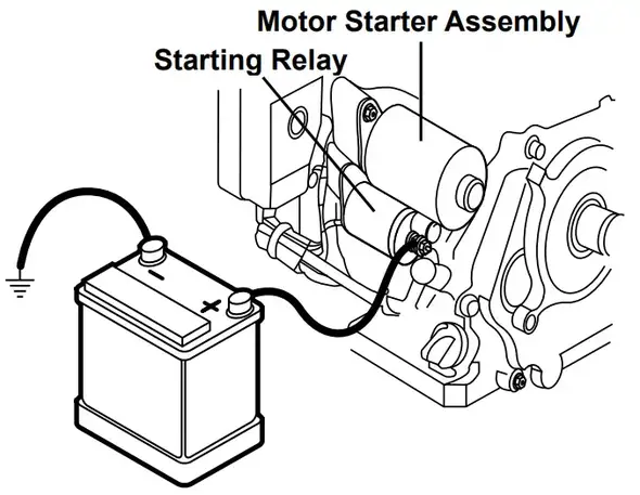 |
|
| NEVER use inside home or garage, EVEN iF doors and windows are open. | Only use OUTSIDE and far away from windows, doors, and vents. |
When unpacking, make sure that the product is intact and undamaged. If any parts are missing or broken, please call 1-888-866-5797 as soon as possible.
Copyright© 2021 by Harbor Freight Tools®. All rights reserved. No portion of this manual or any artwork contained herein may be reproduced in any shape or form without the express written consent of Harbor Freight Tools. Diagrams within this manual may not be drawn proportionally. Due to continuing improvements, the actual product may differ slightly from the product described herein. Tools required for assembly and service may not be included.
![]() WARNING
WARNING
Read this material before using this product. Failure to do so can result in serious injury. SAVE THIS MANUAL.
Specifications
| Displacement | 459 cc | |
| Engine Type | Horizontal Single Cylinder 4 stroke OHV EPA phase III compliant | |
| Cooling System | Forced air-cooled | |
| Starting System | Electric/ Recoil | |
| Fuel | Type | 87+ octane stabilizer treated unleaded gasoline |
| Capacity | 1.85 Gallon | |
| Engine Oil | Type SAE | 10W-30 above 32° F 5W-30 at 32° F or below |
| Capacity | 1.16 Quart | |
| Low Oil Shutdown | Yes | |
| Maximum Horsepower | 15.8 HP @ 3600 RPM | |
| Bore x Stroke | 92 mm x 69 mm | |
| Compression Ratio | 8.8:1 | |
| Rotation viewed from PTO (power takeoff – the output shaft) | Counterclockwise | |
| Shaft | Shaft | 1″ x 3.5″ |
| Keyway | 1/4″ (6.35 mm) | |
| End Tapped | 3/8″– 24 UNF | |
| Spark Plug | Type | NHSP ® / Torch® F7TC |
| Gap | 0.028″– 0.031″ | |
| Valve Clearance | Intake | 0.0020″– 0.0039″ |
| Exhaust | 0.0012″– 0.0031″ | |
| Maximum Speed | No Load | 3800 RPM |
The emission control system for this Engine is warranted for standards set by the U.S. Environmental Protection Agency. For warranty information, refer to the last pages of this manual.
| WARNING SYMBOLS AND DEFINITIONS | |
 |
This is the safety alert symbol. It is used to alert you to potential personal injury hazards. Obey all safety messages that follow this symbol to avoid possible injury or death. |
 |
Indicates a hazardous situation which, if not avoided, will result in death or serious injury. |
 |
Indicates a hazardous situation which, if not avoided, could result in death or serious injury. |
| Indicates a hazardous situation which, if not avoided, could result in minor or moderate injury. | |
| NOTICE CAUTION |
Addresses practices not related to personal injury. |
Symbol Definitions
| Symbol | Property or Statement |
| RPM | Revolutions Per Minute |
| HP | Horsepower |
 |
WARNING marking concerning Risk of Eye Injury. Wear ANSI-approved safety goggles with side shields. |
| Read the manual before set-up and/or use. | |
 |
WARNING marking concerning Risk of Hearing Loss. Wear hearing protection. |
| Symbol | Property or Statement |
 |
WARNING marking concerning Risk of Respiratory Injury. Operate engine OUTSIDE and far away from windows, doors, and vents. |
 |
WARNING marking concerning Risk of Fire while handling fuel. Do not smoke while handling fuel. |
 |
WARNING marking concerning Risk of Fire. Do not refuel while operating. Keep flammable objects away from engine. |
Safety Warnings
![]() WarninG! read all instructions.
WarninG! read all instructions.
Failure to follow all instructions listed below may result in fire, serious injury, and/or DeaTH. The warnings and precautions discussed in this manual cannot cover all possible conditions and situations that may occur. It must be understood by the operator that common sense and caution are factors that cannot be built into this product but must be supplied by the operator.
SAVE THESE INSTRUCTIONS
Set up precautions
- Gasoline fuel and fumes are flammable and potentially explosive. Use proper fuel storage and handling procedures. Do not store fuel or other flammable materials nearby.
- Have multiple ABC class fire extinguishers nearby.
- Operation of this equipment may create sparks that can start fires around dry vegetation. A spark arrestor may be required. The operator should contact local fire agencies for laws or regulations relating to fire prevention requirements.
- Set up and use only on a flat, level, well-ventilated surface.
- Wear ANSI-approved safety goggles, heavy-duty work gloves, and dust mask/respirator during setup.
- Use only lubricants and fuel recommended in the Specifications chart of this manual.
Operating precautions
 CARBON MONOXIDE HAZARD Using an engine indoors CAN KILL YOU IN MINUTES. Engine exhaust contains carbon monoxide. This is a poison you cannot see or smell.
 NEVER use it inside a home or garage, EVEN IF doors and windows are open.
Only use OUTSIDE and far away from windows, doors, and vents.- Keep children away from the equipment, especially while it is operating.
- Keep all spectators at least six feet from the Engine during operation.
- Fire Hazard! Do not fill the gas tank while the engine is running. Do not operate if gasoline has been spilled. Clean spilled gasoline before starting the engine. Do not operate near pilot light or open flame.
- Do not touch the engine during use. Let the engine cool down after use.
- Never store fuel or other flammable materials near the engine.
- Only use a suitable means of transport and lifting devices with sufficient weight-bearing capacity when transporting the Engine.
- Secure the Engine on transport vehicles to prevent the tool from rolling, slipping, and tilting.
- Industrial applications must follow OSHA requirements.
- Do not leave the equipment unattended when it is running. Turn off the equipment (and remove safety keys, if available) before leaving the work area.
- Engine can produce high noise levels. Prolonged exposure to noise levels above 85 dBA is hazardous to hearing. Always wear ear protection when operating or working
around the gas engine while it is operating. - Wear ANSI-approved safety glasses, hearing protection, and NIOSH-approved dust mask/ respirator under a full face shield along with steel-toed work boots during use.
- People with pacemakers should consult their physician(s) before use. Electromagnetic fields in close proximity to a heart pacemaker could cause pacemaker interference or pacemaker failure. Caution is necessary when near the engine’s magneto or recoil starter.
- Use only accessories that are recommended by Harbor Freight Tools for your model. Accessories that may be suitable for one piece of equipment may become hazardous
when used on another piece of equipment. - Do not operate in explosive atmospheres, such as in the presence of flammable liquids, gases, or dust. Gasoline-powered engines may ignite the dust or fumes.
- Stay alert, watch what you are doing, and use common sense when operating this piece of equipment. Do not use this piece of equipment while tired or under the influence of drugs, alcohol, or medication.
- Do not overreach. Keep proper footing and balance at all times. This enables better control of the equipment in unexpected situations.
- Use this equipment with both hands only. Using equipment with only one hand can easily result in loss of control.
- Dress properly. Do not wear loose clothing or jewelry. Keep hair, clothing, and gloves away from moving parts. Loose clothes, jewelry, or long hair can be caught in moving parts.
- Parts, especially exhaust system components, get very hot during use. Stay clear of hot parts.
- Do not cover the engine or equipment during operation.
- Keep the equipment, engine, and surrounding area clean at all times.
- Do not refill the fuel tank while the engine is running or hot.
- Use the equipment, accessories, etc., in accordance with these instructions and in the manner intended for the particular type of equipment, taking into account the working
conditions and the work to be performed. Use of the equipment for operations different from those intended could result in a hazardous situation. - Do not operate the equipment with known leaks in the engine’s fuel system.
- When spills of fuel or oil occur, they must be cleaned up immediately. Dispose of fluids and cleaning materials as per any local, state, or federal codes and regulations. Store oil rags in a bottom-ventilated, covered, metal container.
- Keep hands and feet away from moving parts. Do not reach over or across equipment while operating.
- Before use, check for misalignment or binding of moving parts, breakage of parts, and any other condition that may affect the equipment’s operation. if damaged, have the equipment serviced before using. Many accidents are caused by poorly maintained equipment.
- Use the correct equipment for the application. Do not modify the equipment and do not use the equipment for a purpose for which it is not intended.
Service precautions
- Before service, maintenance, or cleaning:
a. Turn the engine switch to its “OFF” position.
b. allow the engine to completely cool.
c. Then, remove the spark plug cap from the spark plug. - Keep all safety guards in place and in proper working order. Safety guards include mufflers, air cleaners, mechanical guards, and heat shields, among other guards.
- Do not alter or adjust any part of the equipment or its engine that is sealed by the manufacturer or distributor. Only a qualified service technician may adjust parts that may increase or decrease governed engine speed.
- Wear ANSI-approved safety goggles, heavy-duty work gloves, and a dust mask/respirator during service.
- Maintain labels and nameplates on the equipment. These carry important information. If unreadable or missing, contact Harbor Freight Tools for a replacement.
- Have the equipment serviced by a qualified repair person using only identical replacement parts. This will ensure that the safety of the equipment is maintained. Do not attempt any service or maintenance procedures not explained in this manual or any procedures that you are uncertain about your ability to perform safely or correctly.
- Store equipment out of the reach of children.
- Follow scheduled engine and equipment maintenance.
Refueling:
- Do not refill the fuel tank while the engine is running or hot.
- Do not smoke, or allow sparks, flames, or other sources of ignition around the equipment, especially when refueling.
- Do not fill the fuel tank to the top. Leave a little room for the fuel to expand as needed.
- Refuel in a well-ventilated area only.
- Wipe up any spilled fuel and allow excess to evaporate before starting the engine. To prevent Fire, do not start the engine while the smell of fuel hangs in the air.
![]() SAVE THESE INSTRUCTIONS
SAVE THESE INSTRUCTIONS
Set up
![]() Read the ENTIRE IMPORTANT SAFETY INFORMATION section at the beginning of this manual including all text under subheadings therein before set up or use of this product.
Read the ENTIRE IMPORTANT SAFETY INFORMATION section at the beginning of this manual including all text under subheadings therein before set up or use of this product.
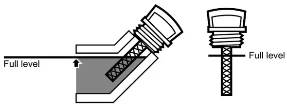
TO PREVENT SERIOUS INJURY:
Operate only with a proper spark arrestor installed.
![]() Operation of this equipment may create sparks that can start fires around dry vegetation. a spark arrestor may be required.
Operation of this equipment may create sparks that can start fires around dry vegetation. a spark arrestor may be required.
The operator should contact local fire agencies for laws or regulations relating to fire prevention requirements.
WarninG! TO preVenT SeriOuS inJury: DO nOT inSTaLL THiS enGine On a VeHiCLe.
WarninG! inSTaLL THiS enGine aCCOrDinG TO eQuipMenT inSTruCTiOnS BeFOre uSe.
WarninG! TO preVenT SeriOuS inJury: if you do not connect a battery to the positive battery cable, wrap its terminal securely with electrical tape (sold separately).
At high altitudes, the Engine’s carburetor, governor (if so equipped), and any other parts that control the fuel-air ratio will need to be adjusted by a qualified mechanic to allow efficient high-altitude use and to prevent damage to the engine and any other devices used with this product.
Battery Setup instructions
- Place a fully charged, lead-acid 12 volt, 300 CCa, 36 ah battery (not included) in a stable, flat location near the engine.
- Only use cables sized to match their length according to the following chart:
Cable Gauge (lower gauge numbers mean thicker cables) Maximum Cable Length 6 5′ 4 7′ 2 12′ 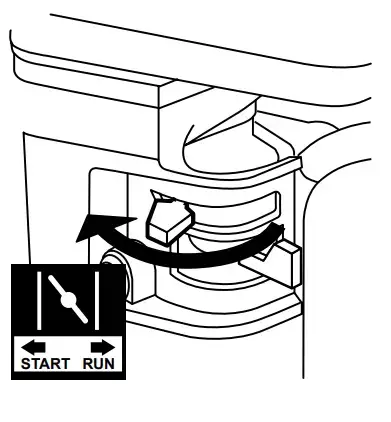
- Attach the positive cable from the positive battery terminal to the Positive Terminal on the starter solenoid (uncovered terminal), as shown above. Connect cable securely to
prevent disconnection and short circuits. - Attach the negative cable to the negative battery terminal.
- Connect the negative cable securely to one of the engine mounting bolts, as shown in the diagram below. Connect cable securely to prevent disconnection and short circuits.
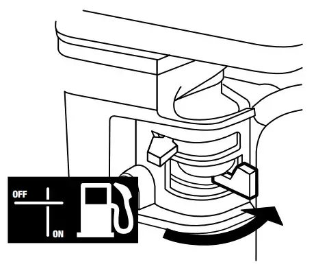
- Coat the terminals and cable ends with a corrosion-preventive coating.
Engine Controls
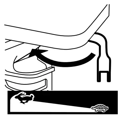
Operation
![]() Read the ENTIRE IMPORTANT SAFETY INFORMATION section at the beginning of this manual including all text under subheadings therein before setting up or use of this product.
Read the ENTIRE IMPORTANT SAFETY INFORMATION section at the beginning of this manual including all text under subheadings therein before setting up or use of this product.
Pre-Start Checks
Inspect engine and equipment looking for damaged, loose, and missing parts before setting up and starting. If any problems are found, do not use equipment until fixed properly.
Checking and Filling Engine Oil
NOTICE: Your Warranty is VOID if the engine’s crankcase is not properly filled with oil before each use. Before each use, check the oil level. Engine will not start with low or no engine oil.
- Make sure the engine is stopped and is level.
- Close the Fuel Valve.
- Clean the top of the Dipstick and the area around it. Remove the Dipstick by turning it counterclockwise, and wipe it off with a clean, lint-free rag.

- Reinsert the Dipstick without threading it in and remove it to check the oil level. The oil level should be up to the full level as shown above.
- If the oil level is at or below the low mark add the appropriate type of oil until the oil level is at the proper level. SAE 10W-30 oil is recommended for general use. (The SAE Viscosity Grade chart on page 13 in the Maintenance section shows other viscosities to use in different average temperatures.)
- Thread the dipstick back in clockwise.
NOTICE: Do not run the engine with too little oil. Engine will shut off if engine oil level is too low.
Checking and Filling Fuel
![]() WARNING! TO PREVENT SERIOUSLY INJURY FROM FIRE:
WARNING! TO PREVENT SERIOUSLY INJURY FROM FIRE:
 Fill the fuel tank in a well-ventilated area away from ignition sources. If the engine is hot from use, shut the engine off and wait for it to cool before adding fuel. Do not smoke.
- Clean the Fuel Cap and the area around it.
- Unscrew and remove the Fuel Cap.
- If needed, fill the Fuel Tank to about 1 inch under the fill neck with 87 octanes or higher unleaded gasoline that has been treated with a fuel stabilizer additive. Follow fuel stabilizer manufacturer’s recommendations for use.
Note: Do not use gasoline containing more than 10% ethanol (E10). Do not use E85 ethanol.
Note: Do not use gasoline that has been stored in a metal fuel container or a dirty fuel container. It can cause particles to enter the carburetor, affecting engine performance and/or causing damage. - Then replace the Fuel Cap.
- Wipe up any spilled fuel and allow excess to evaporate before starting the engine.
To prevent FIRE, do not start the engine while the smell of fuel hangs in the air.
Starting the Engine
![]() Before starting the engine
Before starting the engine
Before starting the engine:
a. Follow the Setup instructions in the equipment manual to prepare the equipment.
b. inspect the equipment and engine.
c. Fill the engine with the proper amount and type of both stabilizer-treated unleaded gasoline and oil.
d. read the equipment Operation section in the equipment manual.
- To start a cold engine, move the Choke Lever to the START position. To restart a warm engine, leave the Choke Lever in the RUN position.

- Open the Fuel Valve.
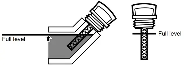
- Slide the Throttle or Speed Control Lever to 1/3 away from the SLOW position (the “turtle”).
 Note: Some tools have a Speed Control Lever located elsewhere on the tool which functions the same as the Throttle. Use the Speed Control Lever in place of the Throttle when the tool is so equipped.
 - For ManuaL START
A. Turn the Engine Switch to ON.
B. Grip the Starter Handle of the Engine loosely and pull it slowly several times to allow the gasoline to flow into the Engine’s carburetor. Then pull the Starter Handle gently until resistance is felt. Allow Cable to retract fully and then pull it quickly. Repeat until the Engine starts. Note: Do not let the Starter Handle snap back against the Engine. Hold it as it recoils so it doesn’t hit the Engine.
Note: If the Engine does not start, check the engine oil level. Engine will not start with low or no engine oil.
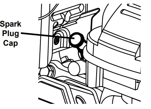
For ELECTRIC START
Turn the Engine Switch to START.

Note: To prolong starter life, use short starting cycles (5 seconds maximum). Then wait one minute before attempting to start again.
5. Allow the Engine to run for several seconds. Then, if the Choke Lever is in the START position, move the Choke Lever very slowly to its RUN position.
Note: Moving the Choke Lever too fast could stall the engine.
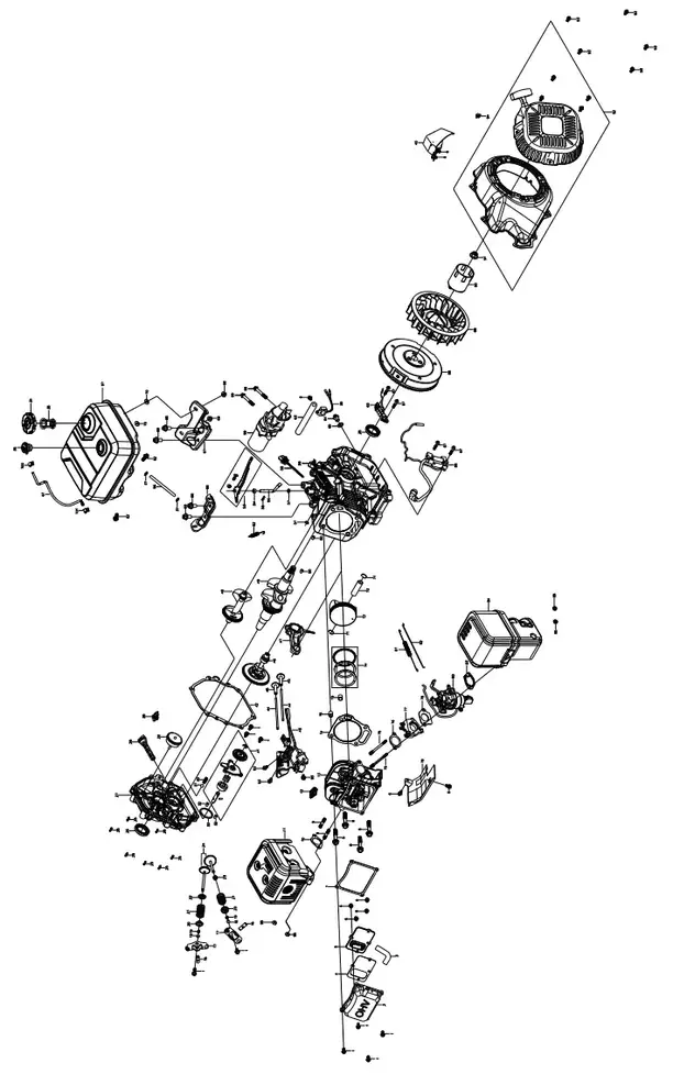
IMPORTANT: Allow the engine to run at no load for five minutes with no
load after each start‑up so that the engine can stabilize.
6. Adjust the Throttle as needed.
7. Break-in Period:
a. Breaking in the engine will help to ensure proper equipment and engine operation.
b. The operational break-in period will last about 3 hours of use. During this period:
• Do not apply a heavy load to the equipment.
• Do not operate the engine at its maximum speed.
c. The maintenance break-in period will last about 20 hours of use. After this period:
• Change the engine oil.
Under normal operating conditions subsequent maintenance follows the schedule explained in the MAINTENANCE AND SERVICING section.
- To stop the engine in an emergency, turn the Engine Switch OFF.
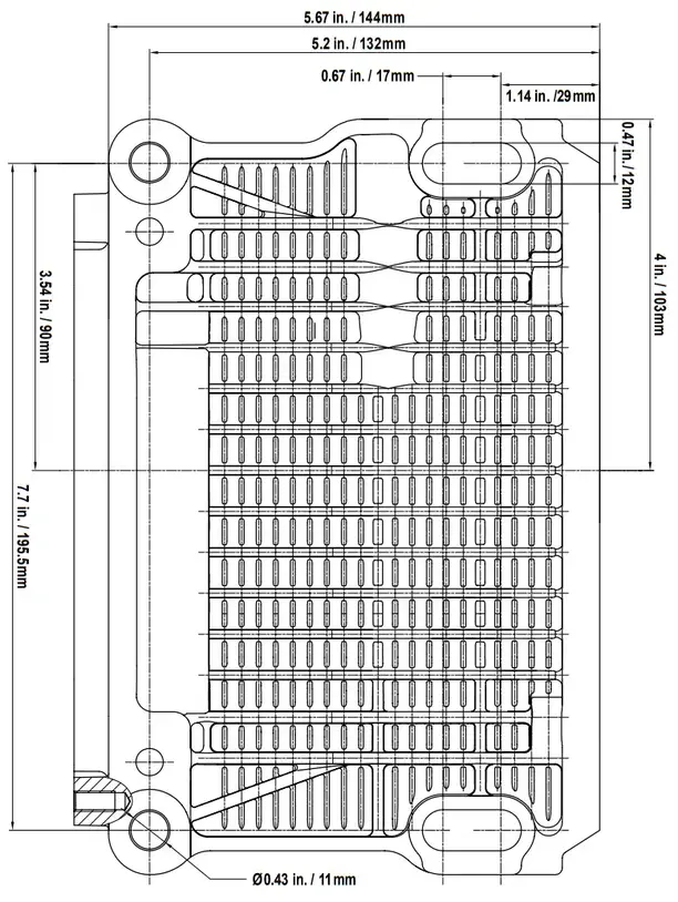
- Under normal conditions, use the following procedure:
a. Slide the Throttle or Speed Control A lever to SLOW (the “turtle”).
b. Turn the Engine Switch OFF.
c. Close the Fuel Valve.
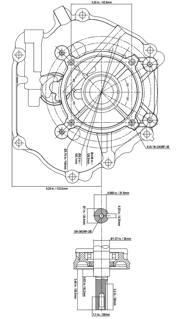
Maintenance
![]() WARNING
WARNING
TO PREVENT SERIOUS INJURY FROM ACCIDENTAL STARTING:
Turn the Power Switch of the equipment to its “OFF” position, wait for the engine to cool, and disconnect the spark plug cap before performing any inspection, maintenance, or cleaning procedures.
TO PREVENT SERIOUS INJURY FROM EQUIPMENT FAILURE:
Do not use damaged equipment. If abnormal noise, vibration, or excess smoking occurs, have the problem corrected before further use.
Follow all service instructions in this manual. The engine may fail critically if not serviced properly.
Many maintenance procedures, including any not detailed in this manual, will need to be performed by a qualified technician for safety. If you have any doubts about your ability to safely service the equipment or engine, have a qualified technician service the equipment instead.
![]() Many maintenance procedures, including any not detailed in this manual, will need to be performed by a qualified technician for safety. if you have any doubts about your ability to safely service the equipment or engine, have a qualified technician service the equipment instead.
Many maintenance procedures, including any not detailed in this manual, will need to be performed by a qualified technician for safety. if you have any doubts about your ability to safely service the equipment or engine, have a qualified technician service the equipment instead.
Cleaning, Maintenance, and Lubrication Schedule
Note: This maintenance schedule is intended solely as a general guide. If performance decreases or if equipment operates unusually, check systems immediately. The maintenance needs of each piece of equipment will differ depending on factors such as duty cycle, temperature, air quality, fuel quality, and other factors.
Note: The following procedures are in addition to the regular checks and maintenance explained as part of the regular operation of the engine and equipment.
| Procedure | Before Each Use | Monthly or every 20
hr. of use |
Every 3 mo. or 50 hr. of use | Every 6 mo. or 100 hr. of use | Yearly or every 300
hr. of use |
Every 2 Years |
| Brush off outside of engine | ✓ | ✓ | ✓ | ✓ | ✓ | ✓ |
| Check engine oil level | ✓ | ✓ | ✓ | ✓ | ✓ | ✓ |
| Check air cleaner | ✓ | ✓ | ✓ | ✓ | ✓ | |
| Check deposit cup | ✓ | ✓ | ✓ | ✓ | ||
| Change engine oil | ✓ | ✓ | ✓ | ✓ | ||
| Clean/replace air cleaner | ✓* | ✓ | ✓ | ✓ | ||
| Check and clean spark plug | ✓ | ✓ | ✓ | |||
| 1. Check/adjust the idle speed 2. Check/adjust valve clearance 3. Clean fuel tank, strainer, and carburetor 4. Clean carbon build-up from the combustion chamber |
✓** | ✓** | ||||
| Replace fuel line if necessary | ✓** |
*Service more frequently when used in dusty areas.
**These items should be serviced by a qualified technician.
Checking and Filling Fuel
![]() WARNING! TO PREVENT SERIOUS INJURY FROM FIRE:
WARNING! TO PREVENT SERIOUS INJURY FROM FIRE:
 Fill the fuel tank in a well-ventilated area away from ignition sources. If the engine is hot from use, shut the engine off and wait for it to cool before adding fuel. Do not smoke.
- Clean the Fuel Cap and the area around it.
- Unscrew and remove the Fuel Cap.
- If needed, fill the Fuel Tank to about 1 inch under the fill neck with 87 octanes or higher unleaded gasoline that has been treated with a fuel stabilizer additive. Follow fuel stabilizer manufacturer’s recommendations for use.
Note: Do not use gasoline containing more than 10% ethanol (E10). Do not use E85 ethanol.
Note: Do not use gasoline that has been stored in a metal fuel container or a dirty fuel container. It can cause particles to enter the carburetor, affecting engine performance and/or causing damage. - Then replace the Fuel Cap.
- Wipe up any spilled fuel and allow excess to evaporate before starting engine. To prevent FIRE, do not start the engine while the smell of fuel hangs in the air.
Engine Oil Change
![]() CAUTION! Oil is very hot during operation and can cause burns. Wait for the engine to cool before changing the oil.
CAUTION! Oil is very hot during operation and can cause burns. Wait for the engine to cool before changing the oil.
- Make sure the engine is stopped and is level.
- Close the Fuel Valve.
- Place a drain pan (not included) underneath the crankcase’s drain plug.
- Remove the drain plug and, if possible, tilt the crankcase slightly to help drain the oil out. Recycle used oil.
- Replace the drain plug and tighten it.
- Clean the top of the Dipstick and the area around it. Remove the Dipstick by turning it counterclockwise, and wipe it off with a clean, lint-free rag.

- Add the appropriate type of oil until the oil level is at the full level. SAE 10W-30 oil is recommended for general use. The SAE Viscosity Grade chart shows other viscosities to use in different average temperatures.

- Thread the dipstick back in clockwise.
NOTICE: Do not run the engine with too little oil. Engine will not start with low or no engine oil.
Air Filter Element Maintenance
- Remove the air filter cover and the air filter elements
and check for dirt. Clean as described below. - Cleaning:
• For “paper” filter elements:
To prevent injury from dust and debris, wear ANSI-approved safety goggles,
NIOSH‑approved dust mask/respirator, and heavy-duty work gloves. In a well-ventilated area away from bystanders, use pressurized air to blow dust out of the air filter.
• For foam filter elements: Wash the element in warm water and mild detergent several times. Rinse. Squeeze out excess water and allow it to dry completely. Soak the filter in lightweight oil briefly, then squeeze out the excess oil. - Install the cleaned filter. Secure the Air Cleaner Cover before use.
Spark Plug Maintenance

- Spark Plug Maintenance Spark Plug Cap Disconnect the spark plug cap from the end of the plug. Clean out debris from around the spark plug.
- Using a spark plug wrench, remove the spark plug.
- Inspect the spark plug:
If the electrode is oily, clean it using a clean, dry rag. If the electrode has been deposited on it, polish it using emery paper. If the white insulator is cracked or chipped, the spark plug needs to be replaced. Use only NHSP ® / Torch® F7TC spark plug.
NOTICE: Using an incorrect spark plug may damage the engine. - When installing a new spark plug, adjust the plug’s gap to the specification on the Technical Specifications chart. Do not pry against the electrode, the spark plug can be damaged.
- Install the new spark plug or the cleaned spark plug into the engine. Gasket-style: Finger-tighten until the gasket contacts the cylinder head, then tighten about 1/2-2/3 turn more.
Non-gasket-style: Finger-tighten until the plug contacts the head, then tighten about 1/16 turn more.
NOTICE: Tighten the spark plug properly. If loose, the spark plug will cause the engine to overheat. If overtightened, the threads in the engine block will be damaged. - Apply dielectric spark plug boot protector (not included) to the end of the spark plug and reattach the wire securely.
Storage
When the equipment is to remain idle for longer than 20 days, prepare the Engine for storage as follows:
- CLEANING:
Wait for the Engine to cool, then clean the Engine with a dry cloth. NOTICE: Do not clean using water. The water will gradually enter the Engine and cause rust damage. Apply a thin coat of rust preventive oil to all metal parts. - FUEL:
Gasoline Treatment / Draining the Fuel Tank
• To protect the Fuel Tank during storage, fill the tank with fresh gasoline that has been treated with a fuel stabilizer additive. Follow fuel stabilizer manufacturer’s
recommendations for use. Refer to “Checking and Filling Fuel” on page 13.
• Aged gasoline that has not been treated with a stabilizer ahead of time must be safely drained away and not run through the Engine.
 WARNING! TO PREVENT SERIOUS INJURY FROM FIRE:
 Drain the Fuel Tank in a well-ventilated area away from ignition sources. If the engine is hot from use, shut the engine off and wait for it to cool before adding fuel.
Do not smoke. Draining the Carburetor
• After closing the Fuel Valve, place an appropriate container under the Carburetor and carefully remove the Drain Bolt from the bottom of the Carburetor Bowl, allowing the fuel to drain completely. Replace the Drain Bolt after draining.
WARNING! To prevent seriously injury and fire, close the Fuel Valve before draining the Carburetor.
LUBRICATION:
a. Change engine oil.
b. Clean out the area around the spark plug.
Remove the spark plug and pour one tablespoon of
engine oil into the cylinder through the spark plug hole.
c. Replace spark plug, but leave spark plug cap disconnected.
d. Pull Starter Handle to distribute oil in the cylinder. Stop after one or two revolutions when you feel the piston start the compression stroke (when you start to feel resistance). - BATTERY:
Disconnect battery cables (if equipped). Disconnect the negative battery cable first, then the positive battery cable. Recharge batteries monthly while in storage. - STORAGE AREA:
Cover and store in a dry, level, well-ventilated area out of reach of children. Storage area should also be away from ignition sources, such as water heaters, clothes dryers, and furnaces.
NOTICE: During extended storage periods the Engine must be started every 3 months and allowed to run for 15 – 20 minutes or the Warranty is VOID. - AFTER STORAGE:
Before starting the Engine during or after storage, keep in mind that untreated gasoline will deteriorate quickly. Drain the fuel tank and change to fresh fuel if untreated
gasoline has been sitting for a month, if treated gasoline has been sitting beyond the fuel stabilizer’s recommended time period, or if the Engine does not start.
Troubleshooting
| Problem | Possible Causes | Probable Solutions |
| Engine will not start | FUEL RELATED:
1. No fuel in tank or fuel valve closed. |
FUEL RELATED:
1. Fill fuel tank with fresh 87+ octane stabilizer- treated unleaded gasoline and open fuel valve. |
| IGNITION (SPARK) RELATED: 1. Engine switch in OFF position. 2. Spark plug cap not connected securely. 3. Spark plug electrode wet or dirty. 4. Incorrect spark plug gap. 5. Spark plug cap is broken. 6. Circuit breaker tripped. 7. Incorrect spark timing or faulty ignition system. |
IGNITION (SPARK) RELATED: 1. Turn engine switch to ON position. 2. Connect the spark plug cap properly. 3. Clean spark plug. 4. Correct spark plug gap. 5. Replace spark plug cap. 6. Reset circuit breaker. Check wiring and starter motor if the breaker continues to trip. 7. Have a qualified technician diagnose/ repair the ignition system. |
|
| COMPRESSION RELATED: 1. Cylinder not lubricated. Problem after long storage periods. 2. Loose or broken spark plug. (Hissing noise will occur when trying to start.) 3. Lose cylinder head or damaged head gasket. (Hissing noise will occur when trying to start.) 4. Engine valves or tappets are misadjusted or stuck. |
COMPRESSION RELATED: 1. Pour a tablespoon of oil into the spark plug hole. Crank the engine a few times and try to start again. 2. Tighten spark plug. If that does not work, replace the spark plug. If the problem persists, may have a head gasket problem — see #3. 3. Tighten head. If that does not remedy the problem, replace the head gasket. 4. Have a qualified technician adjust/ repair valves and tappets. |
|
| ENGINE OIL-RELATED: 1. Low engine oil. 2. Engine mounted on the slope, triggering low oil shutdown. |
ENGINE OIL-RELATED: 1. Fill engine oil to the proper level. Check engine oil before EVERY use. 2. Operate the engine on a level surface. Check engine oil level. |
![]() Follow all safety precautions whenever diagnosing or servicing the equipment or engine.
Follow all safety precautions whenever diagnosing or servicing the equipment or engine.
| Problem | Possible Causes | Probable Solutions |
| Engine misfires | 1. Spark plug cap loose. 2. Incorrect spark plug gap or damaged spark plug. 3. Defective spark plug cap. 4. Old or low-quality gasoline. 5. Incorrect compression. |
1. Check cap and wire connections. 2. Re-gap or replace spark plug. 3. Replace spark plug cap. 4. Use only fresh 87+ octane stabilizer-treated unleaded gasoline. Do not use gasoline with more than 10% ethanol (E15, E20, E85, etc.). 5. Diagnose and repair compression. (Use Engine will not start: COMPRESSION RELATED section.) |
| Engine stops suddenly | 1. Fuel tank empty or full of impure or low-quality gasoline. 2. Low oil shutdown. 3. Defective fuel tank cap creating a vacuum, preventing proper fuel flow. 4. Faulty magneto. 5. Disconnected or improperly connected spark plug cap. |
1. Fill fuel tank with fresh 87+ octane stabilizer-treated unleaded gasoline. Do not use gasoline with more than 10% ethanol (E15, E20, E85, etc.). 2. Fill engine oil to a proper level. Check engine oil before EVERY use. 3. Test/replace fuel tank cap. 4. Have qualified technician service magneto. 5. Secure spark plug cap. |
| Engine stops when under heavy load | 1. Dirty air filter 2. Engine running cold. |
1. Clean element. 2. Allow engine to warm up prior to operating equipment. |
| Engine knocks | 1. Old or low-quality gasoline. 2. Engine overloaded. 3. Incorrect spark timing, deposit buildup, worn engine, or other mechanical problems. |
1. Fill fuel tank with fresh 87+ octane stabilizer-treated unleaded gasoline. Do not use gasoline with more than 10% ethanol (E15, E20, E85, etc.). 2. Do not exceed the equipment’s load rating. 3. Have qualified technicians diagnose and service the engine. |
| Engine backfires | 1. Impure or low-quality gasoline. 2. Engine too cold. 3. Intake valve stuck or an overheated engine. 4. Incorrect timing. |
1. Fill fuel tank with fresh 87+ octane stabilizer-treated unleaded gasoline. Do not use gasoline with more than 10% ethanol (E15, E20, E85, etc.). 2. Use cold-weather fuel and oil additives to prevent backfiring. 3. Have qualified technicians diagnose and service the engine. 4. Check engine timing. |
| After sudden impact, engine will run, but the equipment will not operate | Shaft key or other shear pin is broken by impact to disconnect engine and limit damage. | Have a qualified technician check and replace the broken shaft key or other shear pins. |
![]() Follow all safety precautions whenever diagnosing or servicing the equipment or engine.
Follow all safety precautions whenever diagnosing or servicing the equipment or engine.
PLEASE READ THE FOLLOWING CAREFULLY
THE MANUFACTURER AND/OR DISTRIBUTOR HAS PROVIDED THE PARTS LIST AND ASSEMBLY DIAGRAM IN THIS MANUAL AS A REFERENCE TOOL ONLY. NEITHER THE MANUFACTURER NOR DISTRIBUTOR MAKES ANY REPRESENTATION OR WARRANTY OF ANY KIND TO THE BUYER THAT HE OR SHE IS QUALIFIED TO MAKE ANY REPAIRS TO THE PRODUCT, OR THAT HE OR SHE IS QUALIFIED TO REPLACE ANY PARTS OF THE PRODUCT. IN FACT, THE MANUFACTURER AND/OR DISTRIBUTOR EXPRESSLY STATE THAT ALL REPAIRS AND PARTS REPLACEMENTS SHOULD BE UNDERTAKEN BY CERTIFIED AND LICENSED TECHNICIANS, AND NOT BY THE BUYER. THE BUYER ASSUMES ALL RISK AND LIABILITY ARISING OUT OF HIS OR HER REPAIRS TO THE ORIGINAL PRODUCT OR REPLACEMENT PARTS THERETO OR ARISING OUT OF HIS OR HER INSTALLATION OF REPLACEMENT PARTS THERETO.
Parts List and Diagrams
Parts List
| Part | Description | Qty. | Part | Description | Qty. | |
| 1 | Flange Hex Bolt | 9 | 52 | Governor Spring | 1 | |
| 2 | Cylinder Head Cover | 1 | 53 | Speed Regulating Bracket | 1 | |
| 3 | Breather Tube | 1 | 54 | Oil Seal | 1 | |
| 4 | Breather Chamber Packing | 1 | 55 | Pin Clip | 1 | |
| 5 | Breather Chamber Cap | 1 | 56 | Speed Regulating Arm | 1 | |
| 6 | Flange Hex Bolt | 8 | 57 | Flat Washer | 1 | |
| 7 | Cylinder Head Cover Gasket | 1 | 58 | Oil Dipstick | 1 | |
| 8 | Flange Hex Bolt | 4 | 59 | Crankcase Body | 1 | |
| 9 | Stud | 2 | 60 | Charging Current Armature | 1 | |
| 10 | Outlet Gasket | 1 | 61 | Breather Tube | 1 | |
| 11 | Muffler | 1 | 62 | Flange Hex Bolt | 2 | |
| 12 | Spark Plug | 1 | 63 | Cable Cleat | 1 | |
| 13 | Cylinder Head | 1 | 64 | Oil Drain Bolt | 1 | |
| 14 | Cylinder Head Gasket | 1 | 65 | Flat Washer | 1 | |
| 15 | Pin | 2 | 66 | Fuel Tank Bracket | 1 | |
| 16 | Valve Rocker Shaft | 2 | 67 | Fuel Tank Bracket | 1 | |
| 17 | Valve Rocker | 2 | 68 | Flange Hex Bolt | 4 | |
| 18 | Valve Adjustment Cap | 2 | 69 | Hex Flange Nut | 2 | |
| 19 | Valve Lock | 4 | 70 | Rubber Gasket | 2 | |
| 20 | Valve Spring Retainer | 2 | 71 | Piston Pin Clip | 2 | |
| 21 | Valve Spring | 2 | 72 | Piston | 1 | |
| 22 | Valve Spring Seat | 1 | 73 | Piston Pin | 1 | |
| 23 | Valve Oil Seal | 1 | 74 | Piston Ring Set | 1 | |
| 24 | Valve Set | 1 | 75 | Stud | 2 | |
| 25 | Flange Hex Bolt | 7 | 76 | Carburetor Gasket | 1 | |
| 26 | Oil Seal | 2 | 77 | Carburetor Heat Insulating Pad | 1 | |
| 27 | Crankcase Cover | 1 | 78 | Carburetor Gasket | 1 | |
| 28 | Engine Oil Strainer | 1 | 79 | Air Deflector | 1 | |
| 29 | Governor Gear | 1 | 80 | Carburetor | 1 | |
| 30 | Compression Spring | 1 | 81 | Throttle Return Spring | 1 | |
| 31 | Steel Ball | 1 | 82 | Throttle Rod | 1 | |
| 32 | Pin | 2 | 83 | Carburetor Gasket | 1 | |
| 33 | Seal Ring | 1 | 84 | Air Filter | 1 | |
| 34 | Fuel Tank Cap | 1 | 85 | Hex Flange Nut | 2 | |
| 35 | Fuel Strainer | 1 | 86 | Ignition Coil | 1 | |
| 36 | Fuel Tank Breather Valve | 1 | 87 | Flange Hex Bolt | 5 | |
| 37 | Hose Clip | 2 | 88 | Flywheel Assembly | 1 | |
| 38 | Oil Level Alarm | 1 | 89 | Impeller | 1 | |
| 39 | Engine Oil Protector | 1 | 90 | Starter Pulley | 1 | |
| 40 | Starter Control Box | 1 | 91 | Hex Flange Nut | 1 | |
| 41 | Oil Pump Components | 1 | 92 | Manual Starting Assembly | 1 | |
| 42 | Crankcase Cover Gasket | 1 | 93 | Flange Hex Bolt | 8 | |
| 43 | Throttle Handle Assembly | 1 | 94 | Wire Clip | 1 | |
| 44 | Push Rod | 2 | 95 | Nut | 2 | |
| 45 | Valve Lifter | 2 | 96 | Fuel Hose | 1 | |
| 46 | Camshaft Assembly | 1 | 97 | Fuel Tank | 1 | |
| 47 | Connecting Rod | 1 | 98 | Starter Motor | 1 | |
| 48 | Balancing Shaft Assembly | 1 | 99 | Flange Hex Bolt | 2 | |
| 49 | Crankshaft | 1 | 100 | Clip | 1 | |
| 50 | Pin | 2 | 101 | Clip | 1 | |
| 51 | Seal Ring | 1 | ||||
Record Product’s Serial Number Here:
Note: If product has no serial number, record the month and year of purchase instead.
Note: Some parts are listed and shown for illustration purposes only, and are not available individually as replacement parts. Specify UPC 193175438157 when ordering parts.
Assembly Diagram

Mounting Hole Diagram
Note: Not to scale.

Power Take-Off Diagram
Note: Not to scale.

Warranties
Limited 90 Day Warranty (Retail)
Harbor Freight Tools Co. makes every effort to assure that its products meet high quality and durability standards, and warrants to the original purchaser that this product is free from defects in materials and workmanship for the period of 90 days from the date of purchase. This warranty does not apply to damage due directly or indirectly, to misuse, abuse, negligence or accidents, repairs or alterations outside our facilities, criminal activity, improper installation, normal wear, and tear, or lack of maintenance. We shall in no event be liable for death, injuries to persons or property, or for incidental, contingent, special or consequential damages arising from the use of our product. Some states do not allow the exclusion or limitation of incidental or consequential damages, so the above limitation or exclusion may not apply to you. THIS WARRANTY IS EXPRESSLY IN LIEU OF ALL OTHER WARRANTIES, EXPRESS OR IMPLIED, INCLUDING THE WARRANTIES OF MERCHANTABILITY AND FITNESS, EXCEPT FOR THE EMISSIONS CONTROL SYSTEM WARRANTY BELOW.
To take advantage of this warranty, the product or part must be returned to us with transportation charges prepaid. Proof of purchase date and an explanation of the complaint must accompany the merchandise. If our inspection verifies the defect, we will either repair or replace the product at our election or we may elect to refund the purchase price if we cannot readily and quickly provide you with a replacement. We will return repaired products at our expense, but if we determine there is no defect, or that the defect resulted from causes not within the scope of our warranty, then you must bear the cost of returning the product. This warranty gives you specific legal rights and you may also have other rights which vary from state to state.
Emissions Control System Warranty
Harbor Freight Tools (HFT) is pleased to explain the emissions control system warranty on your Small Off-Road Engine produced after January 1, [Model Year] (engine), in addition to the Retail Warranty above. HFT warrants that the emissions control system on your engine is designed, built, and equipped so that it conforms to the United States Environmental Protection Agency’s (EPA) emissions requirements in effect at the time of manufacture. HFT also warrants that the emissions control system on your engine will be free from defects in material and workmanship for two (2) years, provided there has been no improper maintenance, misuse, or abuse of your engine. Your emissions control system may include parts such as the carburetor or fuel-injection system and the ignition system. Also included may be hoses, belts, connectors, and other emissions-related assemblies.
WHAT WE WILL DO
Where a warrantable condition exists, HFT will repair or replace, at our option, any emissions-related part on your engine if it becomes defective, malfunctions, or otherwise fails to conform with this warranty under normal use and service during the two (2) year term of this warranty at no cost to you, including diagnosis, parts, and labor. This warranty applies to the original purchaser and any subsequent owner within the two-year warranty period.
WHAT IS COVERED?
The following parts are examples of components of the emissions control system and are covered by this two (2) year warranty. For a full list of emissions control components covered by this warranty, please see 40 CFR §1068, Appendix I.
- Fuel Metering System
a. Carburetor and its internal parts.
b. Fuel pump (if so equipped).
c. Cold start enrichment system. - Air Induction System
a. Intake pipe/manifold.
b. Air cleaner. - Ignition System
a. Spark plug.
b. Magneto ignition system. - Catalyst System (if so equipped)
a. Exhaust pipe stud.
b. Muffler.
c. Catalytic converter (if so equipped). - Miscellaneous Items Used in Above Systems
a. Vacuum, temperature, and time-sensitive valves and switches.
b. Hoses, belts, connectors, and assemblies.
This warranty does not cover normal maintenance services or the replacement of maintenance items such as filters, oils, or spark plugs.
WHAT YOU MUST DO TO OBTAIN WARRANTY SERVICE
As the engine owner, you are responsible for the performance of the required maintenance listed in your Owner’s Manual. HFT may deny you warranty coverage if your engine or a part has failed due to abuse (including failure to follow the fuel use instructions contained in this manual), neglect, improper maintenance, or unapproved modifications.
In order to obtain warranty repair or replacement, you may either (a) contact HFT product support at 1-888-866-5797 or [email protected]; or (b) bring them to your nearest Harbor Freight Tools retail store. When going to the retail store or contacting product support, you must indicate the specific emissions control part or defect that you are claiming and the date this was originally purchased. The nearest Harbor Freight Tools retail store can be found on the internet at http://www.harborfreight.com.
For technical questions, please call 1-888-866-5797.
ITEM 58383
![]()
26541 agoura road • Calabasas, Ca 91302 • 1-888-866-5797
Owner’s Manual & Safety Instructions
Save This Manual Keep this manual for the safety warnings and precautions, assembly, operating, inspection, maintenance and cleaning procedures. Write the product’s serial number in the back of the manual near the assembly diagram (or month and year of purchase if product has no number).
Keep this manual and the receipt in a safe and dry place for future reference.
30K-60K BTU Forced Air Propane Portable Heater
Owner’s Manual
FOR YOUR SAFETY IF YOU SMELL GAS:
- Open windows.
- Don’t touch electrical switches.
- Extinguish any open flame.
- Immediately call your gas supplier.
WARNING: Improper installation, adjustment, alteration, service, or maintenance can cause injury or property damage. Refer to this manual. For assistance or additional information consult a qualified service technician, service agency, manufacturer, or the gas supplier.
FOR YOUR SAFETY
Do not store or use gasoline or other flammable vapors and liquids in the vicinity of this or any other.
Visit our website at: http://www.harborfreight.com
Email our technical support at: [email protected]
When unpacking, make sure that the product is intact and undamaged. If any parts are missing or broken, please call 1-888-866-5797 as soon as possible.
© Copyright 2020 by Harbor Freight Tools ® . All rights reserved. No portion of this manual or any artwork contained herein may be reproduced in any shape or form without the express written consent of Harbor Freight Tools. Diagrams within this manual may not be drawn proportionally. Due to continuing improvements, actual product may differ slightly from the product described herein. Tools required for assembly and service may not be included.
 WARNING
Read this material before using this product. Failure to do so can result in serious injury. SAVE THIS MANUAL.
Important Propane Safety Information for You and Your Family
 GENERAL HAZARD WARNING:
FAILURE TO COMPLY WITH THE PRECAUTIONS AND INSTRUCTIONS PROVIDED WITH THIS HEATER, CAN RESULT IN DEATH, SERIOUS BODILY INJURY AND PROPERTY LOSS OR DAMAGE FROM HAZARDS OF FIRE, EXPLOSION, BURN, ASPHYXIATION, CARBON MONOXIDE POISONING, AND/OR ELECTRICAL SHOCK.
ONLY PERSONS WHO CAN UNDERSTAND AND FOLLOW THE INSTRUCTIONS SHOULD USE OR SERVICE THIS HEATER.
IF YOU NEED ASSISTANCE OR HEATER INFORMATION SUCH AS AN INSTRUCTIONS MANUAL, LABELS, ETC. CONTACT THE MANUFACTURER.
WARNING: FIRE, BURN, INHALATION, AND EXPLOSION HAZARD. KEEP SOLID COMBUSTIBLES, SUCH AS BUILDING MATERIALS, PAPER OR CARDBOARD, A SAFE DISTANCE AWAY FROM THE HEATER AS RECOMMENDED BY THE INSTRUCTIONS. NEVER USE THE HEATER IN SPACES WHICH DO OR MAY CONTAIN VOLATILE OR AIRBORNE COMBUSTIBLES, OR PRODUCTS SUCH AS GASOLINE, SOLVENTS, PAINT THINNER, DUST PARTICLES OR UNKNOWN CHEMICALS.
WARNING:
NOT FOR HOME OR RECREATIONAL VEHICLE USE
This Heater is designed and approved for use as a construction heater under ANSI Z83.7.
The intended use is primarily the temporary heating of buildings under construction, alteration, or repair.
We cannot anticipate every use which may be made of our heaters.
CHECK WITH YOUR LOCAL FIRE SAFETY AUTHORITY IF YOU HAVE QUESTIONS ABOUT APPLICATIONS.
Other standards govern the use of fuel gases and heat producing products in specific applications. Your local authority can advise you about these.
- NO FLAMES OR SPARKS! Immediately put out all smoking materials and other open flames. Do not operate lights, appliances, telephones, or cell phones. Flames or sparks from these sources can trigger an explosion or a fire.
- LEAVE THE AREA IMMEDIATELY! Get everyone out of the building or area where you suspect gas is leaking.
- SHUT OFF THE GAS. Turn off the main gas supply valve on your propane tank if it is safe to do so. To close the valve, turn it to the right (clockwise).
- REPORT THE LEAK. From a neighbor’s home or other nearby building away from the gas leak, call your propane retailer right away. If you can’t reach your propane retailer, call 911 or your local fire department.
- DO NOT RETURN TO THE BUILDING OR AREA until your propane retailer, emergency responder, or qualified service technician determines that it is safe to do so.
- GET YOUR SYSTEM CHECKED. Before you attempt to use any of your propane appliances, your propane retailer or a qualified service technician must check your entire system to ensure that it is leak-free.
CAN YOU SMELL IT?
Propane smells like rotten eggs, a nk’s spray, or a dead animal. Some people may have difficulty smelling propane due to their age (older people may have a less sensitive sense of smell); a medical condition; or the effects of medication, alcohol, tobacco, or drugs.
ODOR LOSS. On rare occasions, propane can lose its odor. Several things can cause this including:
- The presence of air, water, or rust in a propane tank or cylinder
- The passage of leaking propane through the soil
Since there is a possibility of odor loss or problems with your sense of smell, you should respond immediately to even a faint odor of gas.
PROPANE GAS DETECTORS
Under some circumstances, you may not smell a propane leak. Propane gas detectors sound an alarm if they sense propane in the air. They can provide an additional measure of security. You should consider the purchase of one or more detectors for your home.
GUIDELINES regarding propane gas detectors:
- Buy only units that are listed by Underwriters Laboratories (UL).
- Follow the manufacturer’s instructions regarding installation and maintenance.
- Never ignore the smell of propane, even if no detector is sounding an alarm.
APPLIANCE MAINTENANCE
LEAVE IT TO THE EXPERTS.
Only a qualified service technician has the training to install, inspect, service, maintain, and repair your appliances. Have your appliances and propane system inspected just before the start of each heating season.
DO NOT TRY TO MODIFY OR REPAIR
valves, regulators, connectors, controls, or other appliance and cylinder/tank parts. Doing so creates the risk of a gas leak that can result in property damage, serious injury, or death.
CO AND YOUR SAFETY
WHAT IS CARBON MONOXIDE (CO)?
You can’t taste or smell CO, but it is a very dangerous gas. High levels of CO can come from appliances that are not operating correctly, or from a venting system or chimney that becomes blocked.
CO CAN BE DEADLY!
High levels of CO can make you dizzy or sick. In extreme cases, CO can cause brain damage or death. Symptoms of CO poisoning include: headache, dizziness, fatigue, shortness of breath, and nausea.
IF YOU SUSPECT CO IS PRESENT, ACT IMMEDIATELY!
- If you or a family member shows physical symptoms of CO poisoning, get everyone out of the building and call 911 or your local fire department.
- If it is safe to do so, open windows to allow entry of fresh air, and turn off any appliances you suspect may be releasing CO.
- If no one has symptoms, but you suspect that CO is present, call your propane retailer or a qualified service technician to check CO levels and your propane equipment.
CO DETECTORS CAN IMPROVE SAFETY.
For an extra measure of safety, consider installing a CO detector listed by UL on each level of your home.
TO HELP REDUCE THE RISK OF CO POISONING:
- Have a qualified service technician check your propane appliances and venting systems annually, preferably before the heating season.
- Install UL-listed CO detectors on every level of your home.
- Never use a gas oven or range-top burners to provide space heating.
- Never use portable heaters indoors unless they are designed and approved for indoor use.
- Never use a barbecue grill (propane or charcoal) indoors for cooking or heating.
- Regularly check your appliance exhaust vents for blockage.
RUNNING OUT OF GAS
DON’T RUN OUT OF GAS. SERIOUS SAFETY HAZARDS, INCLUDING FIRE OR EXPLOSION, CAN RESULT.
- If an appliance valve or a gas line is left open, a leak could occur when the system is recharged with propane.
- If your propane tank runs out of gas, any pilot lights on your appliances will go out. This can be extremely dangerous.
- A LEAK CHECK IS REQUIRED.
In many states, a propane retailer or a qualified service technician must perform a leak check of your propane system before turning on the gas.
LIGHTING PILOT LIGHTS
IF A PILOT LIGHT REPEATEDLY GOES OUT or is very difficult to light, there may be a safety problem.
DO NOT try to fix the problem yourself. It is strongly recommended that only a QUALIFIED SERVICE TECHNICIAN light any pilot light that has gone out.
YOU ARE TAKING THE RISK of starting a fire or an explosion if you light a pilot light yourself. Carefully follow all of the manufacturer’s instructions and warnings concerning the appliance before attempting to light the pilot.
| WARNING SYMBOLS AND DEFINITIONS | |
 |
This is the safety alert symbol. It is used to alert you to potential personal injury hazards. Obey all safety messages that follow this symbol to avoid possible injury or death. |
 |
Indicates a hazardous situation which, if not avoided, will result in death or serious injury. |
 |
Indicates a hazardous situation which, if not avoided, could result in death or serious injury. |
 |
Indicates a hazardous situation which, if not avoided, could result in minor or moderate injury. |
  |
Addresses practices not related to personal injury. |
Symbol Definitions
| Symbol | Property or Statement |
 |
Warning marking concerning Risk of Burns. Wear flame retardant gloves during use. |
 |
WARNING marking concerning Risk of Eye Injury. Wear ANSI-approved safety goggles with side shields. |
 |
Read the manual before set-up and/or use. |
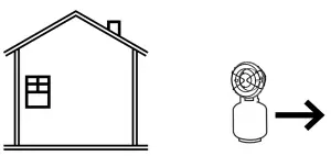 |
WARNING marking concerning Risk of Respiratory Injury. Do not use this heater for heating human living quarters. |
 |
WARNING marking concerning Risk of Fire while handling propane. Do not smoke while handling gas. |
IMPORTANT SAFETY INFORMATION

Improper assembly, installation, adjustment, alteration, service, use, or maintenance can cause property damage, PERSONAL INJURY, or DEATH.
Read all safety warnings and all instructions.
Failure to follow the warnings and instructions may result in electric shock, fire and/or serious injury.
The warnings, precautions, and instructions discussed in this instruction manual cannot cover all possible conditions and situations that may occur. It must be understood by the operator that common sense and caution are factors which cannot be built into this product, but must be supplied by the operator.
Save all warnings and instructions for future reference.
Leaking Propane Gas
- If you smell gas:
a. Shut off gas to the Heater.
b. Extinguish any open flame.
c. Do not light a match or operate an electrical switch.
d. Evacuate the area at once.
e. Call for professional help. - Propane gas is a gas you cannot see or smell. Propane gas normally has an odorant added to aid detection. The odorant smells like “rotten eggs“. The odorant may fade over time, so leaking gas may not be detectable by smell alone.
- Propane gas is heavier than air and will collect in low areas.
Risk of Fire and/or Explosion
- Do not store extra propane tanks near the Heater.
- If gas is smelled during operation, immediately close the valve on the propane tank. Propane gas is odorless. An odor-making agent is added to propane/LP gas to enable you to smell the gas if it may be leaking.
- If the Heater shuts off during operation, close the valve on the propane tank. Check the amount of gas in the tank and wait 5 minutes for the gas to clear before restarting. If it continues to shut off during operation, have it serviced by a qualified technician.
- Do not use the Heater within 15 feet of flammable objects such as wood, trees, overhangs, and umbrellas.
- Do not store propane near high heat, open flames, pilot lights, direct sunlight, other ignition sources or where temperatures exceed 120°F.
- Do not use in spaces which may contain volatile or airborne combustibles, or products such as gasoline, solvents, paint thinner, dust particles or unknown chemicals.
- Operate with the propane tank in its vertical upright position, on a non-combustible surface. While in operation, do not tilt or lean the propane tank on its side. Do not turn the tank upside down, not even when it seems empty, as this may cause clogging of valves and components which could lead to dangerous flare-ups or fire.
- Do not install or remove the Propane tank while the Heater is lighted, near flames, pilot lights or other ignition sources or while the Heater is hot. Only do this in an outdoor, well-ventilated area.
- Position and operate Heater so that it is not exposed to water spray, rain, or dripping water.
- Remove all packing materials before using this product.
- Clothing or other flammable materials should not be hung from the Heater or placed on or near the Heater.
- Do not use below ground level.
- Read instructions provided with propane tank before connection or use.
Carbon Monoxide Hazard
Burning propane indoors CAN KILL YOU IN MINUTES.
Exhaust from propane-fueled equipment contains carbon monoxide.
This is a poison you cannot see or smell.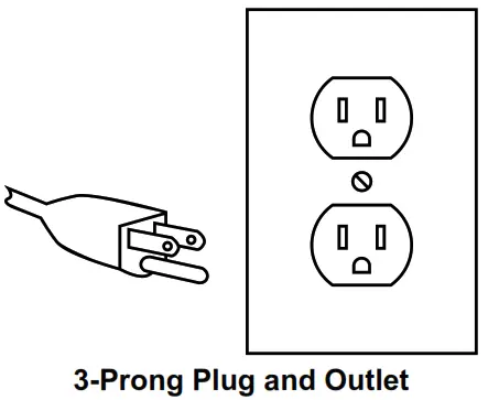
NEVER use inside a home, tent, camper, or garage, EVEN IF doors and windows are open.

Only use OUTSIDE and far away from windows, doors, and vents.
Early signs of carbon monoxide poisoning resemble the flu, with headaches, dizziness, or nausea.
If you have these signs, this item may not be working properly.
Get fresh air immediately.
DO NOT USE THIS ITEM FOR SPACE HEATING.
Risk of Burns – Product Gets Very Hot During Use
- Do not attempt to move the Heater while it is in operation. Turn it off and wait 30 minutes until it cools down before moving.
- Do not touch the burner or any other metal components while the Heater is lit. Before servicing, wait 30 minutes for it to cool down.
- Keep children away from the Heater.
Operation Precautions
- USE ONLY ON LEVEL, STABLE, FIREPROOF SURFACE OUT OF REACH OF CHILDREN.
- Inspect before each use; do not use if parts loose, leaking, or damaged. Connect, then check for leaks using soapy water. Do not use flame to check for leaks. Only qualified technician may repair product.
- Close Heater Regulator Knob before connection.
- Close Heater Regulator Knob after use and before leaving area. Do not leave unattended while lit.
- Set up and use according to manual instructions only.
- Wear ANSI-approved safety goggles with side shields during connection and lighting.
- This Heater must be used only with HD-5 propane gas. The propane tank should hold no more than 20 pounds of LP gas. Do not use bulk tanks of larger capacity. Do not use any other fuel. The Heater must be used only with a vapor withdrawal LP propane tank equipped with a POL valve. The tank must be constructed and marked in such a way as to comply with the specifications for LP gas tanks by the U.S. Department of Transportation (DOT).
- The use of this product must be in conformity with local codes or, in the absence of local codes, with the standard for storage and Handling of Liquefied Petroleum Gases, ANSI/NFPA 58.
- People with pacemakers should consult their physician(s) before use. Electromagnetic fields in close proximity to heart pacemaker could cause pacemaker interference or pacemaker failure.
- Keep children away. Children must never be allowed in the work area. Do not let them handle, move, or adjust this product.
- Store idle equipment. When not in use, this product must be stored in a dry location to inhibit rust. Lock up Heater and keep out of reach of children.
- Use as intended only. Do not alter product in any way, or use with any accessory not specifically designed for this product.
- Maintain product labels and nameplates. These carry important safety information. If unreadable or missing, contact Harbor Freight Tools for a replacement.
![]() WARNING
WARNING
Air Quality Hazard
- Do not use this heater for heating human living quarters.
- Use of direct-fired heaters in the construction environment can result in exposure to levels of CO, CO2, and NO2 considered to be hazardous to health and potentially life threatening.
- Do not use in unventilated areas
- Know the signs of CO and CO2 poisoning
- Headaches, stinging eyes
- Dizziness, disorientation
- Difficulty breathing, feels of being suffocated
- Proper ventilation air exchange (OSHA 29 CFR 1926.57) to support combustion and maintain acceptable air quality shall be provided in accordance with OSHA 29 CFR Part 1926.154, ANSI A10.10 Safety Requirements for Temporary and Portable Space Heating Devices and Equipment used in the Construction Industry or the Natural Gas and Propane Installation Codes CSA B149.1
- Periodically monitor levels of CO, CO2 and NO2 existing at the construction site – at the minimum at the start of the shift and after 4 hours.
- Provide ventilation air exchange, either natural or mechanical, as required to maintain acceptable indoor air quality
| USA 8-Hr Time weighted average (OSHA 29 CFR 1926.55 App A) |
Canada 8-hr time weighted average WorkSafe BC OHS Guidelines Part 5.1 and Ontario Workplaces Reg 833 | |
| CO | 50 ppm | 25 ppm |
| CO2 | 5000 ppm | 5000 ppm |
| NO2 | 3 ppm (Reg 833) | |
| USA – Ceiling Limit (Short Term Exposure Limit = 15 minutes) |
Canada STEL (15 minutes Reg 833/1 hour WSBC) WorkSafe BC OHS Guidelines Part 5.1 and Ontario Workplaces Reg 833 |
|
| CO | 100 ppm | |
| CO2 | 15000 ppm (WSBC) 30000 ppm (Reg 833) |
|
| NO2 | 5 ppm | 1.0 ppm (WorkSafeBC) 5.0 ppm (Reg 833) |
• Ensure that the flow of combustion and ventilation air exchange cannot become obstructed.
• As the building ‘tightens up’ during the construction phases ventilation may need to be increased.
![]() SAVE THESE INSTRUCTIONS.
SAVE THESE INSTRUCTIONS.
Grounded Tools: Tools with Three Prong Plugs
- Tools marked with “Grounding Required” have a three wire cord and three prong grounding plug. The plug must be connected to a properly grounded outlet. If the tool should electrically malfunction or break down, grounding provides a low resistance path to carry electricity away from the user, reducing the risk of electric shock. (See 3-Prong Plug and Outlet.)
- The grounding prong in the plug is connected through the green wire inside the cord to the grounding system in the tool. The green wire in the cord must be the only wire connected to the tool’s grounding system and must never be attached to an electrically “live” terminal. (See 3-Prong Plug and Outlet.)
- The tool must be plugged into an appropriate outlet, properly installed and grounded in accordance with all codes and ordinances. The plug and outlet should look like those in the preceding illustration. (See 3-Prong Plug and Outlet.)
Extension Cords
- Grounded tools require a three wire extension cord. Double Insulated tools can use either a two or three wire extension cord.
- As the distance from the supply outlet increases, you must use a heavier gauge extension cord. Using extension cords with inadequately sized wire causes a serious drop in voltage, resulting in loss of power and possible tool damage. (See Table A.)
- The smaller the gauge number of the wire, the greater the capacity of the cord. For example, a 14 gauge cord can carry a higher current than a 16 gauge cord. (See Table A.)
- When using more than one extension cord to make up the total length, make sure each cord contains at least the minimum wire size required. (See Table A.)
- If you are using one extension cord for more than one tool, add the nameplate amperes and use the sum to determine the required minimum cord size. (See Table A.)
- If you are using an extension cord outdoors, make sure it is marked with the suffix “W-A” (“W” in Canada) to indicate it is acceptable for outdoor use.
- Make sure the extension cord is properly wired and in good electrical condition. Always replace a damaged extension cord or have it repaired by a qualified electrician before using it.
- Protect the extension cords from sharp objects, excessive heat, and damp or wet areas.
| TABLE A: RECOMMENDED MINIMUM WIRE GAUGE FOR EXTENSION CORDS* (120/240 VOLT) | |||||
| NAMEPLATE AMPERES (at full load) |
EXTENSION CORD LENGTH | ||||
| 25′ | 50′ | 75′ | 100′ | 150′ | |
| 0 — 2.0 | 18 | 18 | 18 | 18 | 16 |
| 2.1 — 3.4 | 18 | 18 | 18 | 16 | 14 |
| 3.5 — 5.0 | 18 | 18 | 16 | 14 | 12 |
| 5.1 — 7.0 | 18 | 16 | 14 | 12 | 12 |
| 7.1 — 12.0 | 18 | 14 | 12 | 10 | – |
| 12.1 — 16.0 | 14 | 12 | 10 | – | |
| 16.1 — 20.0 | 12 | 10 | – | ||
| * Based on limiting the line voltage drop to five volts at 150% of the rated amperes. | |||||
Symbology
| V | Volts |
| ∼ | Alternating Current |
| A | Amperes |
 |
WARNING marking concerning Risk of Fire. Do not cover ventilation ducts. Keep flammable objects away. |
| WARNING marking concerning Risk of Electric Shock. Properly connect power cord to appropriate outlet. |
Specifications
| Input Rating | 39,000 – 64,000 btu/h |
| Manifold Pressure | 10 PSIG/277 inch w.c./0.69 bar |
| Minimum Ambient Temperature Rating |
14º F (-10º C) |
| Gas Type | Propane |
| Gas Supply Pressure | 25 – 250 PSI |

Setup – Before Use
![]() Read the ENTIRE IMPORTANT SAFETY INFORMATION section at the beginning of this manual including all text under subheadings therein before set up or use of this product.
Read the ENTIRE IMPORTANT SAFETY INFORMATION section at the beginning of this manual including all text under subheadings therein before set up or use of this product.
Note: For additional information regarding the parts listed in the following pages, refer to the Assembly Diagram near the end of this manual.
Components and Controls

Operation Instructions
![]() Read the ENTIRE IMPORTANT SAFETY INFORMATION section at the beginning of this document including all text under subheadings therein before set up or use of this product.
Read the ENTIRE IMPORTANT SAFETY INFORMATION section at the beginning of this document including all text under subheadings therein before set up or use of this product.
![]() WARNING
WARNING
TO PREVENT SERIOUS INJURY AND DEATH FROM FIRE:
Have multiple ABC class fire extinguishers nearby. Be familiar with fire extinguishing techniques before use of this item. Heater must be located at least 6′ away from any propane gas container. Heater must not be directed toward any propane-gas container within 20′.
Setup
- Locate the propane tank (not included) behind the Heater and at lease 6′ away from the Heateron the ground. Keep the Heater and propane tank away from flammable objects. Make sure the Heater and propane tank are level and stable.
- Adjust Height by loosening Height Adjustment Knob, moving it up or down, then tightening Knob.
Connect
- Close gas valve on propane tank. Connect Hose to propane tank.
- Close Gas Knob on Heater. Connect Hose to Heater.
- Hand tighten the fittings.
- Using the wrench supplied with the heater, tighten up to a quarter turn from hand tight on the flare fitting connections between the hose and heater gas inlet and the hose and the propane tank. Do not overtighten.
- Open gas valve on propane tank and check and smell for gas leaks. Perform a leak test:
a. Apply warm soapy water over every joint, regulator, fitting, and anywhere else there may be a possible leak.
b. Observe carefully to see if bubbles expand, indicating a leak. A large leak can blow the soapy solution away instead of forming bubbles.
c. If leaks are found, do not use the Heater until the leaks have been stopped.
d. Hand tighten the fittings.
e. Using the wrench supplied with the heater, tighten up to a quarter turn from hand tight on the flare fitting connections between the hose and heater gas inlet and the hose and the propane tank. Do not overtighten.
f. Repeat the soapy water leak test to confirm the fittings are tightened properly.
g. After testing, close gas valve on the propane tank and close Gas Knob on Heater.
Start/Stop
- Plug Power Cord into grounded 120VAC outlet.
- Turn Power Switch on. Let fan run for 30 seconds.
- Slowly open gas valve on propane tank, then open Gas Knob on Heater a quarter turn.
- Start Heater:
WARNING! TO PREVENT SERIOUS INJURY: Do not stand in front of Heater while lighting Burner.
WARNING! TO PREVENT SERIOUS INJURY: If Burner does not light within 30 seconds: Close Gas Knob on Heater. Allow at least five minutes for gas to dissipate, then repeat the lighting process.
a. Position yourself behind heater.
b. Push and hold Gas Valve on left side.
c. Push and hold Ignition Button on right side until Burner lights.
d. Release Ignition Button, hold Gas Valve for 5 seconds.
e. Release Gas Valve. - Adjust Gas Knob as necessary.
- Stop Heater:
a. Close gas valve on propane tank.
b. Close Gas Knob on Heater.
c. Let fan run for 2 minutes.
d. Turn Power Switch off and unplug Heater.
e. Disconnect Hose from Heater and propane tank. - Store Heater according to Inspection, Maintenance, and Cleaning on page 12.
WARNING! TO PREVENT SERIOUS INJURY: Do not move the Heater while it is on or while it is hot. Do not touch the Burner Assembly or other metal components—serious burns will occur. Turn unit off and wait 30 minutes until it cools down before moving.
Inspection, Maintenance, and Cleaning
![]() Procedures not specifically explained in this manual must be performed only by a qualified technician.
Procedures not specifically explained in this manual must be performed only by a qualified technician.
Any guard or other protective device removed for servicing must be replaced before operation.
![]() WARNING
WARNING
TO PREVENT SERIOUS INJURY FROM ACCIDENTAL OPERATION:
Close the valve on the propane tank, allow the product to cool for at least 30 minutes, and disconnect the propane tank before performing any procedure in this section.
TO PREVENT SERIOUS INJURY FROM TOOL FAILURE:
Do not use damaged equipment. If abnormal noise or vibration occurs, have the problem corrected before further use.
- BEFORE EACH USE, inspect the general condition of the product. Check for:
• check all gas fittings for tightness
• damage to hose. If hose has excessive abrasion or wear, or the hose is cut, it shall be replace prior to the heater being put into operation.
• loose hardware
• misalignment or binding of moving parts
• cracked or broken parts
• any other condition that may affect its safe operation
• do a leak test using soapy water – refer to Connect on page 11 . - AFTER USE, wipe external surfaces of the tool with clean cloth.
- ONCE A YEAR, have Heater inspected by qualified technician.
- STORE the Heater in a safe, dry place, covered to protect it from dust and dirt and out of reach of children. If storing indoors, first shut off and remove the propane tank and store in an area where there is free air circulation, at least 10 ft from building openings (such as windows and doors), and at least 20 ft from air intakes of air conditioning and ventilating systems. Tightly install threaded valve plug (not included) into disconnected propane tank.
Do not store in spaces which may contain volatile or airborne combustibles, or products such as gasoline, solvents, paint thinner, dust particles or unknown chemicals.
PLEASE READ THE FOLLOWING CAREFULLY
THE MANUFACTURER AND/OR DISTRIBUTOR HAS PROVIDED THE PARTS LIST AND ASSEMBLY DIAGRAM IN THIS DOCUMENT AS A REFERENCE TOOL ONLY. NEITHER THE MANUFACTURER OR DISTRIBUTOR MAKES ANY REPRESENTATION OR WARRANTY OF ANY KIND TO THE BUYER THAT HE OR SHE IS QUALIFIED TO MAKE ANY REPAIRS TO THE PRODUCT, OR THAT HE OR SHE IS QUALIFIED TO REPLACE ANY PARTS OF THE PRODUCT. IN FACT, THE MANUFACTURER AND/OR DISTRIBUTOR EXPRESSLY STATES THAT ALL REPAIRS AND PARTS REPLACEMENTS SHOULD BE UNDERTAKEN BY CERTIFIED AND LICENSED TECHNICIANS, AND NOT BY THE BUYER. THE BUYER ASSUMES ALL RISK AND LIABILITY ARISING OUT OF HIS OR HER REPAIRS TO THE ORIGINAL PRODUCT OR REPLACEMENT PARTS THERETO, OR ARISING OUT OF HIS OR HER INSTALLATION OF REPLACEMENT PARTS THERETO.
Parts List and Diagram
| Part | Description | Qty | Part | Description | Qty |
| 1 | Inlet Grill | 1 | 12-7 | Joint | 1 |
| 2 | Motor Assembly | 1 | 12-8 | Elbow 1 | 1 |
| 3 | Fan | 1 | 12-9 | Elbow 2 | 1 |
| 4 | Main Housing | 1 | 12-10 | Nozzle | 1 |
| 5 | Handle | 1 | 12-11 | Adjustment Nut | 1 |
| 6 | Combustion Housing | 1 | 13 | Burner | 1 |
| 7 | Power Cord | 1 | 14 | Igniting Electrode | 1 |
| 8 | Power Cord Fastener | 1 | 15 | Thermostat | 1 |
| 9 | Power Cord Cable Clip | 1 | 16 | Front Panel | 1 |
| 10 | Cover | 1 | 17 | Knob | 1 |
| 11 | Thermo Element | 1 | 18 | Rear Panel | 1 |
| 12 | Safety Valve Assembly | 1 | 19 | Bracket | 1 |
| 12-1 | Nut | 1 | 20 | Pulse Igniter | 1 |
| 12-2 | Safety Valve | 1 | 21 | Screw | 2 |
| 12-3 | Solenoid Valve | 1 | 22 | Ignition Button | 1 |
| 12-4 | Knob | 1 | 23 | Power Switch | 1 |
| 12-5 | Nut | 2 | 24 | Base | 1 |
| 12-6 | Control Valve | 1 |

Record Serial Number Here:
Note: If product has no serial number, record month and year of purchase instead.
Note: Some parts are listed and shown for illustration purposes only, and are not available individually as replacement parts.
Limited 90 Day Warranty
Harbor Freight Tools Co. makes every effort to assure that its products meet high quality and durability standards, and warrants to the original purchaser that this product is free from defects in materials and workmanship for the period of 90 days from the date of purchase. This warranty does not apply to damage due directly or indirectly, to misuse, abuse, negligence or accidents, repairs or alterations outside our facilities, criminal activity, improper installation, normal wear and tear, or to lack of maintenance. We shall in no event be liable for death, injuries to persons or property, or for incidental, contingent, special or consequential damages arising from the use of our product. Some states do not allow the exclusion or limitation of incidental or consequential damages, so the above limitation of exclusion may not apply to you. THIS WARRANTY IS EXPRESSLY IN LIEU OF ALL OTHER WARRANTIES, EXPRESS OR IMPLIED, INCLUDING THE WARRANTIES OF MERCHANTABILITY AND FITNESS.
To take advantage of this warranty, the product or part must be returned to us with transportation charges prepaid. Proof of purchase date and an explanation of the complaint must accompany the merchandise. If our inspection verifies the defect, we will either repair or replace the product at our election or we may elect to refund the purchase price if we cannot readily and quickly provide you with a replacement. We will return repaired products at our expense, but if we determine there is no defect, or that the defect resulted from causes not within the scope of our warranty, then you must bear the cost of returning the product. This warranty gives you specific legal rights and you may also have other rights which vary from state to state.
26541 Agoura Road • Calabasas, CA 91302 • 1-888-866-5797
]]>