Honeywell Home TH6220WF2006 PRO T6 Smart Programmable Thermostat

Honeywell Home TH6220WF2006 PRO T6 Smart Programmable Thermostat
Package Includes
- T6 Pro Smart Thermostat
- UWPTM Mounting System
- Decorative Cover Plate
- Screws and anchors
- Thermostat literature
Search for local rebates: HoneywellHome.com/Rebates
Read before installing Compatibility
- Compatible with most heating, cooling, and heat pump systems
- Required: 24 VAC power (“C” wire)
- Input: 24 V ~ @ 60 Hz, 1 A
- Does not work with electric baseboard heat (120V-240V)
- Android or iOS smartphone or tablet
Customer assistance
WEB customer.resideo.com
PHONE: 1-800-633-3991

Optional Decorative Cover Plate installation
NOTE: If the Optional Cover Plate is not required, see “UWP Mounting System installation” on the next page.
Use the Optional Cover Plate when you need to cover the paint gap from old thermostat.
There are different cover plates depending on when the thermostat was manufactured.
For the square cover plate: 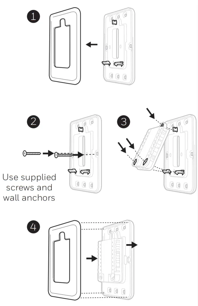
- Separate the Cover Plate from Mounting Plate.
- Mount the Mounting Plate onto the wall using any of the 8 screw holes. Insert and tighten mounting screws supplied with Cover Plate Kit. Do not overtighten. See Figure
- Make sure the Mounting Plate is level.
- Attach the UWP by hanging it on the top hook of the Mounting Plate and then snapping the bottom of the UWP in place. See Figure 3.
- Snap the Cover Plate onto the Mounting Plate. See Figure 4.
For the rectangular cover plate:
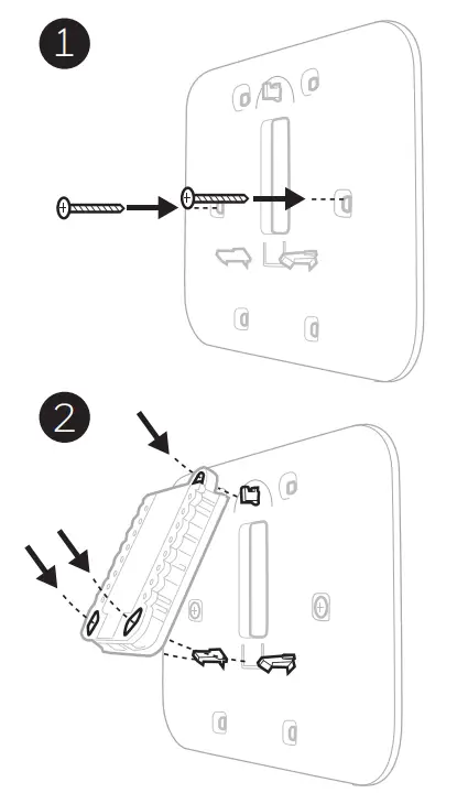
1. Mount the Cover Plate on the wall using any of the 6 screw holes. Insert and tighten the mounting screws supplied with the Cover Plate. Do not overtighten. See Figure
- Make sure the Cover Plate is level. Attach the UWP by hanging it on the top hook of the Cover Plate and then snapping the bottom of the UWP in place. See Figure 2.
- If there are no existing wall anchors:
 a. Position the Cover Plate on wall. Level and mark hole positions. See Figure 1.
b. Drill holes at marked positions, and then lightly tap supplied wall anchors into the wall using a hammer.
- If your box contains red anchors, drill 7/32″ (5.6 mm) holes.
- If your box contains yellow anchors, drill 3/16″ (4.8 mm) holes.
- Use 2x supplied screws (#8 1-1/2″ (38 mm) for red anchors and #6 1-1/2″ (38 mm) for yellow anchors).
UWP Mounting System installation
- Open the package to find the UWP.
- Position the UWP on the wall. Level and mark hole positions. See Figure 2.
Drill holes at marked positions, and then lightly tap supplied wall anchors into wall using a hammer.
If your box contains red anchors, drill 7/32″ (5.6 mm) holes for drywall.
If your box contains yellow anchors, drill 3/16″ (4.8 mm) holes for drywall. - Pull the door open and insert wires through the wiring hole of the UWP. See Figure 3.
- Place the UWP over the wall anchors. Insert and tighten mounting screws supplied with the UWP. Do not overtighten. Tighten until the UWP no longer moves. Close the door. See Figure 4.
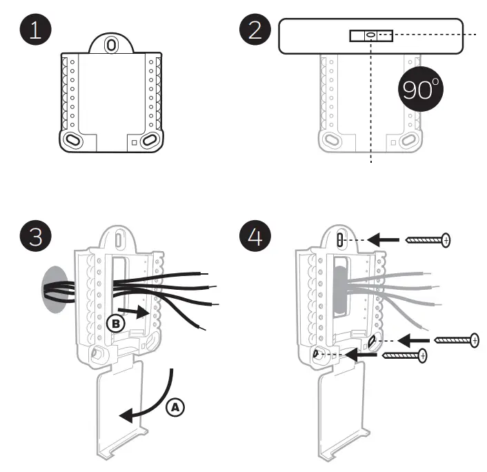
Use 3x supplied screws (#8 1-1/2″ [38 mm] for red anchors and #6 1-1/2 [38 mm] for yellow anchors)
Wiring UWP
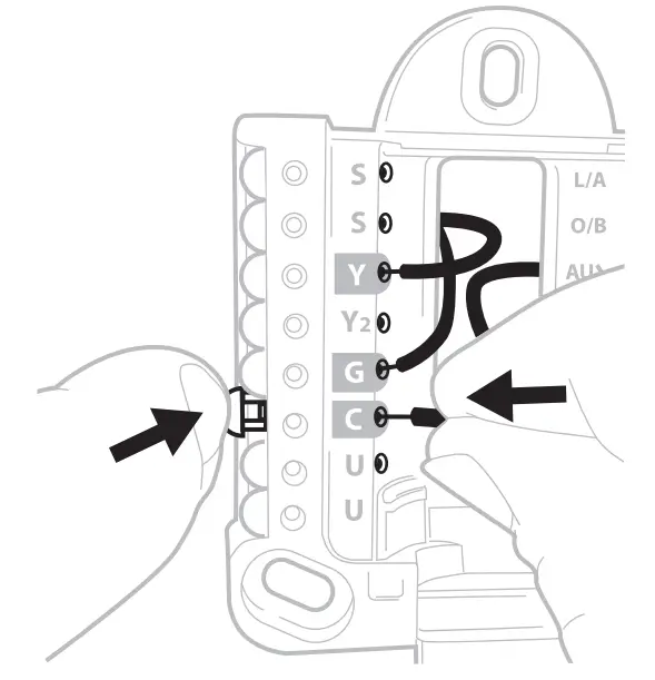
Push down on the tabs to put the wires into the inner holes of their corresponding terminals on the UWP (one wire per terminal) until they are firmly in place. Gently tug on the wires to verify they are secure. If you need to release the wires again, push down the terminal tabs on the sides of the UWP.
 This wiring is just an example, yours may vary.
Terminal designations
| Conventional Systems | Heat pump systems | ||
| Terminal | Description | Terminal | Description |
| S/S | Input for a wired indoor, outdoor sensor | S/S | Input for a wired indoor, outdoor sensor |
| Y | Compressor Stage 1 | Y | Compressor Stage 1 |
| Y2 | Compressor Stage 2 | Y2 | Compressor Stage 2 |
| G | Fan Relay | G | Fan Relay |
| C | 24VAC Common wire from the secondary side of the cooling transformer (if 2 transformers) | C | 24VAC Common wire from the secondary side of the cooling transformer |
| K* | Connect to K on the C-wire adaptor | K* | Connect to K on the C-wire adaptor |
| U/U** | Relay for ventilation | U/U** | Relay for ventilation |
| A | L/A | Connect to compressor monitor | |
| W | Heat Stage 1 | O/B | Changeover valve for heat pumps |
| W2 | Heat Stage 2 | Aux | Backup Heat |
| E | Emergency Heat | ||
| R | 24 VAC Heating transformer | R | 24 VAC Heating transformer |
| Rc | 24 VAC Cooling transformer | Rc | 24 VAC Cooling transformer |
* The THP9045A1098 C-wire adaptor is used on heat/cool systems when you only have four wires at the thermostat and you need a fifth wire for a common wire. Use the K terminal in place of the Y and G terminals on conventional or heat pump systems to provide control of the fan and the compressor through a single wire–the unused wire then becomes your common wire. See THP9045 instructions for more information.
** Ventilation is not available on all models. When the U slider is in the down position (2 wires), the U contacts are a dry set of contacts. If your ventilation system requires 24 volts, move the U slider to the up position (1 wire). The lower U terminal is internally jumped to the Rc terminal. In this application, you would hook up one wire from your damper to the upper U terminal and the other to the common side of the transformer.
Setting Slider Tabs
Set R Slider Tab, see Figure 1.
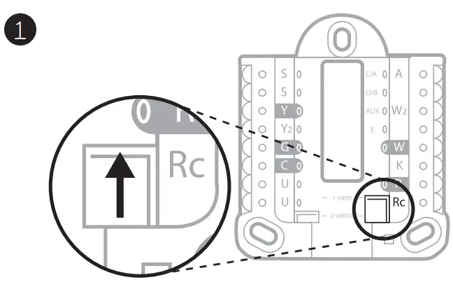
- Use a built-in jumper (R Slider Tab) to differentiate between one or two transformer systems.
- If there is only one R wire, and it is connected to the R, Rc, or RH terminal on the old thermostat, set the slider to the up position (1 wire).
- If there is one wire connected to the R terminal and one wire connected to the Rc terminal, set the slider to the down position (2 wires).
Set U Slider Tab, see Figure 2.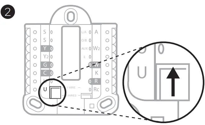
- Use a built-in jumper (U Slider Tab) of the relay to wire ventilation. Please note that ventilation is not supported on all models.
- When the U Slider Tab is in the down position (2 wires) the U contacts are a dry set of contacts.
- If the ventilator is powered by the cooling transformer, move the jumper switch to the up position (1 wire). With this switch set to 1 wire, the lower U terminal is internally jumped to the Rc terminal. In this application, hook up one wire from the vent damper to the U terminal and the other to the common side of the cooling system transformer.
Wiring
NOTES:
- Available wiring configurations differ by product models/product numbers.
- Use 18- to 22- gauge thermostat wire. A shielded cable is not required.
- Set the R Slider Tab on the UWP to the up position (1 wire) for 1 transformer system or the down position (2 wires) for 2 transformer systems. See “Setting Slider Tabs” on page 5.
- Set the U Slider Tab to the up position (1 wire) for non-powered ventilation or the down position (2 wires) for powered ventilation. See “Setting Slider Tabs” on page 5.
Conventional systems
| 1H/1C System (1 transformer) R Power Rc [R+Rc joined by Slider Tab] Y C Kompressor contactor C 24V A common W Heat the relay G Fan relay |
Hot Water Relay Panel R Power Rc [R+Rc joined by Slider Tab] W Heat Relay C 24VAC common NOTE: If the panel does not provide 24 volts of AC at R and C, set the slider to a down position and wire a separate transformer to Rc and C. |
| 1H/1C System (2 transformers) R Power (heating transformer) Rc Power (cooling transformer) Y Compressor contactor C 24 VAC common from the cooling transformer W Heat relay G Fan relay |
Heat-only System with Fan R Power Rc [R+Rc joined by Slider Tab] C 24VAC common W Heat relay G Fan relay |
| 2H/2C System (1 transformer) R Power Rc [R+Rc joined by Slider Tab] Y Compressor contactor (stage 1) C 24VAC common W Heat the relay (stage 1) G Fan relay W2 Heat the relay (stage 2) Y2 Compressor contactor (stage 2) |
Cool-only System with Fan R Power Rc [R+Rc joined by Slider Tab] Y Compressor contactor C 24VAC common G Fan relay |
| 1H/1C Heat Pump System R Power Rc [R+Rc joined by Slider Tab] Y Compressor contactor C 24VAC common O/B Changeover valve G Fan relay |
2H/2C Heat Pump System R Power Rc [R+Rc joined by Slider Tab] Y Compressor contactor (stage 1) C 24VAC common O/B Changeover valve G Fan relay Y2 Compressor contactor (stage 2) L Heat pump fault input |
| 2H/1C Heat Pump System R Power Rc [R+Rc joined by Slider Tab] Y Compressor contactor C 24VAC common O/B Changeover valve G Fan relay Aux Auxiliary heat* E Emergency heat relay* L Heat pump fault input NOTE: If dual fuel, TH6320WF2003 model needed. |
3H/2C Heat Pump System R Power Rc [R+Rc joined by Slider Tab] Y Compressor contactor (stage 1) C 24VAC common O/B Changeover valve G Fan relay Aux Auxiliary heat* E Emergency heat relay* Y2 Compressor contactor (stage 2) L Heat pump fault input NOTE: TH6320WF2003 only. |
NOTE: Do NOT use W for heat pump applications. Auxiliary heat must wire to AUX or E.
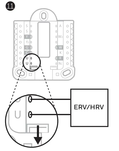
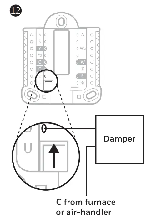
* If you do not have separate wires for the Aux and E terminals, connect the wire to the Aux terminal. 7Ventilation systems
NOTE: Ventilation is not available on all models.
Using U Slider Tab
Wired to ERV/HRV whole house ventilator with internal power supply.
 Wired to fresh air damper powered by furnace transformer.
Mounting thermostat
- Push excess wire back into the wall opening.
- Close the UWP door. It should remain closed without bulging.
- Align the UWP with the thermostat, and push gently until the thermostat snaps in place.
- If needed, gently pull to remove the thermostat from the UWP.
- Search for local rebates: Your thermostat may now be eligible for local rebates. Search for offers in your area at HoneywellHome.com/Rebates
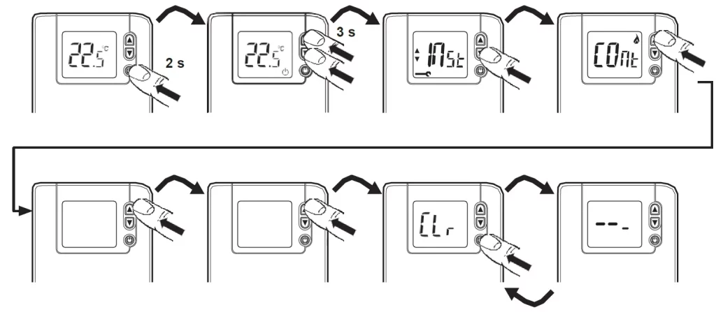
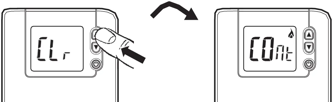
Installer setup- using the thermostat
Setup using the thermostat
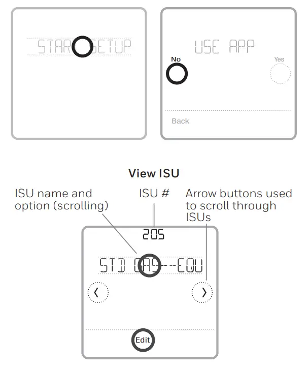
- After the thermostat has powered up, touch START SETUP on the thermostat. You’ll be asked if you want to perform setup via the app. Touch No.
- Touch < or > toggle between Installer Set-Up (ISU) options.
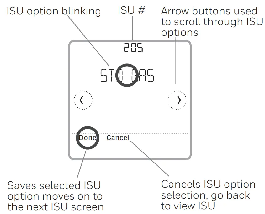
- Touch Edit < or > touch the text area and then touch or edit the default setup option.
- Touch Done < or > touch the text area to confirm the setting or press Cancel.
- Touch < or > to continue to set up another ISU option.
NOTES:
- To see a list of all setup parameters, go to “Installer setup options (ISU) advanced menu” on page 12. The thermostat displays the ISU name and the ISU number.
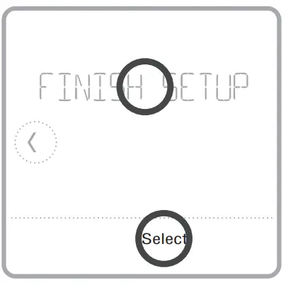
- To finish setup and save your settings, scroll to the Finish screen at the end of the ISU list.
- Touch Select or touch text area to save changes and exit, or touch to return to initial setup screen.
Installer setup using the Resideo Pro app
Setup using the app
Download the Resideo Pro or Honeywell Home app from App Store or Google Play to install and personally invite your customer to connect the installed thermostat at the same time.![]()
With the Resideo Pro app, you can personally invite your customer to connect their account.
Installer setup advanced menu
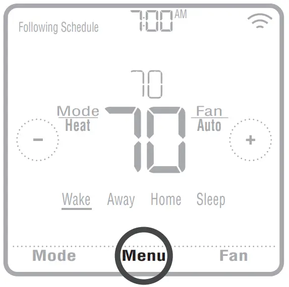
To access the advanced menu, press and hold the Menu button for 5 seconds. Touch or to go through the options in the advanced menu.
 Advanced menu options
Device Setup
This is used to access the device ISU setting.
Screen Lock
The thermostat touch screen can be set to lock fully or partially.
Rater View
A read-only place to view all the ventilation settings.
System Test
Test the heating and cooling system.
Range Stop (Temperature)
Set the minimum, maximum, cool and heat temperature set points.
Reset
Access all reset options on the thermostat.
This is the only place to access factory reset.
Key features
Note: Long press of Menu button for 5 seconds to access Advanced Menu options.
The screen will wake up by pressing the center area of the displayed temperature. The screen will stay lit for 45 seconds. Brightness can be adjusted in the Menu.
Installer setup options (ISU) advanced menu
Table 1.
Note: ISU options available may vary upon the thermostat model and equipment setup.
| # ISU | ISU Name | ISU Options (defaults in bold) | Notes |
| 120 | Schedule Type | No Schedule MO-SU = Every day the same MO-FR, SA, SU = 5-1-1 scheduleMO-FR, SA-SU = 5-2 schedule Each Day = Everyday individual | You can change the default MO-FR, and SA-SU schedule here. To edit periods during days, temperature setpoints, or to turn Schedule On/Off, from the home screen, go to MENU/SCHEDULE. |
| 125 | Temp Scale | Fahrenheit, Celsius | |
| 130 | Outdoor Temp | No, Wired, Internet | Select outdoor temperature data source. This ISU automatically defaults to the Internet when registered to the Honeywell Home app and no wired outdoor sensor is selected. We recommend using a wired outdoor sensor connected to the “S” terminals on the UWP. (See “Wiring” on page 6.) An outdoor temperature is required to set the following ISUs: ISU 355 Compressor Lockout, ISU 356 Aux Heat Lockout, ISU 1013 Low Outdoor Temperature Ventilation Lockout, ISU 1014 High Outdoor Temperature Ventilation Lockout, and ISU 1015 High Outdoor Dew Point Ventilation Lockout. |
| 200 | System Type | Conventional Forced Air Heat Pump Boiler Cool Only |
A basic selection of systems your thermostat will control. |
| 205 | Equipment Type | Conventional Forced Air Heat: Standard Gas (STD GAS), High Efficiency Gas (EFF GAS), Oil, Electric, Fan Coil* Heat Pump: Air To Air, Geothermal Boiler: Hot Water, Steam |
This option selects the equipment type your thermostat will control. Note: This option is NOT displayed if ISU 200 is set to Cool Only. *Fan coil setting is for a residential application with a hot water coil in an air-handler. |
| 218 | Reversing Valve | 0/B on Cool, 0/B on Heat | This ISU is only displayed if ISU 200 is set to Heat Pump. Select whether reversing valve O/B should energize on cool or on heat |
| 220 | Cool Stages (#200=Conv./ 200=HP) | 0, 1, 2 | Only 1 compressor stage is available on the TH6220WF model if configured for a heat pump. |
| 221 | Heat Stages/Aux/E Stages (#200=Conv./ 200=HP) | Heat Stages: 0, 1, 2
AUX/E Stages: 0, 1 |
Maximum of 2 Heat Stages for conventional systems. Maximum of 1 Aux/E stage for heat pump systems. |
| 230 | Fan Control | Equipment, Thermostat | This ISU is only displayed if ISU 205 is set to Electric Forced Air or Fan Coil. |
| 253 | Aux/E Control | Both Aux/E, Either Aux/E | Set “EITHER AUX/E” if you want to set up and control Auxiliary and Emergency heating separately. This ISU is only displayed if ISU 200 is set to Heat Pump AND if ISU 221 Aux/E stages = 1. Note: This ISU is available on the TH6320 model only. |
| # ISU | ISU Name | ISU Options (defaults in bold) | Notes |
| 255 | Aux Heat Type | Electric, Gas/Oil (or Fossil Forced Air) | This ISU is displayed only if ISU 200 is set to heat pump AND if ISU 221 Aux/E heat stages = 1. Note: Options of this ISU may vary depending on the model of the thermostat. |
| 256 | EM Heat Type | Electric, Gas/Oil (or Fossil Forced Air) | This ISU is displayed only if ISU 200 is set to Heat Pump AND if ISU 221 Aux/E heat stages = 1 AND if ISU 253 is set to run AUX/E heat separately.
Note: This ISU may not be available at all on some models. |
| 260 | Fossil Kit Control | Thermostat, External (Fossil Fuel Kit Controls Backup Heat) | This ISU is displayed only if ISU 200 is set to Heat Pump AND if ISU 221 Aux/E heat stages = 1, AND if ISU 256 is set to Gas/Oil. Note: This ISU is available on the TH6320 model only. |
| 300 | Auto Changeover | On, Off | OFF: The user must select heating or cooling as needed to maintain the desired indoor temperature. ON (Automatic): On (enabled) Allows the user to select Auto Changeover as one of the system modes from the home screen. In auto mode, the thermostat can control either heating or cooling to maintain the desired indoor temperature. |
| 303 | Auto Differential | 0 °F to 5 °F or 0.0 °C to 2.5 °C | The differential is the minimum number of degrees rise or fall required during off-cycle to switch from the last active mode (heat or cool) to the opposite mode when the thermostat is in auto-changeover. The differential is NOT deadband. The deadband temperature between when heating (or cooling) cycles on and cycles off to maintain the setpoint is not adjustable. The thermostat uses an algorithm that fixes Deadband at 0 °F (0 ° C). |
| 305 | High Cool Stage Finish | Yes, No | This ISU is only displayed when the thermostat is set to 2 cool stages. When set to YES, this feature keeps the higher stage of the cooling equipment running until the desired setpoint is reached. |
| 306 | High Heat Stage Finish | Yes, No | This ISU is only displayed when the thermostat is set to 2 or more heat stages. When set to YES, this feature keeps the higher stage of the heating equipment running until the desired setpoint is reached. |
| 340 | Aux Heat Droop | 0 = Comfort; 2 °F to 15 °F from setpoint (in 1 °F incre- ments) or 1.0 °C to 7.5 °C from setpoint (in 0.5 °C increments) | Aux heat droop can be set on heat pump systems with an auxiliary heat stage. The Comfort setting is NOT available for Dual Fuel systems. Default setting is 0 °F (0 ° C) (Comfort) for Electric while 2 °F (1.0 °C) for Gas/ Oil. The indoor temperature must drop to the selected droop setting before the thermostat will turn Aux Heat on. For example, if Aux Heat is set to 2 °F (1.0 °C), the indoor temperature must be 2 ° F (1.0 ° C) away from the setpoint before Aux Heat turns on. When set to Comfort, the thermostat will use Aux Heat as needed to keep the indoor temperature within 1 °F (0.5 ° C) degree of the setpoint. |
| 350 | Up Stage Timer Aux Heat | Off, 30, 45, 60, 75, 90 minutes 2, 3, 4, 5, 6, 8, 10, 12, 14, 16 hours |
The Auxiliary Heat Upstage Timer starts when the highest stage of the previous heating equipment type turns on. Auxiliary heat will be used (if needed) when the timer expires. This ISU is only displayed when ISU 340 (AUX Heat Droop) is set to 2 °F (1.0 °C) or higher. |
| # ISU | ISU Name | ISU Options (defaults in bold) | Notes |
| 355 | Balance Point (Compressor Lockout) | Off, 5 °F to 60 °F (in 5 °F increments) or
-15.0 °C to 15.5 °C (in 2.5 °C or 3.0 °C increments) |
Compressor Lockout requires an outdoor temperature. Set Compressor Lockout to the temperature below which it is inefficient to run the heat pump. When the outside temperature is below this setting, the thermostat will lock out the heat pump and run Aux Heat only. This ISU is only displayed if ISU 130 = Wired or Internet, ISU 200 is set to Heat Pump, ISU 221 Aux/E stages = 1, AND ISU 260 is set to Thermostat. We recommend using a wired remote sensor as an outdoor temperature source. Default is 40 °F (4.4 °C) if ISU 205 Heating Equipment is Air to Air Heat Pump and ISU 255 Aux Heat Type is Gas/Oil. Default is Off if ISU 205 Heating Equipment is Air to Air Heat Pump and ISU 255 Aux Heat Type is Electric. Default is Off if ISU 205 Heating Equipment is Geothermal. Compressor Lockout is optional for any type of heat pump (Air to Air Heat Pump, Geothermal Heat Pump). |
| 356 | Aux Heat Lock Out (Aux Heat Outdoor Lockout) | Off, 5 °F to 65 °F (in 5 °F increments) or
-15.0 °C to 18.5 °C (in 2.5 °C or 3.0 °C increments) |
Aux Heat Lockout requires an outdoor temperature. Set Aux Heat Lockout to optimize energy bills and not allow it to run the more expensive Aux Heat source above a certain outdoor temperature limit. This ISU is only displayed if ISU 200 is set to Heat Pump, AND ISU 260 is set to Thermostat control, AND if ISU 221 Aux/E stages = 1. |
| 365 | Cool 1 CPH (Cooling cycle rate stage 1) | 1 – 6 CPH (3 CPS) | This ISU is only displayed when Cool /Compressor Stages is set to 1 or more stages. Cycle rate limits the maximum number of times the system can cycle in a 1 hour period measured at a 50% load. For example, when set to 3 CPH, at a 50% load, the most the system will cycle is 3 times per hour (10 minutes on, 10 minutes off). The system cycles less often when load conditions are less than or greater than a 50% load. |
| 366 | Cool 2 CPH (Cooling cycle rate stage 2) | 1 – 6 CPH (3 CPS) | This ISU is only displayed when Cool /Compressor Stages is set to 2. |
| 370 | Heat 1 CPH (Heating cycle rate stage 1) | 1 – 12 CPH | This ISU is only displayed when Heat Stages is set to 1 stage or more stages. Cycle rate limits the maximum number of times the system can cycle in a 1 hour period measured at a 50% load. For example, when set to 3 CPH, at a 50% load, the most the system will cycle is 3 times per hour (10 minutes on, 10 minutes off). The system cycles less often when load conditions are less than or greater than a 50% load. The recommended (default) cycle rate settings are below for each heating equipment type: Standard Efficiency Gas Forced Air = 5 CPH; High Efficiency Gas Forced Air =3 CPH; Oil Forced Air = 5 CPH; Electric Forced Air = 9 CPH; Fan Coil = 3 CPH; Hot Water Radiant Heat = 3 CPH; Steam = 1 CPH. |
| 371 | Heat 2 CPH (Heating cycle rate stage 2) | 1 – 12 CPH | This ISU is only displayed when Heat Stages is set to 2 stages. The recommended (default) cycle rate settings are below for each heating equipment type: Standard Efficiency Gas Forced Air = 5 CPH; High Efficiency Gas Forced Air = 3 CPH; Oil Forced Air = 5 CPH; Electric Forced Air = 9 CPH; Fan Coil = 3 CPH; Hot Water Radiant Heat = 3 CPH; Steam = 1 CPH. |
| 375 | Aux Heat CPH (Heating cycle rate Auxiliary Heat) | 1 – 12 CPH | This ISU is only displayed when ISU 200 = Heat Pump and ISU 221=1. It is only displayed when Auxiliary Heat is configured. The recommended cycle rate settings are below for each heating equipment type: Standard Efficiency Gas Forced Air = 5 CPH; High Efficiency Gas Forced Air = 3 CPH; Oil Forced Air = 5 CPH; Electric Forced Air = 9 CPH. |
| # ISU | ISU Name | ISU Options (defaults in bold) | Notes |
| 378 | EM Heat CPH (Heating cycle rate Emergency Heat) | 1 – 12 CPH | This ISU is only displayed when Emergency Heat is configured and ISU 253: Aux/E Terminal Control is set to control Aux and E heat Independently. The recommended cycle rate settings are below for each heating equipment type: Standard Efficiency Gas Forced Air = 5 CPH; High Efficiency Gas Forced Air = 3 CPH; Oil Forced Air = 5 CPH; Electric Forced Air = 9 CPH. |
| 387 | Compressor Protection | Off, 1 – 5 minutes | The thermostat has built-in compressor protection (minimum off timer) that prevents the compressor from restarting too early after a shutdown. The minimum-off timer is activated after the compressor turns off. If there is a call during the minimum-off timer, the thermostat shows “Wait” in the display. This ISU is displayed if ISU 220 is set to at least 1 stage. |
| 390 | Ext Fan Run Time in Cool | Off, 30, 60, 90 seconds2, 3, 4, 5, 6, 7, 8, 9, 10, 11, 12, 13, 14, 15 minutes | After the call for cooling ends, the thermostat keeps the fan on for the selected amount of time for increased efficiency. This may reintroduce humidity into the living space. This ISU is displayed if ISU 220 is set to at least 1 stage. |
| 391 | Ext Fan Run Time in Heat | Off, 30, 60, 90 seconds
2, 3, 4, 5, 6, 7, 8, 9, 10, 11, 12, 13, 14, 15 minutes |
After the call for heating ends, the thermostat keeps the fan on for the selected amount of time for increased efficiency. This ISU is displayed if ISU 230 is set to Thermostat Controls Fan. |
| 425 | Adaptive Recovery | On, Off | Adaptive Intelligent Recovery (AIR) is a comfortable setting. Heating or cooling equipment will turn on earlier, ensuring the indoor temperature will match the setpoint at the scheduled time. |
| 429 | Max Cool Temperature | from Min. Cool Temp. to 99 °F or to 37.0 °C (90 °F or 32 °C) | The user cannot set the cooling temperature above this level. |
| 430 | Min Cool Temperature | from 50 °F or 10.0 °C to Max. Cool Temp. (50 °F or 10 °C) | The user cannot set the cooling temperature below this level. |
| 431 | Max Heat Temperature | from Min. Heat Temp. to 90 °F or to 32.0 °C (90 °F or 32 °C) | The user cannot set the heating temperature above this level. |
| 432 | Min Heat Temperature | from 40 °F or 4.4 °C to Max. Heat Temp. (50 °F or 10 °C) | The user cannot set the heating temperature below this level. |
| 500 | Indoor Sensor | Yes, No | Set this ISU when you want to wire a remote indoor sensor to the “S” terminals on the UWP – see “Wiring” on page 6. This ISU is only displayed only if ISU 130 is set to NO wired outdoor sensor configured |
| 515 | Sensor type | 10k, 20k | Choose the resistance type of wired indoor sensor. This ISU is only displayed when the indoor sensor is configured – ISU 500. |
| 520 | Temperature Control | Thermostat, Wired, Average | This ISU is only displayed when the indoor sensor is configured – ISU 500. You can choose what temperature source to be used or you can ask the thermostat to use both thermostat and remote sensors for higher accuracy of measurement. |
| 702 | Air Filters | 0 – 2 | This ISU refers to the number of air filters in the system. |
| 711 | Air Filter 1 Reminder | Off10, 20, 30, 45, 60, 90, 120, 150 Run Time Days30, 45, 60, 75 Days 3, 4, 5, 6, 9, 12, 15 Months | Choose either calendar or equipment run time-based reminder. |
| 712 | Air Filter 2 Reminder | Off 10, 20, 30, 45, 60, 90, 120, 150 Run Time Days 30, 45, 60, 75 Days 3, 4, 5, 6, 9, 12, 15 Months | Choose either calendar or equipment run time-based reminder. |
| # ISU | ISU Name | ISU Options (defaults in bold) | Notes |
| 810 | Hum Pad Reminder | Off6, 12 Calendar Months | |
| 921 | Deum Filter Reminder | Off 30, 60 Calendar Days 3 – 12 Calendar Months (in 1-month increments) | |
| 1000 | Vent Type | None, ERV/HRV, Passive, Fresh Air Damper | Note: The thermostat does not control ventilation. ERV/HRV: The thermostat controls an Energy Recovery Ventilator or Heat Recovery Ventilator for ventilation. Passive (Fan Only): The thermostat turns on the fan for ventilation. When set to the passive fan, the thermo- stat does not control a damper or ventilator. The passive ventilation/passive fan setting only runs the indoor blower fan. This setting does not open a damper or run a ventilator. To use this setting for ventilation, the home would need to be set up with a pipe from outdoors into the return duct that is either permanently open or has a damper that automatically opens whenever the blower fan is on. Note: Some models only offer the passive fan setting. |
| 1005 | Vent Method | ASHRAE 2010, ASHRAE 2013, Percent On-Time | Note: Options of this ISU may vary depending on the model of the thermostat. |
| 1006 | Vent Fan Control | Thermostat, Equipment | Thermostat: The thermostat turns on the ventilation and the fan when ventilation is needed. Equipment: Ventilation equipment controls the blower fan. |
| 1007 | Bedrooms | 1 – 6 (2) | This ISU is only displayed when ISU 1005 Ventilation Method is set to ASHRAE 2010 or 2013. |
| 1008 | Home Size | 1000 sq. Ft. – 5000 Sq. Ft. (1000 sq. Ft.) | This ISU is only displayed when ISU 1005 Ventilation Method is set to ASHRAE 2010 or 2013. |
| 1009 | Vent Rate | 30CFM – 350CFM (in 5CFM increments) (150CFM) | This ISU is only displayed when ISU 1005 Ventilation Method is set to ASHRAE 2010 or 2013. |
| 1011 | Vent Percent On-Time | 10% – 100% (30%) | The thermostat operates ventilation equipment based on a percentage entered in the installer setup (ISU 1012). For example, if Percent on Time is set to 50%, the ventilation equipment will run at random times during a 1-hour period until it reaches a 50% run time (approximately 30 minutes). This ISU is only displayed if ISU 1005 is set to Percent On Time. |
| 1012 | Vent Priority | Lockouts, ASHRAE | Lockouts are Priority: The thermostat places a priority on lockouts versus the ASHRAE ventilation standard. The thermostat will not run ventilation during the following lockout conditions (if configured), unless you manually call for ventilation: Lockout Ventilation during Outdoor Conditions (ISU 1013, 1014, and 1015). Lockout Ventilation during “Sleep” program periods. Note: This option is set by the user on the Ventilation screen in the Menu. ASHRAE is Priority: ASHRAE requires additional ventilation following a long off cycle. The thermostat meets the ASHRAE ventilation standard by running additional ventilation when outdoor conditions are favorable. If ASHRAE cannot be met when outdoor conditions are favorable, the thermostat will override the outdoor lockouts and run ventilation. When using this option, it is recommended that you increase the rate (CFM) of the ventilation equipment to meet the ASHRAE ventilation standard in a shorter run time. The ability to lockout ventilation during the “Sleep” is not an option when you select ASHRAE as a Priority. |
| # ISU | ISU Name | ISU Options (defaults in bold) | Notes |
| 1013 | Low Outdoor Temp Vent Lockout | Off, -20 °F to -40 °F (in 5 °F increments) or
-28.0 °C to -4.0 °C (in 2.0 °C increments) |
ISU 130 must be set to Wired or Internet. This ISU is only displayed when ISU 1000 Ventilation Type is set to ERV / HRV or Fresh Air Damper. |
| 1014 | High Outdoor Temp Vent Lockout | Off, 80 °F to 110 °F (in 5 °F increments) or 26 °C to 44 °C (in 2 °C increments) | ISU 130 must be set to Wired or Internet. This ISU is only displayed when ISU 1000 Ventilation Type is set to ERV / HRV or Fresh Air Damper. |
| 1015 | High Outdoor Dewpoint Vent Lockout | Off, 65 °F to 85 °F (in 5 °F increments) or 18 °C to 30 °C (in 2 °C increments) | ISU 130 must be set to Internet. This ISU is only displayed if ISU 1000 Ventilation Type is set to ERV/ HRV or Fresh Air Damper. |
| 1017 | Vent Core Reminder | Off, 3, 6, 9, 12 months | This ISU is displayed only if ISU 1000 is set to ERV/HRV. |
| 1018 | Vent Filter Reminder | Off, 3, 6, 9, 12 months | |
| 1100 | UV Devices | 0 – 2 | Some systems may have two UV devices, one for the A-Coil and another for Air Treatment. A replacement reminder can be set up for each one separately. |
| 1105 | UV Bulb 1 Reminder | Off, 6, 12, 24 months | |
| 1106 | UV Bulb 2 Reminder | Off, 6, 12, 24 months | |
| 1401 | Idle Brightness | 0= Off, 0 – 5 | Adjust the brightness of an inactive backlight (idle screen) from default 0 (backlight off) to 5 (maximum brightness). |
| 1410 | Clock Format | 12 hour, 24 hour | |
| 1415 | Daylight Saving | On, Off | Set to Off in areas that do not follow Daylight Saving Time. |
| 1420 | Temp Offset | Off, -3 °F to 3 °F (in 1 °F increment) or -1.5 °C to 1.5 °C (in 0.5 °C increments) | 0 °F (0 °C) – No difference in displayed temperature and the actual room temperature. The thermostat can display up to 3 °F (1.5 C) lower or higher than the actual measured temperature. |
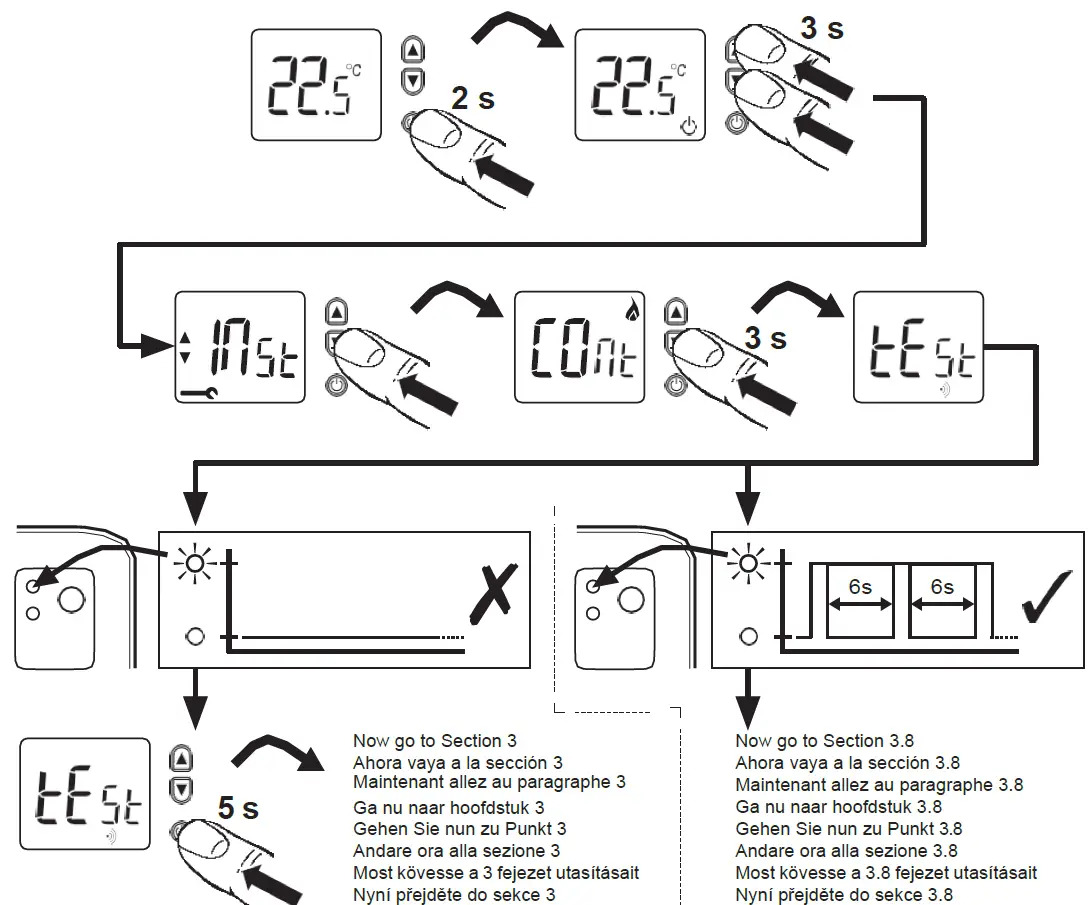
Performing a system test
You can test the system setup in ADVANCED MENU under the SYSTEM TEST option.
- Press and hold Menu on the thermostat for 5 seconds to access ADVANCED MENU options.
- Touch or go to SYSTEM TEST.
- Touch Select or touch text area.
- Touch or select system test type. Touch Select or touch text area.
- For the heat test and cool test, use or to activate each stage of the equipment. For the fan test, use or to turn the fan on and off.
NOTE: The clock is used as a timer while the stages are running. The Heat On and Cool On indicators are displayed when the system test is running.
Viewing equipment status
You can see the status of thermostat-controlled equipment in the Menu under the EQMT STATUS option.
- Touch Menu on your thermostat.
- Touch or go to EQMT STATUS. Touch Select or touch text area.
- Touch or view the statuses of all the equipment the thermostat is controlling. Depending on what features the thermostat supports or how it was installed, the Equipment Status screen reports data for the following systems:
- Heating and cooling
- Fan
- Ventilation (available on certain models only)
Troubleshooting
| Screen is blank | • Check the circuit breaker and reset if necessary. • Make sure the power switch at the heating and cooling system is on. • Make sure the furnace door is closed securely. |
| The screen is difficult to read | • Change screen brightness in the thermostat Menu. Increase brightness intensity for the inactive backlight of the thermostat screen (max. is level 5). |
| The heating or cooling system does not respond | • Touch Mode to set the system to Heat. Make sure the temperature is set higher than the Inside temperature. • Touch Mode to set the system to Cool. Make sure the temperature is set lower than the Inside temperature. • Check the circuit breaker and reset if necessary. • Make sure the power switch at the heating & cooling system is on. • Make sure the furnace door is closed securely. |
| Heat runs with cooling | • Verify there is not a wire attached to W for heat pump systems. See wiring on pages 6-7. |
Alerts and reminders
Alerts and reminders are displayed via the alert symbol and alert number in the clock area on the home screen. You can read more information about active alerts, snooze or dismiss non-critical alerts in Menu/Alerts.
| Number | Alert/Reminder | Definition |
| 164 | Heat Pump Needs Service | The heat pump needs service. Contact dealer to diagnose and service the heat pump. |
| 168 | Wi-Fi Radio Error | Wireless features are not available. Try removing the thermostat from the wallplate or power cycle at the breaker for 1 minute. If the code is still shown, please contact the dealer to replace the thermostat. |
| 170 | Internal Memory Error | The memory of the thermostat has encountered an error. Please contact the dealer for assistance. |
| 171 | Set the Date and Time | Set the date and time on your thermostat. The date and time are required for certain features to operate, like the program schedule. |
| 173 | Thermostat Temperature Sensor Error | The sensor of the thermostat has encountered an error. Please contact the dealer to replace the Thermostat. |
| 175 | AC Power Resumed | AC power resumed to thermostat after power loss. |
| 177 | Indoor Temperature Sensor Error | The wired indoor temperature sensor is not connected or there is a wiring short. Please contact the dealer for assistance. |
| 178 | Outdoor Temperature Sensor Error | The wired outdoor temperature sensor is not connected or there is a wiring short. Please contact the dealer for assistance. |
| Number | Alert/Reminder | Definition |
| 181 | Replace Air Filter (1) | Replace air filter (1). Reset the timer by touching the “dismiss” button on the thermostat screen after it is replaced. |
| 182 | Replace Air Filter (2) | Replace air filter (2). Reset the timer by touching the “dismiss” button on the thermostat screen after it is replaced. |
| 183 | Clean Humidifier Tank and Replace Water Filter | Clean the humidifier tank and replace the water filter or contact the dealer to do this for you. Reset the timer by touching the “dismiss” button on the thermostat screen after it is replaced. |
| 184 | Replace Humidifier Pad | Replace the humidifier pad. Reset the timer by touching the “dismiss” button on the thermostat screen after it is replaced. |
| 185 | Replace Dehumidifier Filter | Replace the dehumidifier filter. Reset the timer by touching the “dismiss” button on the thermostat screen after it is replaced. |
| 186 | Clean Ventilator Core | Clean ventilator core. Reset the timer by touching the “dismiss” button on the thermostat screen after it is replaced. |
| 187 | Clean or Replace Ventilator Filter | Clean or replace the ventilator filter. Reset the timer by touching the “dismiss” button on the thermostat screen after it is replaced. |
| 188 | Replace UV Bulb (1) | Replace UV Bulb (1). Reset the timer by touching the “dismiss” button on the thermostat screen after it is replaced. |
| 189 | Replace UV Bulb (2) | Replace UV Bulb (2). Reset the timer by touching the “dismiss” button on the thermostat screen after it is replaced. |
| 210 | Register Online For Outdoor Temperature | Online registration is required to receive outdoor temperature from the Internet. Outdoor temperature is needed for your current system setup. Download the Honeywell Home app to register your thermostat. |
| 388 | Register Online for Remote Access and Outdoor Temperature | Online registration is required for remote access and outdoor temperature. Download the Honeywell Home app to register your thermostat. |
| 399 | No Internet | The connection to the Internet has been lost. Please check your network settings. |
| 400 | No Wi-Fi Signal | The Wi-Fi signal has been lost. Please wait for the thermostat to reconnect or select a new Wi-Fi network. Follow steps in the Honeywell Home app |
| 508 | Wi-Fi Not Configured | Please download the Honeywell Home app and follow the steps to connect the thermostat to your Wi-Fi network. |
Specifications
Temperature Ranges
Heat: 40 °F to 90 °F (4.5 °C to 32.0 °C)
Cool: 50 °F to 99 °F (10.0 °C to 37.0 °C)
Operating Ambient Temperature 37 °F to 102 °F (2.8 °C to 38.9 °C)
Shipping Temperature –20 °F to 120 °F (-28.9 °C to 48.9 °C)
Operating Relative Humidity
5% to 90% (non-condensing)
Physical Dimensions in inches (mm) (H x W x D)
T6 Pro Smart Thermostat (TH6320WF2003):
4-5/64 x 4-5/64 x 1-1/16 (104 x 104 x 27)
T6 Pro Smart Thermostat (TH6220WF2006): 4-5/64 x 4-5/64 x 1-1/16 (104 x 104 x 27
Electrical Ratings
| Terminal | Voltage (50Hz/60Hz) | Running Current |
| W Heating | 20 Vac-30 Vac | 0.02 A-1.0 A |
| (Powerpile) | 750 mV DC | 100 mA DC |
| W2 (Aux) Heating | 20 Vac-30 Vac | 0.02 A-1.0 A |
| E Emergency Heat | 20 Vac-30 Vac | 0.02 A-0.5 A |
| Y Compressor Stage 1 | 20 Vac-30 Vac | 0.02 A-1.0 A |
| Y2 Compressor Stage 2 | 20 Vac-30 Vac | 0.02 A-1.0 A |
| G Fan | 20 Vac-30 Vac | 0.02 A-0.5 A |
| O/B Changeover | 20 Vac-30 Vac | 0.02 A-0.5 A |
| L/A Input | 20 Vac-30 Vac | 0.02 A-0.5 A |
| U | 20 Vac-30 Vac | 0.02 A-0.5 A |
Power Consumption
Backlight On: 1.48VA
Backlight Off: 0.88VA
5-year limited warranty
For Warranty, information go to http://customer.resideo.com
Regulatory information
FCC REGULATIONS
47 CFR § 15.19 (a)(3)
This device complies with part 15 of the FCC Rules. Operation is subject to the following two conditions: 1. This device may not cause harmful interference, and 2. This device must accept any interference received, including interference that may cause undesired operation.
47 CFR § 15.21 (the USA only)
Changes or modifications not expressly approved by the party responsible for compliance could void the user’s authority to operate the equipment.
47 CFR § 15.105 (b)
See https://customer.resideo.com/en-US/support/residential/codes-and-standards/FCC15105/Pages/default.aspx for additional FCC information for this product.
IC REGULATIONS
RSS-GEN
This device contains license-exempt transmitter(s)/ receiver(s) that comply with Innovation, Science, and Economic Development Canada’s license-exempt RSS(s). Operation is subject to the following two conditions: 1. This device may not cause interference. 2. This device must accept any interference, including interference that may cause undesired operation of the device.
The operation of this equipment is subject to the following two conditions: (1) this equipment or device may not cause harmful interference, and (2) this equipment or device must accept any interference, including interference that may cause undesired operation.
CAUTION: ELECTRICAL HAZARD
Can cause electrical shock or equipment damage. Disconnect power before beginning installation.
CAUTION: EQUIPMENT DAMAGE HAZARD
Compressor protection is bypassed during testing. To prevent equipment damage, avoid cycling the compressor quickly.
CAUTION: MERCURY NOTICE
If this product is replacing a control that contains mercury in a sealed tube, do not place the old control in the trash. Contact your local waste management authority for instructions regarding recycling and proper disposal.
CAUTION: ELECTRONIC WASTE NOTICE
The product should not be disposed of with other household waste. Check for the nearest authorized collection centers or authorized recyclers. The correct disposal of end-of-life equipment will help prevent negative consequences for the environment and human health.
 Resideo Technologies, Inc
- 1985 Douglas Drive North, Golden Valley, MN 55422
- 1-800-633-3991 33-00392EFS–01
- M.S. Rev. 03-21
- Printed in the United States
- Wi-Fi® is a registered trademark of Wi-Fi Alliance®
© 2021 Resideo Technologies, Inc.
All rights reserved.
The Honeywell Home trademark is used under license from Honeywell International, Inc.
This product is manufactured by Resideo Technologies, Inc. and its affiliates.
DOWNLOAD RESOURCES
- Honeywell Home TH6220WF2006 PRO T6 Smart Programmable Thermostat [pdf] Installation Guide TH6220WF2006 PRO T6 Smart Programmable Thermostat, PRO T6 Smart Programmable Thermostat, TH6320WF2003
- Read more: https://manuals.plus/honeywell-home/th6220wf2006-pro-t6-smart-programmable-thermostat-manual#ixzz7dbTDkwaS
FAQ’S
Does the Honeywell T6 Pro have Wi-Fi?
When connected to your existing WiFi, your T6 Pro Smart Thermostat can integrate with smart home Apple HomeKit and Amazon Echo, letting you adjust your temperatures as easy as you change songs on your playlist. This WiFi thermostat also works with your heating system’s stages, up to 2 Heat/1 Cool with heat pump.
Does Honeywell T6 Pro require C wire?
The T5/T6 pro Wi-Fi thermostats do require a common wire, also known as a “C” wire. The “C” or common wire allows the thermostat to power itself, instead of using batteries. It must be connected to the C or common terminal on the furnace control board.
What is the difference between a T4 and T6 thermostat?
The main difference between the two thermostats is that T6 is a smart thermostat that can be controlled remotely through the Honeywell Home app and also has a geolocation based schedule. The T4 is a non-connected programmable thermostat that can be programmed and controlled only from the unit itself.
Can I control my Honeywell thermostat from my phone?
The Honeywell Home App
Honeywell Home is compatible with the latest OS versions of iOS and Android. We suggest always checking the applicable app store (i.e. Google Play, Apple App Store) for compatibility using the device that you will install the app on.
Can I use the T6 Pro with a heat pump?
Yes. The T6 Pro is compatible with most heating, cooling and heat pump systems.
Can I use the T6 Pro with an electric baseboard heat?
No. The T6 Pro is not compatible with electric baseboard heat (120V-240V).
Can I use the T6 Pro with a fan coil system?
Yes. The T6 Pro is compatible with most heating, cooling and heat pump systems.
What color is the C-Wire?
Blue wires are also called “C” wires because they are the Common wire. C wires are necessary for any “smart” thermostat that needs to be connected to a power source 24/7, regardless of your heat pump type.
How do I reset my Honeywell thermostat without reset button?
Resetting a Honeywell Thermostat
Power off the thermostat and remove the batteries.
Put the batteries in the wrong way, with negative to positive and positive to negative.
Wait ten seconds and put them back in the correct way.
Your thermostat will be reset to factory settings.
Will low batteries affect thermostat?
When low batteries eventually die, you’ll see a black display screen, the thermostat will stop working and your heating or cooling units won’t function. The heating and cooling system cannot respond to nonexistent temperature commands.
What happens if you wire a thermostat wrong?
Potential consequences of improper installation could include: Electric shock. Blowing a circuit breaker. Damaging the thermostat unit, the electrical system or even the AC/furnace unit itself.
Does Honeywell thermostat automatically switch heat and cool?
There are programmable thermostats that automatically switch from heat to a/c and to heat again. Some Honeywell thermostats, such as the 8000 Series, have ‘auto’ setting where you can program the Heat temperature and the cool temperature and the thermostat will automatically switch from heat to cool.
VIDEO
Honeywell Home TH6220WF2006 PRO T6 Smart Programmable Thermostat
www://honeywellhome.com/
Honeywell Home BDR91 Wireless Relay Box
Installation
The BDR91 is a wireless relay box that can be used to switch valves, pumps, boilers or other heat sources as part of the range of Honeywell Home 868MHz Radio Frequency (RF) heating controls
Installation Notes:
- If a new system is being constructed, a BDR91 is added to an existing system, or a faulty unit is being replaced, the desired units must be specially configured to allow them to communicate with each other. This process is called Binding. Please refer to section 3 Binding / Rebinding Procedure.
- The BDR91 Relay Box will not communicate with other RF products that use different frequencies or communications protocols.
- The BDR91 Relay Box requires a permanent 230V~ supply.
Installing the BDR91 Relay Box
For best performance, install in an open space. Leave at least 30cm distance from any metal objects including wall boxes and boiler housing. Do not mount on metal wall boxes.
EMC compliance considerations
Keep AC mains supply/load cables separate from signal wiring. Refer to Code of Practice standards EN61000-5-1 and -2 for guidance.
Binding/Rebinding Procedure
The binding operation shown is required if any of the system components are replaced or new product added to the system.
IMPORTANT: As the BDR91 can be used with a number of wireless products a typical procedure for the DT92 is shown, for other components refer to their instructions or follow the on screen instructions.
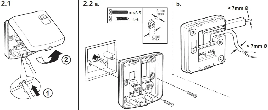
Position the unit to be paired close to the BDR91 (remove from wall if already installed)
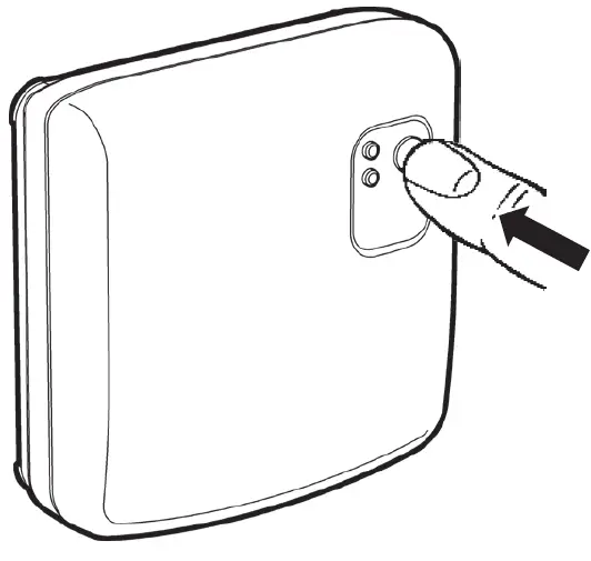
Prepare relay box, reset stored data in BDR91
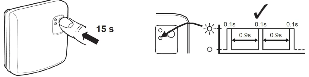
Put Relay Box into Binding Mode
If required prepare room unit by Resetting stored data (example DT92)
Put Room Unit into binding mode (see instructions for other units)
Send the binding signal
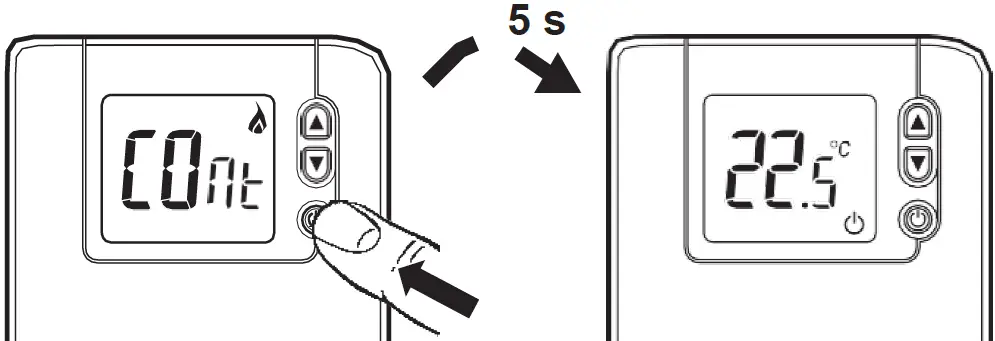
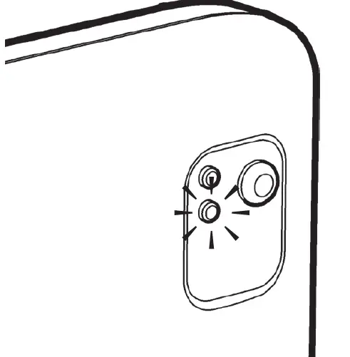
Acknowledgment of binding in BDR91
RF communication test (DT92 shown for example)
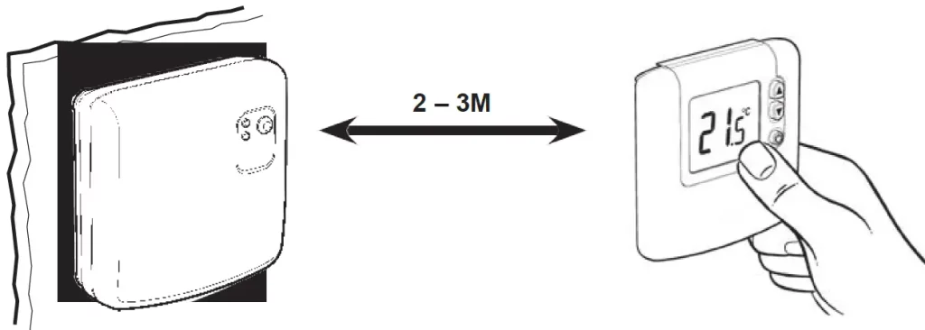
Signal Strength Test
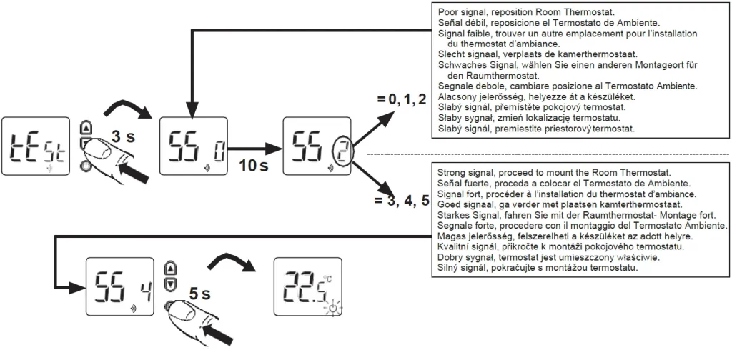
Basic System Operation
Automatic Operation
Temporary Manual Override
Press button to temporarily override the current relay position
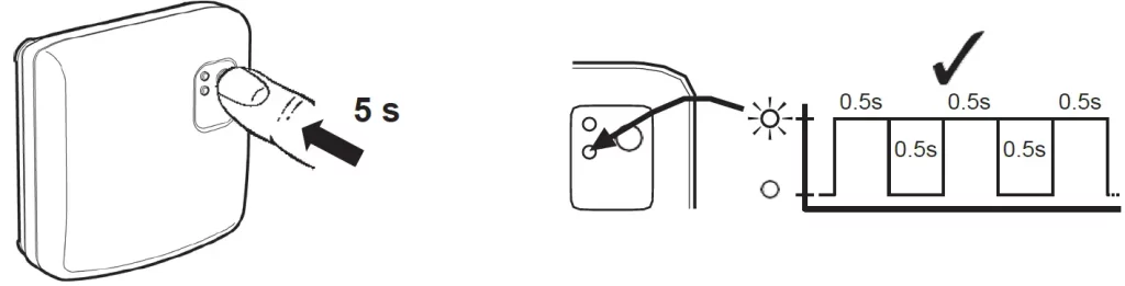
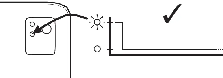
Loss of RF communications
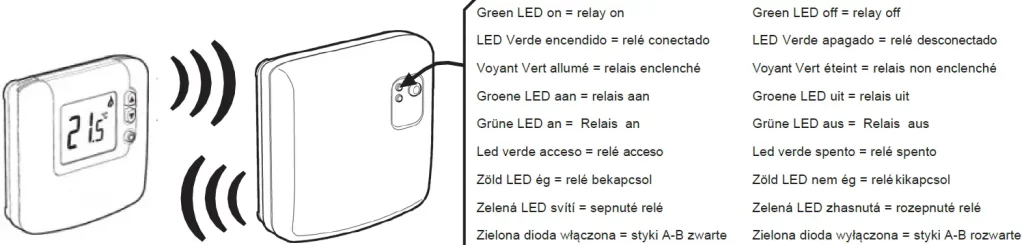
If RF communication is lost, red LED lights and Relay Box operates in failsafe mode, as set in Installer Mode
Ademco 1 GmbH
Hardhofweg 40
74821 Mosbach
Phone: +49 1801 466 388
[email protected]
homecomfort.resideo
@2020 Resideo Technologies, Inc. All rights reserved The Honeywell Home trademark is used under license from Honeywell International Inc. This product is manufactured by Resideo Technologies, Inc and its affiliates.
Manufactured for and on behalf of the Environment and Combustion Controls Division of Honeywell Technologies Sàrl, ACS-ECC EMEA, Z.A. La Pièce 16, 1180 Rolle, Switzerland, by its Authorised Representative Honeywell Inc.
![]()
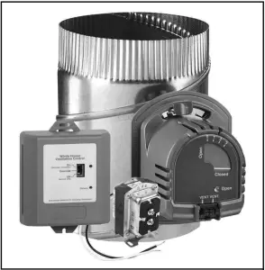
Honeywell Home W8150 Control Y8150 Fresh Air Ventilation System
FEATURES
- Designed to help meet local ventilation codes and standards, including ASHRAE 62.2-2010 standard, “Ventilation and Acceptable Indoor Air Quality in Low-Rise Residential Buildings.”
- Microcontroller optimizes the air delivery schedule to make efficient use of normal HVAC run times.
- Easy-to-use input dials allow customized ventilation for each installation.
- Test mode that includes immediate feedback to installer to confirm that air delivery requirements of selected ventilation standard are being met.
- Economical supply-only ventilation; works with forced air system.
- Can be used with other equipment, such as an HRV/ERV, for balanced ventilation.
IMPORTANT Please read these instructions and keep them in your records.
APPLICATION
The Y8150 Fresh Air Ventilation System, W8150 Fresh Air Ventilation Control provide fresh air to a home. The control operates a fresh air intake damper and, when necessary, activates the main HVAC blower to efficiently meet ASHRAE ventilation rates.
SPECIFICATIONS
Y8150 includes:
W8150A Fresh Air Ventilation Control.
EARD6TZ Fresh Air Damper.
AT120 Transformer. Mounting hardware for control.
Homeowner information label.
W8150 includes:
W8150 Fresh Air Ventilation Control.
Mounting hardware for control.
Homeowner information label.
Control (W8150A):
Power Supply: 20-30 Vac, 60 Hz.
Power Consumption: 3.5 VA at 24 Vac.
Thermostat Fan Load: 10 mA resistive at 24 Vac.
Thermostat Heat Load: 10 mA resistive at 24 Vac.
Remote Terminals: 10 mA resistive at 24 Vac.
Relay Contacts: Fan:
1.5A full load, 7.5A locked rotor at 24 Vac.
Damper: 0.6A inductive, 3.1A locked rotor at 24 Vac.
Auxiliary: 0.5A inductive, 2.5A locked rotor at 24 Vac.
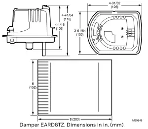
Damper (EARD6TZ): 24 Vac, 12 VA, 60 Hz.
Operation: Power-open, spring-closed.
Diameter: 6 in.
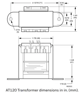
Transformer (AT120):
Input: 120 Vac.
Output: 27 Vac open circuit, 24 Vac full load at 20 VA.
Mounting: Foot mounted.
Temperature: -20 °F to 160 °F (-29 °C to 71 °C).
Humidity: 5 to 90% RH, noncondensing.
Input Setting Ranges:
Bedrooms: 2-5.
Area: 1000-4600 sq ft.
Vent Airflow: 40-160 cfm.
Composite Setting Resolution: +/- 12% of ASHRAE 62.2-2010, recommended ventilation for single-system setup.
AT120 Approvals: UL Component Recognized: Class 2, File No. E14881.
Location: Device can be installed in unconditioned space.
Multiple devices can be installed when operating multiple HVAC systems.
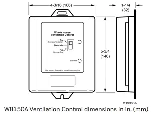
Dimensions: See device dimension diagrams.
DIMENSIONS
W8150 QUICK GUIDE
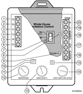
| No. | Name | Description | Function |
| 1 | GF | Equipment fan | Allows W8150 to pass thermostat calls and, when necessary, turn on system fan for ventilation. This should be the only connection to G on the HVAC equipment. |
| 2 | RC | 24 Vac cooling system power | Provides power to GF terminal to operate system fan, when necessary. |
| 3 | CC | 24 Vac cooling system common | Allows W8150 to monitor when system fan is energized. |
| 4 | CH | 24 Vac heating system common | Allows W8150 to monitor thermostat heat calls when W is energized. |
| 5 | W | Heating | Allows W8150 to monitor when heating is energized. |
| 6 | GT | Thermostat (or other control) fan terminal | Allows W8150 to monitor when GT is energized. All external equipment that controls the system fan should be wired to this terminal. |
| 7 | Switch | On (optimal ventilation) Override
Off (Remote Only) |
On (optimal ventilation) – W8150 ventilates, based on control settings. Override – W8150 runs ventilation continuously.
Off (Remote Only) – W8150 supplies ventilation only when there is a remote call. |
| 8 | Light | Green | Indicates device is powered and operating normally. Used in Test Mode to signal if dial settings meet chosen standard. |
| 9 | Light | Red | Indicates the device is not operating normally. Used in Test Mode to signal if dial settings do not meet chosen standard. |
| 10 | DIP1 | Ventilation limit | Choose between 60% (default) and 100% maximum fan run time allowed by W8150 for ventilation. |
| 11 | DIP2 | Ventilation standard | Choose between ASHRAE 62.2 (default) and 62-1999 ventilation standards. |
| 12 | BEDROOMS | Number of bedrooms | Used to calculate amount of ventilation necessary. |
| 13 | AREA (SQ FT) | Square footage of conditioned space | Used to calculate amount of ventilation necessary. |
| 14 | VENT AIRFLOW (CFM) | Air delivery rate through fresh air duct. | Used to calculate amount of ventilation necessary. |
| 15 | Test | Test button | W8150 checks dial and switch settings, activates ventilation for up to three minutes and provides feedback to validate if chosen standard can be met. |
| 16 | REMOTE | Remote switch (two terminals) | 24 Vac powered contacts allow a remote switch closure to call for ventilation. |
| 17 | AUX | Auxiliary (two terminals) | 24 Vac dry contacts allow W8150 to control an auxiliary device, such as exhaust fan or HRV/ERV, with a call for ventilation. |
| 18 | DAMPER | Damper (two terminals) | 24 Vac powered contacts control fresh air damper. |
| 19 | XFMR C | 24 Vac ventilation control common | Supplies power to W8150 and damper from transformer provided. |
| 20 | XFMR R | 24 Vac ventilation control power | Supplies power to W8150 and damper from transformer provided. |
INSTALLATION
A fresh air duct and damper must be installed between the outdoors and the return side of the HVAC equipment. The W8150 control will be mounted near the HVAC system and wired between the thermostat and the fan control.
You will need…
- W8150 Fresh Air Ventilation Control.
- damper. · transformer.
- insulated ductwork.
- outdoor weather hood.
- starting collar.
- access to 120 Vac power.
- airflow measuring tool.
TIPS:
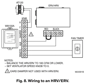
- To meet ASHRAE 62.2-2010, system must have at least a MERV 6 filter installed.
- In cold climates, balanced ventilation is recommended.
An exhaust fan or heat recovery ventilator can be used. - Humid climates may require additional dehumidification equipment.
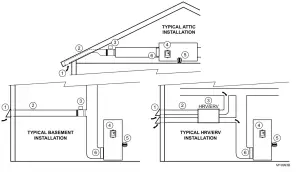
Choosing a location…
When choosing locations for equipment, duct connections, and fresh air intake, be sure to consult local code requirements.
| Device Number | Component | Location |
| 1 | Fresh air intake | Install away from known sources of pollutants such as auto exhaust, dryer vent exhaust or chimney smoke. |
| 2 | Fresh air duct | Install between weather hood and upstream of equipment filter and downstream of any duct-mounted sensor. |
| 3 | Damper | Install damper in fresh air duct, where convenient. Optionally, install heat recovery ventilator. |
| 4 | Control | Locate the control for convenient access and for easy wire routing. |
| 5 | Transformer | Locate where convenient for line voltage connection. |
| 6 | Filter | Locate filter downstream of fresh air intake. |
Installing fresh air damper, ducting, and control…
- 1. Disconnect power from HVAC system.
- Install the weather hood, ducting, and damper following local practices. Be sure all duct and insulation seams are tightly sealed.
- Mount the transformer and control.
TIPS:
- In general, larger ducting allows higher airflow, minimizes additional fan run time and may be needed for larger homes.
- Installing a damper directly to the return duct may be convenient to support the damper and reduce ducting.
- Fresh air connection should be downstream of sensors (such as a humidistat) in return air plenum.
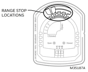
- The EARD6TZ end stops can be used to reduce the amount of airflow in the duct. To prevent complete opening, move the red tab to the desired range stop location.
Wiring the control…
 CAUTION
Electrical Hazard. Can cause personal injury or equipment damage. Disconnect power to all systems before beginning installation.
- Wire the control. See wiring diagrams in Fig. 1-10 as listed below. All wiring must comply with local codes, ordinances, and regulations.
- Reapply power to system and control.
TIP:
- Control package allows wire routing through side slots and bottom openings.
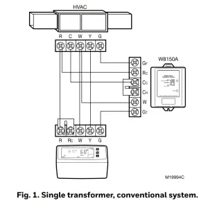
| System Hookup Diagrams | Fig. No. | Page No. |
| Single transformer, conventional | 1 | 10 |
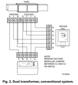
| Dual transformer, conventional | 2 | 10 |
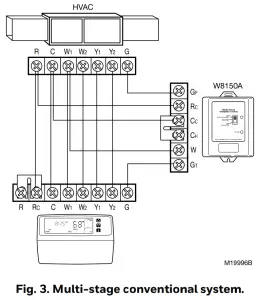
| Multi-stage, conventional | 3 | 10 |
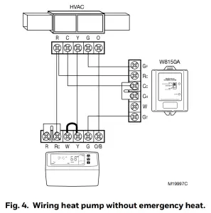
| Heat pump without emergency heat | 4 | 10 |
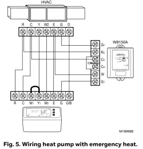
| Heat pump with emergency heat | 5 | 11 |
| Accessory Hookup Diagrams | Fig. No. | Page No. |
| Wiring with a PC8900 Thermostat | 6 | 11 |
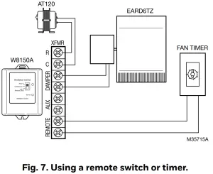
| Wiring with a remote switch/timer | 7 | 11 |
| Wiring to an HRV/ERV | 8 | 11 |
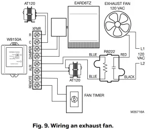
| Wiring an exhaust fan | 9 | 11 |
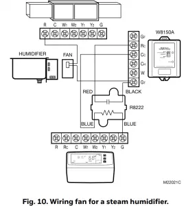
| Wiring a fan for a steam humidifier | 10 | 12 |
Measuring airflow…
- Make sure all HVAC system air filters are clean and installed.
- Push Test button:
• Control opens damper and turns on HVAC fan for three minutes.
• A red or green light is flashing; you can now measure airflow. - Follow instrument instructions for measuring airflow.
TIPS:
- You can exit the test mode at any time by pressing the test button again.
- See Conversion Table (located after wiring diagrams) for quick area and airflow setting conversions.
- For future reference, record the air flow on the inside of the device cover.
- Pitot Tubes and flow measuring stations are commonly used airflow measuring devices.
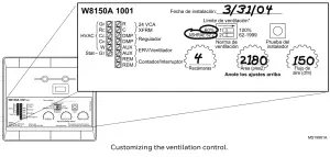
About the control settings…
Dial Settings
These settings allow the installer to customize the control to meet the ventilation requirements for the home.
Ventilation Standard
Building codes are different everywhere. The W8150 Ventilation Control can be configured to operate based on:
- ASHRAE 62.2.
- ASHRAE 62-1999
TIP:
- Clear understanding of local codes and practices is required to make sure the ventilation system is installed and configured correctly. Generally, ASHRAE 62.2 control method is recommended and can meet many existing local codes.
Code/Standard Setting General Ventilation Requirements ASHRAE 62.2 Washington State Energy Code ASHRAE 62.2 Canadian Building Code* ASHRAE 62.2 Minnesota Energy Code 62-1999 2002 International Residential Code 62-1999 *In Canada, interlocking exhaust equipment may be required for balanced ventilation.
Ventilation Limit
This setting determines the maximum amount of time that the fan runs for ventilation.
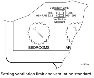
Setting ventilation limit and ventilation standard.
Setting the control…
- Be sure power is turned on.
- Set the Ventilation Standard on the control.
- Set the bedrooms dial.
- Set the area (sq ft) dial.
- Set the airflow (cfm) dial.
- Press the test button and observe the lights:
Green light is flashing.
The dial settings meet the chosen standard.
Red light is flashing.
There is not enough fresh air delivered to meet the requirements of the selected standard. See Troubleshooting section. - Record settings on the label inside the cover as shown in the diagram.
TIPS:
- Ventilation control reads new dial setting only when test button is pushed or power is cycled. To ensure dial settings are read, push test button after any changes are made.
- For single bedroom homes, set the bedrooms dial to 2 (this may result in more ventilation than the minimum required).
- For homes having more than five bedrooms and only a single ventilation system, set the bedrooms dial to 5 (this may result in less ventilation than the minimum required).
- For conditioned square feet, set area (sq ft) dial to the nearest value.
- For airflow, set airflow (cfm) dial to the nearest value. · Vaulted ceilings do not need to be considered when
setting this control. - For homes with multiple systems: Resideo
recommends a ventilation control and fresh air intake for each system. Measure ventilation airflow for each system independently. Refer to Multi-system Setup Example for further details.
CHECKOUT
In this section, make sure the ventilation system is operating correctly.
- On thermostat, set Fan switch to Auto and System switch to Off.
- Set any remote switches throughout the house in the Off position.
- On the W8150, set the control switch to Off (remote only).
- Press Test button for two seconds to enter test mode:
• A light on the control begins flashing.
• The HVAC system fan comes on.
• The damper moves to the Open position. - Press the Test button again to exit test mode:
• No lights on the control are on.
• The HVAC system fan turns off.
• The damper returns to the closed position. - Return the thermostat, ventilation control, and remote switches to the original settings.
- Refer to Troubleshooting section, if needed.
TIP:
- W8150 Ventilation Control automatically exits test mode after three minutes.
TROUBLESHOOTING
| Problem | Possible cause | What to do |
| Flashing red light during test mode (The current settings do not meet the selected ventilation requirement) | Not enough airflow |
|
| Ventilation on-time limit setting |
|
|
| Flashing red light during normal operation | Low voltage |
|
No light on ventilation control when switch set to:
|
No power to control |
|
| Device malfunction |
|
|
| HVAC fan does not come on after pressing Test button. | Wiring |
|
| HVAC system does not have power |
|
|
| HVAC fan is running all the time | Device is set to override |
|
| Remote switch is on |
|
|
| Thermostat Fan switch is in On position |
|
|
| HVAC system is running to satisfy heating or cooling requirements. |
|
|
| Ventilation limit is set to 100% ventilation limit. |
|
|
| Low ventilation air flow. |
|
|
|
Incorrectly wired. |
|
| Transformer output. |
|
|
| Damper actuator motor failure or mechanical failure. |
|
|
| Cooling compressor comes on when there is no cooling call from the thermostat. | Incorrectly wired. |
|
| Not enough airflow | Obstruction or duct size |
NOTE: After any changes to the ductwork, repeat the Measuring Air- flow section. |
WIRING DIAGRAMS
Consult thermostat Installation Instructions for alternate terminal designations.

Multi-System Setup Example
Total square feet and bedrooms should be proportionately split between the ventilation controls based on sq ft served by each system regardless of where the bedrooms are located.
Example: 5,000 sq ft, six bedrooms:
System 1:
- serves 3200 sq ft,
- two bedrooms.
- fresh air intake measured at 127 cfm.
System 2:
- serves 1800 sq ft,
- four bedrooms
- fresh air intake measured at 98 cfm.
Set W8150 for System 1:
- 3100 sq ft,
- four bedrooms
- 130 cfm.
Set W8150 for System 2:
- 1900 sq ft,
- two bedrooms
- 100 cfm.
CONVERSION TABLE
| Area | Airflow | ||
| sq ft | sq m | cfm | lps |
| 1000 | 93 | 40 | 19 |
| 1300 | 121 | 50 | 24 |
| 1600 | 149 | 60 | 28 |
| 1900 | 177 | 70 | 33 |
| 2200 | 204 | 80 | 38 |
| 2500 | 232 | 90 | 42 |
| 2800 | 260 | 100 | 47 |
| 3100 | 288 | 110 | 52 |
| 3400 | 316 | 120 | 57 |
| 3700 | 344 | 130 | 61 |
| 4000 | 372 | 140 | 66 |
| 4300 | 399 | 150 | 71 |
| 4600 | 427 | 160 | 76 |
| Airflow | ||||
| cfm | 6 in. duct (15.2 cm) | 7 in. duct (17.8 cm) | ||
| fpm | ms | fpm | ms | |
| 40 | 204 | 1.0 | 150 | 0.8 |
| 50 | 255 | 1.3 | 187 | 1.0 |
| 60 | 306 | 1.6 | 225 | 1.1 |
| 70 | 357 | 1.8 | 262 | 1.3 |
| 80 | 407 | 2.1 | 299 | 1.5 |
| 90 | 458 | 2.3 | 337 | 1.7 |
| 100 | 509 | 2.6 | 374 | 1.9 |
| 110 | 560 | 2.8 | 412 | 2.1 |
| 120 | 611 | 3.1 | 449 | 2.3 |
| 130 | 662 | 3.4 | 486 | 2.5 |
| 140 | 713 | 3.6 | 524 | 2.7 |
| 150 | 764 | 3.9 | 561 | 2.9 |
| 160 | 815 | 4.1 | 599 | 3.0 |

Resideo Technologies, Inc.
1985 Douglas Drive North, Golden Valley, MN 55422 1-800-468-1502
68-0282–11 M.S. Rev. 04-20 | Printed in United States
© 2020 Resideo Technologies, Inc. All rights reserved.
The Honeywell Home trademark is used under license from Honeywell International, Inc. This product is manufactured by Resideo Technologies, Inc. and its affiliates.

Honeywell Home T4R Wireless Programmable Thermostat
Honeywell Home T4R Wireless Programmable Thermostat
Thermostat Interface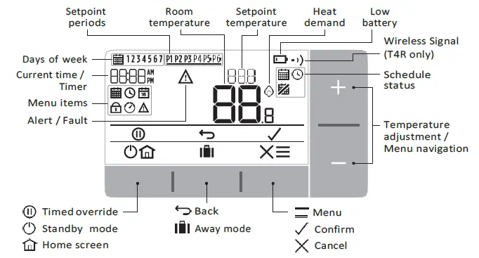
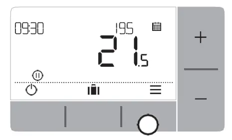
Status Icons
Schedule On: Programmed schedule is active.
Schedule Override: Active until next scheduled period starts or the timed override duration has ended.
Schedule Off: Programmed schedule is turned off.
Low Battery: Power has reached approximately 10% – flashes when critically low (see Changing the Batteries).
Heat Demand: Room temperature is below setpoint – indicating there is a demand for heating (boiler activity might occur).
Wireless Signal: Thermostat (T4R only) is connected to the Receiver Box.
Menu & Navigation Icons
Menu: Options and settings of your Thermostat:
- Heating schedule
- Clock
- Date
- Keypad lock
- Optimisation
- OpenTherm® boiler alerts (T4M only) Back: Return to the previous screen/menu. Confirm: Confirm a change or selection.
Cancel: Reject a change without saving.
Timed override: Set a timed duration for the override.
Standby: Turns the heating on or off.
Away mode: Turns the heating off for a set number of days.
Home: Returns you directly back to the home screen.
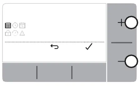
Navigating the menu
- Press button to enter the main menu.
- Press or buttons to select a menu item – the selected item will flash.
- Press to confirm the selection.
- Press or to adjust a setting and
- press to save change or advance to next selection.
- press to go back to previous selection.
- press to save change and return to home screen.
Menu
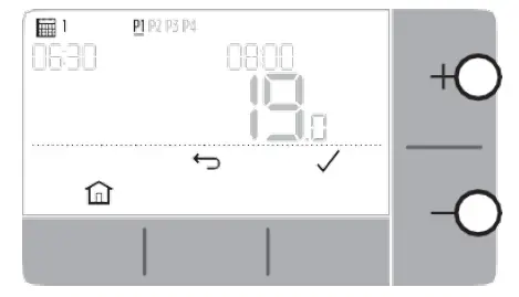
Heating schedule
Your Thermostat comes with the following default schedule. Follow the next steps to adjust the programmed schedule.
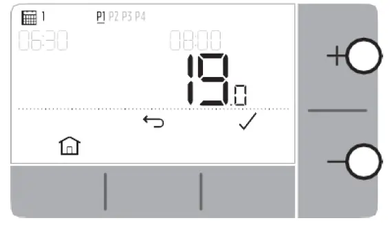
| Days 1 to 5 (Mon to Fri) | Days 6 & 7 (Sat & Sun) | |||
| Period | Time | °C | Time | °C |
| P1 | 6:30 – 8:00 | 19 °C | 8:00 – 10:00 | 19 °C |
| P2 | 8:00 – 18:00 | 16 °C | 10:00 – 17:00 | 16 °C |
| P3 | 18:00 – 22:30 | 21 °C | 17:00 – 23:00 | 21 °C |
| P4 | 22:30 – 6:30 | 16 °C | 23:00 – 8:00 | 16 °C |
- Press to enter the main menu.
- Press or to select the schedule menu and press
- Press or to select EDIT and press.
- Press or to select the day to be adjusted and press
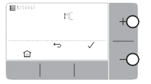
- Press or to select the period to be adjusted and press
- Press or to adjust the start time and press
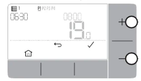
- Press or to adjust the end time and press
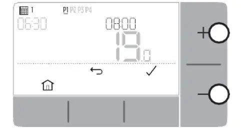
- Press or to adjust the temperature and press
- Repeat these steps to make adjustments to the remaining periods and days or press to save changes and return to the home screen.
Clock
To make adjustments to the clock format or time.
- Press to enter the main menu.
- Press or to select the Clock menu and press
- Press or to change the clock format and press
- Press or to adjust the time and press
Date
To make adjustments to the date – Year/Month/Day.
- Press to enter the main menu.
- Press or to select the Date menu and press
- Press or to adjust year and press
- Press or to adjust month and press
- Press or to adjust day and press
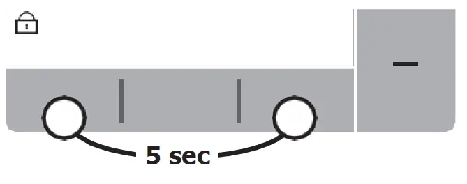
Keypad lock
You can lock the keypad to prevent unnecessary adjustments to the Thermostat.
- Press to enter the main menu.
- Press or to select the Keypad lock and press to activate it.
- To unlock the Keypad press and hold the Left and Right buttons for 5 sec.
- To lock the Keypad repeat step 2.
Optimisation
Your Thermostat has optimisation functions that aim to save energy while maintaining suitable comfort levels. The Thermostat displays during the optimisation period if set.
- Optimum Start learns how long it takes your home to reach a set temperature and then turns the heating on a bit earlier to achieve that temperature at the programmed time.
- Delayed Start saves energy by slightly delaying the start of heating depending on the difference between the set temperature and the room temperature.
The closer these temperatures are the longer it will delay the start. - Optimum Stop saves energy by switching off a little bit earlier than the programmed time. If your home is up to temperature, you will not notice the effect on the temperature, but you should see a difference in your fuel bill.
To enable or disable an optimisation function:
- Press to enter the main menu.
- Press or to select the Optimisation menu and pre
- Press or to select an option and press
- 0:8P for Optimum Start or Delayed Start
- 0:9S for Optimum Stop
- Press or to change the optimisation function and press
-
- 0:8P 0 = Optimum Start disabled
- 0:8P 1 = Optimum Start enabled
- 0:8P 2 = Delayed Start enabled
- 0:9S 0 = Optimum Stop disabled
- 0:9S 1 = Optimum Stop enabled
-
- Press to save changes and return to the home screen.
OpenTherm® boiler alerts (T4M only)
If you have T4M Thermostat fitted to an OpenTherm® boiler, you can view alerts received form the boiler about your heating system.
- Press to enter the main menu.
- Press or to select the Open Therm alerts menu and press
- Press or to cycle through the list of boiler alerts.
- Press to return to the home screen.
Standby mode (with frost protect)
Save energy by switching the heating off when not required – e.g. during warmer summer months, or when doors and windows are open for extended periods of time. If the temperature drops to 5°C the heating will come on to prevent the heating pipes freezing.
- Press to switch the heating off – the display will show OFF.
- Press a gain to switch the heating on – the display will show .
Away mode
Save energy by switching the heating off for a set period of time while you are away from home – and back on again in time for your return.
- Press to enter the away mode menu.
- Press or to select the number of days you will be away and press
- Press or to set the temperature while you are away and press
- To cancel Away mode press again from the home screen.
Schedule Override
During normal use your Thermostat will follow the programmed schedule – indicated by the icon. There are a few ways you can override the schedule to suit your current needs.
Temporary Override
Set until next programmed setpoint is reached.
- Press or to set the new desired temperature. The programmed schedule will resume at the next programmed setpoint.
Timed Override (1 or 2 hours)
Can be used to Boost (increase) the heating for a short period or as an
Economy (decreased) setting if leaving the house for a short period.
- Press or to set the new desired temperature and press to activate the timer.
- Press or to select 1 or 2 Hours and press
- To cancel the timed override press again from the home screen.
Turn Schedule Off (Manual Mode)
Turn the heating schedule off and permanently follow a single (adjustable) temperature – until the schedule is turned on again.
- Press or to select the schedule menu and press
- Press or to select OFF and press
- Press or to adjust the permanent temperature.
- Repeat above steps and choose ON to follow the schedule.
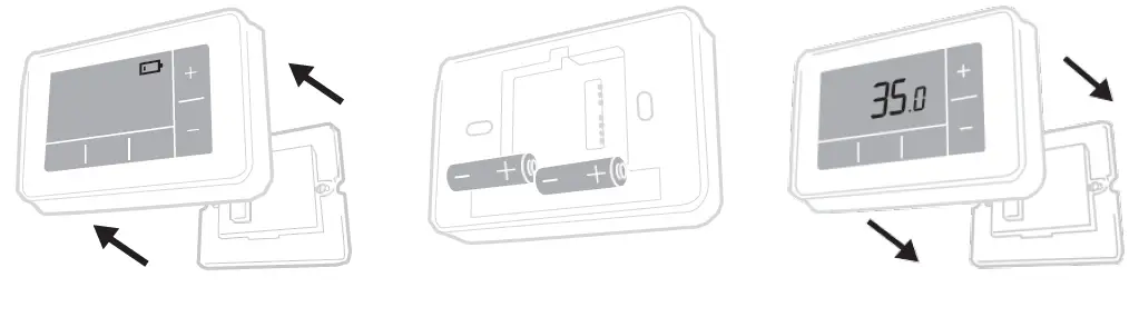
Changing the Batteries (T4 & T4R only)
The Thermostat is powered by batteries, although a battery icon is not shown on the display during normal use. The only time you will see the battery icon is when they get low on power.
- is displayed when battery power has reached approximately 10% – you should be prepared to change them soon.
- + will flash when battery power has become critically low – you should change them immediately to make sure there is no disruption to your heating system.
- Replace with 2 new 1.5V LR6 AA Alkaline batteries only – which should last approximately 2 years depending on Thermostat use.
- Pull Thermostat off the wall bracket or table stand.
- Remove old batteries and insert new ones.
- Clip Thermostat onto wall bracket or table stand.
Please help to protect the environment by recycling old batteries in accordance with local regulations.
Wireless Receiver Box (T4R only)
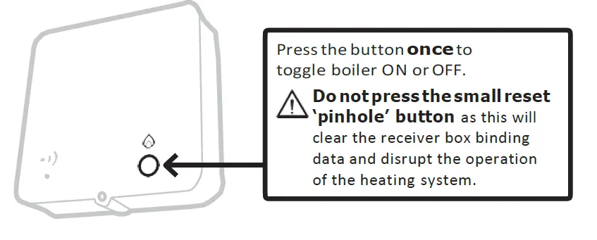
The T4R Thermostat communicates wirelessly to the Receiver Box which is wired to the boiler. If the Thermostat loses wireless communication or becomes faulty, the boiler can be switched on or off manually using the button on the Receiver Box
- is displayed on the Thermostat when the wireless signal is good – The receiver box LED will be solid GREEN.
- + will flash on the Thermostat when the wireless signal is lost – The Receiver Box LED will flash RED.
- If communication is lost move the Thermostat to another location to try and restore communication.
To manually override the boiler using the Receiver Box:
- Press the button once to switch the boiler ON or OFF. The button LED should be:
- Solid YELLOW when the boiler is ON.
- Off when the boiler is OFF.
Troubleshooting
If you have difficulty with your Thermostat, try these suggestions. Most problems can be corrected quickly and easily.
| All models | |
| Screen is blank | Replace the batteries (T4 & T4R only).
Check the OpenTherm boiler has power (T4M only). Contact installer. |
| Thermostat shows | Batteries have less than 10% power and need to be replaced soon. |
| Thermostat is flashing + | Batteries are critically low and need to be replaced immediately – see ‘Changing the Batteries’. |
| Thermostat shows but the boiler does not switch on. | The boiler cycles on and off as it controls the temperature, and sometimes the icon will be displayed when the boiler has cycled off.
If the boiler doesn’t switch on after a long period of time contact your installer |
| Heating system does not respond to temperature adjustments. | Make sure the set temperature is higher than the actual room temperature.
Check the heating system is powered on. Check the Receiver Box is powered and the Thermostat has a wireless signal (T4R only). |
| Thermostat shows | The temperature sensor of your Thermostat is faulty, contact your installer to repair
or replace the Thermostat. |
| T4R (Wireless) Thermostat & Receiver Box only | |
| Thermostat is flashing + and Receiver Box LED is flashing RED. | Wireless signal lost – Move the Thermostat to another location to try and restore communication. |
| Thermostat is flashing + and Receiver Box LED is off. | Check Receiver Box has power by pressing the button to switch boiler on.
If Receiver Box has power then no wireless binding data stored – Follow binding procedure in the installation guide or contact your installer. |
| Receiver Box LED is flashing ORANGE. | Receiver Box is in binding mode – will time out of this mode after 3 minutes. |
| T4M (OpenTherm) Thermostat only | |||
| An OpenTherm boiler can report alerts back to the Thermostat which can be useful when contacting an installer or maintenance engineer. You can view these in the ‘OpenTherm® boiler alerts’ menu. | |||
| Description | ID | Error code | OT Reading |
| Service request | 001 | 01SR | 0 = service not required 1 = service required |
| Low water pressure | 002 | 02WP | 0 = no WP fault 1 = WP fault |
| Gas/flame fault | 003 | 03GF | 0 = no GF fault 1 = GS fault |
| Air pressure fault | 004 | 04AF | 0 = no AP fault 1 = AP fault |
| Water Over Temperature | 005 | 05WT | 0 = no OVT fault 1 = OVT fault |
| OEM specific | 006 | 06OS | Boiler manufacturer specific code |
@2020 Resideo Technologies, Inc. All rights reserved The Honeywell Home trademark is used under license from Honeywell International Inc. This product is manufactured by Resideo Technologies, Inc and its affiliates.
DOWNLOAD RESOURCES
- Honeywell Home T4R Wireless Programmable Thermostat [pdf] User Guide T4R, T4, T4M, Wireless Programmable Thermostat
- Read more: https://manuals.plus/honeywell-home/t4r-wireless-programmable-thermostat-manual#ixzz7gUUJ2GSg
- Honeywell Home T4R Wireless Programmable Thermostat [pdf] Installation Guide T4R, Wireless Programmable Thermostat
- Read more: https://manuals.plus/honeywell-home/t4r-wireless-programmable-thermostat-manual#ixzz7gUUNq3ep
FAQ’S
Why is my heating not working?
Check that the power is on and that the thermostat is connected to the receiver box. If it still does not work, check the batteries. If they are low, replace them with new ones.
Why do I have to press so many times to get to a certain menu?
This is a security feature designed to prevent accidental changes to your settings. You will need to press more than once for each menu item you wish to change.
Why does my boiler keep running when I’m out?
The Open Therm® system uses a demand control system which means that if you have set your thermostat to be away while you are out, then your boiler will only start when it detects a temperature drop in your home. This helps save energy and money as well as reducing wear and tear on your boiler and hot water cylinder.
How do I connect my Honeywell thermostat to WiFi?
Connecting A Honeywell Thermostat To WiFi
Press the “Menu” button.
Press the “WiFi Setup” button.
The thermostat will scan the WiFi networks in the area and display a list of the networks.
Touch to select your network from the list.
The screen will present you with a field to enter your WiFi password.
How do I set the temperature on my Honeywell thermostat?
If you have a manual thermostat, setting the temperature on your Honeywell thermostat is simple. All you need to do is to press the up and down buttons to set the temperature. The temperature you set will stay until you change the temperature again.
What does C mean on Honeywell thermostat?
common wire
Known as the common wire, (C-Wire) provides Wi-Fi thermostats continuous power from heating (e.g. furnaces) and cooling systems (e.g. Air Conditioning systems). C-Wires are required on all Resideo Wi-Fi thermostats.
Why is my Honeywell wireless thermostat not working?
If your Honeywell Thermostat isn’t turning on, make sure to first try new batteries. If that doesn’t work, check the thermostat for any loose wires and check your circuit breaker. If all else fails, you can perform a hard reset on the Honeywell Thermostat to set it back to factory settings.
How do I troubleshoot my Honeywell thermostat?
Troubleshooting a Programmable Honeywell Thermostat
Put in new batteries; Check the circuit breaker; Check the indoor unit to make sure all the panel doors are closed; Make sure the power is connected to the furnace or air conditioning unit by checking the switch near the indoor unit is up.
Why is there a red light on my Honeywell thermostat?
If you notice a red light coming from your thermostat during regular operation, this usually means that the outdoor unit shut itself off due to a problem and is locked out from normal operation. When this happens, the outdoor unit sends a signal to the thermostat to let you know there is a problem with the unit.
Why can’t I change the temperature on my Honeywell thermostat?
One of the most common causes of a thermostat not reaching the set temperature is a damaged or broken sensor. When a sensor is the issue, the thermostat’s reading of the surrounding temperature will be incorrect.
How do I clean my Honeywell thermostat?
Using a clean, soft paintbrush and a gentle touch, dust the inner workings of the thermostat. For grime or debris at points where the electronic components touch, slide an open dollar bill like dental floss between them to loosen and remove it. An alternative tool is compressed air.
Can I move my Honeywell thermostat to another room?
If you want to move your thermostat to a more convenient spot that’s OK, but it should stay in its new location long term, and make sure that you place it according to the following guidelines. If you move your thermostat across the room or to another room entirely, it will need time to learn about its new spot.
Honeywell Home T4R Wireless Programmable Thermostat
www://honeywell.com/us/en
![]() HZ322 TrueZONE®
HZ322 TrueZONE®
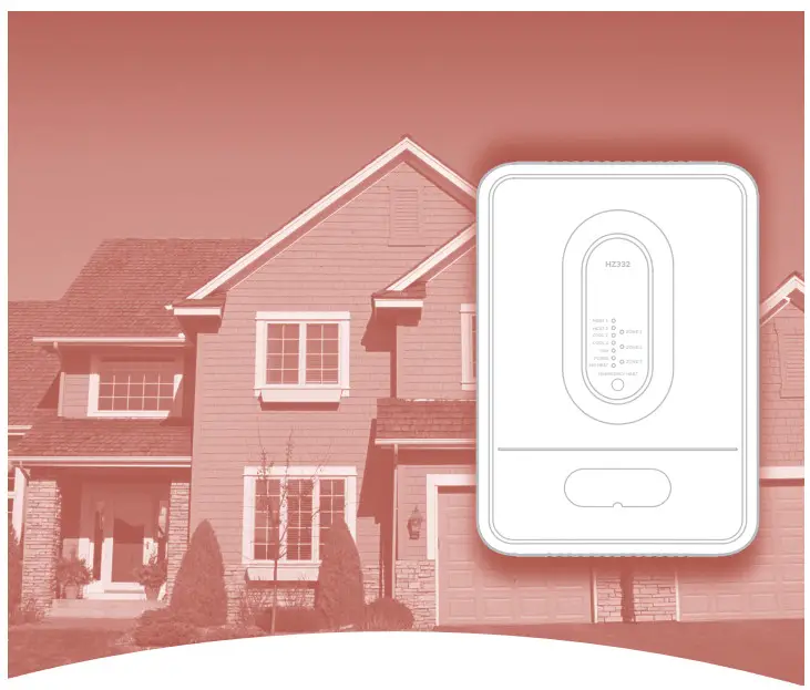
Zone Panel Professional Installation Guide

SPECIFICATIONS
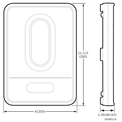
Input Ratings:
Voltage: 18 VAC – 30 VAC 50 Hz/60 Hz transformer of 40 VA or more.
Current Draw:
Zone Panel: 7.5 VA max.
THM4000R Wireless Adapter: 2 VA max.
All VA specifications at 24 VAC.
Wiring:
18- or 20-gauge solid (not stranded) wire.
Humidity Ratings:
5% to 90% RH non-condensing.
Temperature Ratings:
Shipping: -20°F to 150°F (-29°C to 66°C)
Operating: -40°F to 165°F (-40°C to 74°C)
Dimensions:
See Fig. 1.
Emissions:
Complies with FCC Class B, part 15 requirements.
Need Help?
For assistance with this product please visit customer.resideo.com and/or call Zoning Hotline toll-free at 1-800-828-8367
Read before installing.
U.S. Registered Trademark. US Pat D562,261; D563,325; 7,558,648; 7,645,158; 7,693,591; 7,693,583; 7,766,246; 7,819,331; 7,904,830; 7,913,180; 7,957,839; 9,310,091 and other patents pending. Copyright © 2020 Resideo Technologies, Inc. All rights reserved.
APPLICATION
The HZ322 TrueZONE® panel controls:
- Conventional gas, oil, or electric forced-air systems up to 2 stages heat and cool;
- Heat pump systems with single-stage compressor and auxiliary heat, and two-stage heat pumps with no auxiliary heat.
- 2 or 3 forced-air zones with wired thermostats, or wireless thermostats using THM4000R wireless adapter.
Please refer to TrueZONE Panel Frequently Asked Questions form 50-9694 for operating details.
customer.resideo.com
Table 1. Recommended Thermostats.
| System | Thermostat |
| Single-stage | TH1110D2009 (non-programmable) TH4110U2005 (Programmable) |
| 2H/1C conventional |
TH6220U2000 (Programmable) TH6220WF2006 (Programmable, Wi-Fi) |
| 2H/2C conventional |
TH6220U2000 (Programmable) TH6220WF2006 (Programmable, Wi-Fi) |
| 2H/1C heat pump | TH4210U2002 (Programmable) TH6210U2001 (Programmable) |
| All the above | TH6220U2000 (Programmable) TH6220WF2006 (Programmable, Wi-Fi) TH6320WF2003 (Programmable, Wi-Fi) TH8321WF1001 (Programmable, Wi-Fi) THX321WFS2001W (Programmable, Wi-Fi) |
| Wireless * | TH5320R1002 TH6320R1004 TH8320R1003 |
- For RedLINK™ wireless devices, a THM4000 is required.
Table 2. Recommended Dampers.
| Type | Damper | Round | Rectangular |
| Zone | Spring-open/power-closed | ARD (8 VA) | ZD (8 VA) |
| Power-open/power-closed | MARD/RRD (2 VA) | — | |
| Bypass | Constant pressure regulating damper | CPRD (0 VA spring actuator) | — |
| Modulating automatic round damper | MARD (2 VA) | — |
Table 3. Recommended Commercial Dampers.
| Type | Actuation | Round |
| Zone | Power-open/power-closed | MARD |
| Bypass | Power-open/power-closed | MARD with SPC |
Table 4. Maximum Dampers.*
| Ambient Temp. | Maximum Damper VA per Zone |
| 100°F (38°C) | 28.8 |
| 160°F (71°C) | 16.8 |
- Use an SDCR (Slave Damper Control Relay) for additional dampers.
Maximum dampers per panel are limited by transformer size.
Ensure the transformer is large enough to power the panel (7.5 VA) and dampers.
Table 5. Accessories.
| Accessory | Description |
| 40 VA transformer* | AT140A1042* |
| 75 VA transformer | AT175A1008 |
| Discharge Air
Temperature Sensor * |
DATS C7735A1000* |
| SDCR** | Slave Damper Control
Relay |
| Wireless Adapter*** | THM4000R1000 |
| Wireless Outdoor Air Temperature Sensor*** | C7089R1013 |
| Portable Comfort Control*** | REM5000R1001 |
| RedLINK Internet
Gateway*** |
THM6000R7001 |
* Included in HZ322K kit.
** Use an SDCR (Slave Damper Control Relay) to add additional dampers to a zone to surpass the maximum Damper VA rating per Zone.
*** For RedLINK™ wireless devices, a THM4000 is required.
MOUNTING
- Mount the HZ322 TrueZONE panel near the HVAC equipment; locate it on a wall, stud, roof truss, or cold air return.
NOTE: The HZ322 TrueZONE panel can be mounted in any orientation; level it for appearance only.
- Separate the zone panel cover from the base, and use the base as a template to drill mounting holes.
Attach the base to the wall, stud, roof truss, or duct with appropriate screws (not included).
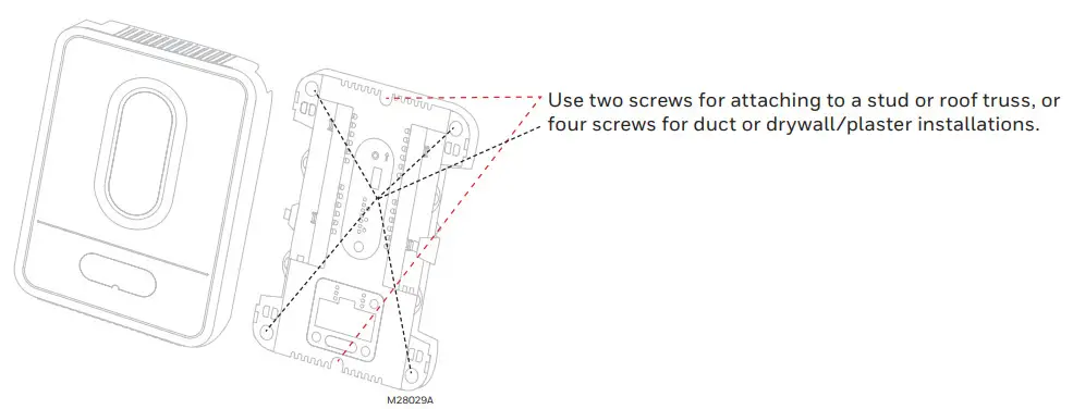
CAUTION: Voltage Hazard.
Can cause electrical shock or equipment damage. Disconnect power before beginning installation.
Wire the entire panel before applying transformer power.
Follow these steps for wiring all systems. However, the wiring will vary depending on the equipment. For conventional systems, refer to page 5. For heat pump systems, see page 6. Wiring must comply with applicable codes, ordinances, and regulations. Use the following wiring diagrams to wire the zone panel to the thermostats and dampers. - Install thermostats using instructions provided with thermostats.
Connect thermostat to zone panel. To connect the wire to the panel, strip approximately 1/4 in. of insulation and push wire into the terminal. To release wire, press the button on to-p of the terminal. In retrofit applications, trim end of wire if not straight.
 The HZ322 offers many innovations for wire management and organization: wires can be run behind the panel, through wire channels on its sides, and must be attached to a wiring anchor with a cable tie.
 - Install dampers using instructions provided with dampers. Connect dampers to zone panel.
NOTE: Multiple dampers can be wired in parallel.
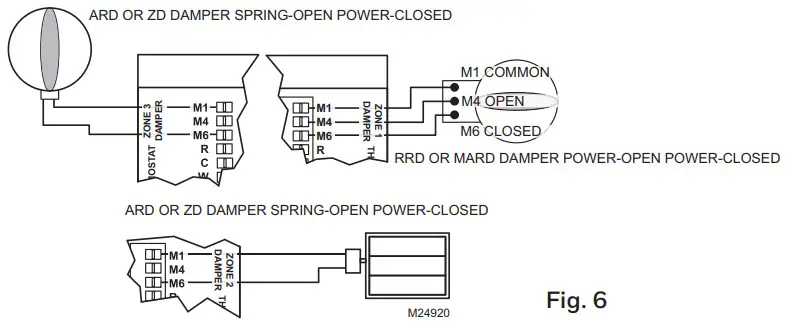 WIRING
 - Connect DATS as shown. See high and low limit settings in Table 5 “Advanced Configuration” on page 8.
For the placement of DATS in the supply duct and troubleshooting assistance with the DATS, see the Discharge Air Temperature Installation InstructionsForm Number 69-1521.
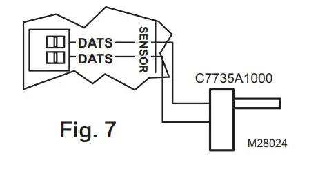
- Connect the equipment as shown here and on pages 5 and 6.
For oil heat with a separate transformer for cooling, remove this jumper. For other systems leave the jumper in place and wire to the HVAC R terminal with 18 gauge solid wire.
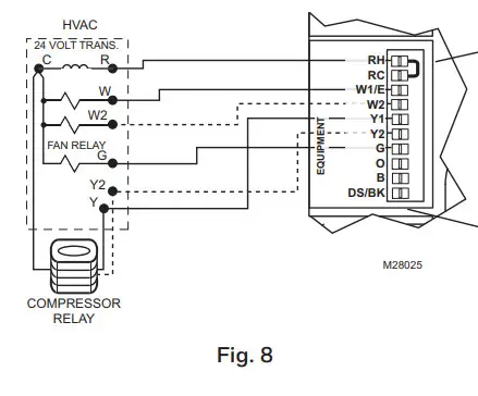 The DS/BK terminal is used with a variable-speed fan. If the HVAC equipment has a DS, BK, ODD, or DHUM terminal, wire that terminal to the HZ322 DS/BK terminal. When 2 or 3 zones are calling for cooling this terminal will be energized which will run the blower fan at the normal speed. When only 1 zone is calling for cooling the fan runs at a reduced speed which will require less air to be bypassed. Refer to HVAC equipment manufacturer instructions.
 - When a wireless thermostat, Portable Comfort Control, wireless outdoor air temperature sensor, or other RedLINK™ wireless device is used, wire the THM4000 Wireless Adapter Module to the ABCD terminals on the zone panel.
 CAUTION: Only the THM4000R can be wired to the A-B-C-D terminals on the HZ322. Do not wire the A-B-C-D terminals of the THM5320R or THM5421R Equipment Interface Module to the A-B-C-D terminals on the HZ322 zone control panel. Doing so will damage the components.
 - Connect a dedicated transformer as shown.
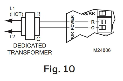
CONVENTIONAL
The following diagram is an overall view of wiring for a conventional system as depicted in steps 3–8.
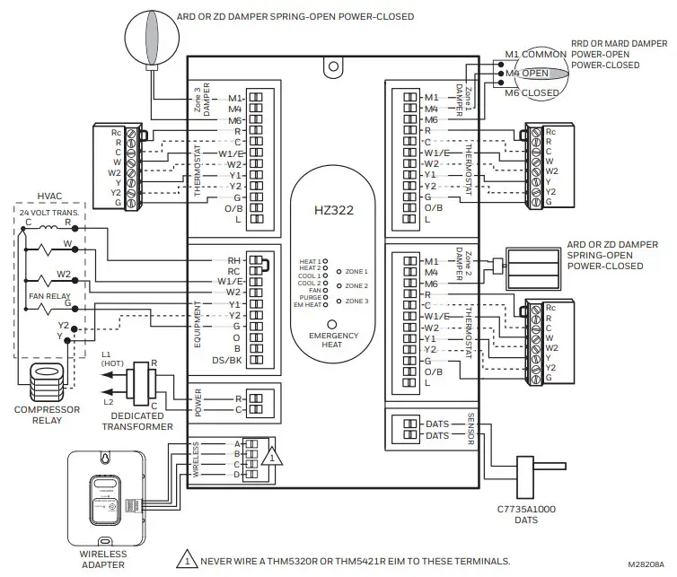
Fig. 11. Zone panel wiring—conventional.
HEAT PUMP
Use the following diagram for wiring a heat pump with electric auxiliary heat.
NOTE: You can use a conventional thermostat for a heat pump system; however, em heat can only be controlled by heat pump thermostats. The diagram below shows a heat pump thermostat used with a heat pump system.
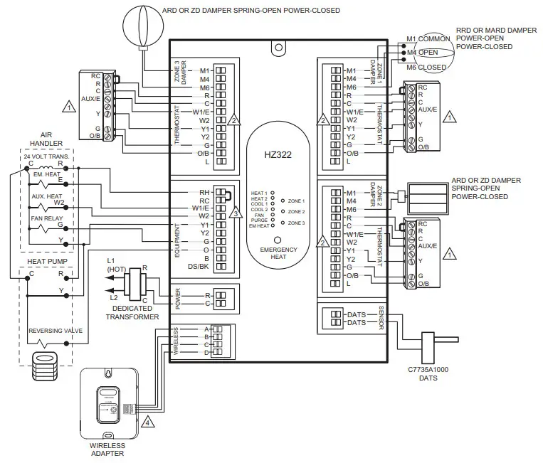
Fig. 12. Zone panel wiring—heat pump with electric auxiliary heat.
- ADD A JUMPER FROM W1/E TO W2 AT EACH ZONE.
- FOR THERMOSTATS WITH SEPARATE 0 AND B TERMINALS, ATTACH 0 FOR COOL CHANGEOVER OR ATTACH B FOR HEAT CHANGEOVER.
- IF HVAC EQUIPMENT USES THE SAME SOURCE OF HEAT FOR AUXILIARY AND EMERGENCY HEAT, JUMPER W1/E AND W2.
- ABCD TERMINALS FOR THE THM4000R WIRELESS ADAPTOR ONLY. NEVER WIRE A THM532OR OR THM5421R EIM TO THESE TERMINALS.
CONFIGURATION
To enter Configuration:
- Press the Mode button (the Config LED will light up).
- Use the Back and Next buttons to navigate through the configuration settings. Scroll through the selection choices by using the “Adjust Setting” Left and Right arrow buttons. Pressing Next enters the selected option for that menu item and advances to the next menu.
- The flow chart below illustrates basic zone panel configuration. For additional configuration, see Advanced Configuration on page 8. The label on the inside cover of the HZ322 Zone Panel also contains configuration information.
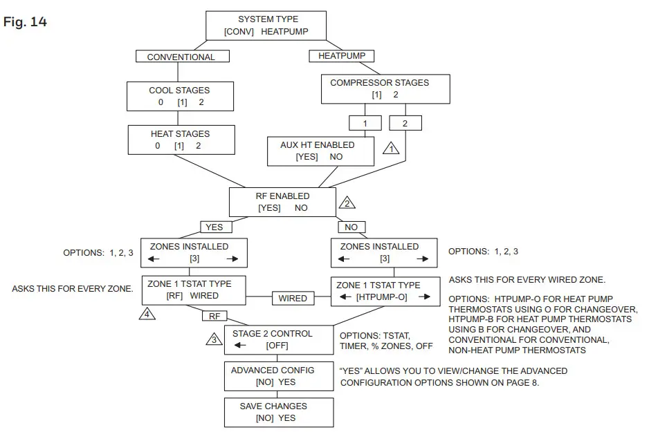 1. PANEL WILL NOT ASK IF YOU HAVE AUX HEAT WHEN 2 COMPRESSOR STAGES ARE SELECTED. THE HZ432 IS REQUIRED FOR A 3H/2C HEAT PUMP.
2. SET TO “YES” IF WIRELESS (RADIO FREQUENCY) THERMOSTATS AND THM4000R ADAPTER ARE USED.
3. SHOWN IF COMPRESSOR STAGES OR HEAT STAGES IS SET TO 2, OR AUX HT ENABLED IS SET TO “YES”
CONNECT WIRELESS DEVICES - RF MEANS “WIRELESS THERMOSTAT”
Press the Mode button until the Wireless LED lights up. The TrueZONE must be configured for wireless devices to select Wireless mode.
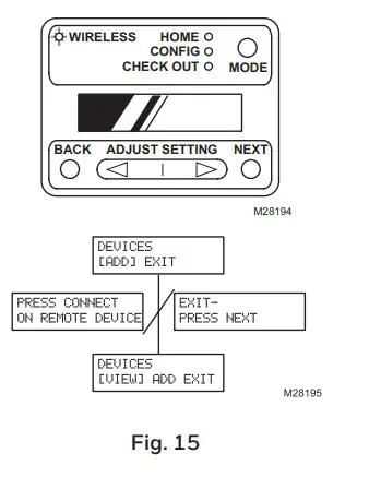 Press Next to add devices.
While the display alternates the Press Connect and Exit screens, push the Connect button(s) on the wireless device(s).
-OR
Follow the instructions that came with the wireless device(s). Press Next to exit.
ADVANCED CONFIGURATION
Use the Adjust Setting, Next, and Back buttons to configure the zone panel. See the Configuration section on page 7 for instructions on using these buttons.
Table 6. Advanced Configuration.
| Menu Name | Menu Title (LCD top line) | Menu Options (LCD bottom line; defaults in bold) | Menu option description | Notes: |
| Heat Fan | HEAT FAN
CONTROL |
[HVAC] PANEL | Fan control by HVAC | In heat mode, fan controlled by HVAC or
turned on by panel in call for heat. |
| HVAC [PANEL] | Fan control by Panel | |||
| Stage 2 Timer | STAGE 2 TIMER | [5 MIN] > – < [60 MIN]
[5 MIN] > |
5 minutes–60 minutes | A number of minutes to delay before engaging second stage. |
| Purge Timer | PURGE TIME | [2] 3.5 5 MIN | 2.0 minutes | A number of minutes panel will purge the following call for heat or cool. |
| 2 [3.5] 5 MIN | 3.5 minutes | |||
| 2 3.5 [5] MIN | 5.0 minutes | |||
| Purge Fan | FAN IN PURGE | [HVAC] PANEL | Fan control by HVAC | Fan controlled by HVAC or panel during the purge. |
| HVAC [PANEL] | Fan control by Panel | |||
| Purge Dampers | PURGE DAMPERS | [UNCHANGD] OPEN | Dampers Unchanged | Damper position unchanged or all dampers open during the purge. |
| UNCHANGED [OPEN] | Dampers All Open | |||
| Auto Changeover Delay | CHANGEOVER DELAY | [15] 20 30 MIN | 15 minutes auto changeover timer | A number of minutes to delay auto changeover when one zone is calling for heat and another is calling for cooling. |
| 15 [20] 30 MIN | 20 minutes auto changeover timer | |||
| 15 20 [30] MIN | 30 minutes auto changeover timer | |||
| DATS Enabled | DISCHARGE SENSOR | [NO] YES | Disabled | Enables or disables DATS. If Disabled, the Multistage DATS Inhibit setting is Disabled. |
| NO [YES] | Enabled | |||
| DATS High Limit | DAT HIGH LIMIT | [110 F] > – < [180 F] < [160 F] > |
110 deg F–180 deg F | For furnace systems, high limit should be set approximately 15 degrees below the furnace high limit setting. |
| DATS Low Limit | DAT LOW LIMIT | [30 F] > – < [60 F]
< [40 F] > |
30 deg F–60 deg F | Low-temperature limit. |
| OT Temp Enabled* | OT SENSOR | [NO] YES | Disabled | Enables or disables wireless outdoor temperature sensors. If Disabled, the Multistage OT Temp Lockout setting is Disabled. |
| NO [YES] | Enabled | |||
| OT Trip Point for | OUR LOCKOUT | [0 F] > – < [50 F] | 0 deg F–50 deg F | Above this temperature 2nd stage heat is |
| Multistage Lockout | TEMP | < [50 F] > | locked out. | |
| Multistage DATS Inhibit | DAT MSTG INHIBIT | NO [YES] | Enabled | Allow panel to downstage multistage equip- ment when near DATS high or low limit. |
| [NO] YES | Disabled | |||
| LCD Contrast Adjust | LCD CONTRAST | [1] > – < [10] < [5]> |
Contrast value 1–10 | Sets LCD display contrast for ease of viewing. The lowest contrast is 1, highest contrast is 10. |
| Save Changes | SAVE CHANGES? | [NO] YES | Disabled | Saves or rejects the configuration settings. |
| NO [YES] | Enabled |
OPERATION
The HZ322 TrueZONE panel contains an LED display that communicates system and zone status. The LEDs indicate the following information.
 Much of this information, as well as configuration information, is listed on the label on the inside of the HZ322 cover. For users who prefer French or Spanish labels, they are provided in form 69-2199FS. Cut them out and attach them to the inside of the HZ322 cover.
Table 7. LED Operation.
| LED | Description |
| HEAT 1 | Solid when in heat stage 1. Blinking when DATS high limit mode has been reached. |
| HEAT 2 | Solid when in heat stage 2. Blinking when stage 2 is locked out due to DATS or OT. |
| COOL 1 | Solid when in cool stage 1. Blinking when DATS low limit mode has been reached. |
| COOL 2 | Solid when in cool stage 2. Blinking when stage 2 locked out due to DATS. |
| PURGE | Solid when in the purge (at power-up and after a call for heat or cool). Blinking when the DATS sensor has failed, or the wires are shorted or open. Will blink for 3 minutes at power-up if DATS is not present. |
| FAN | Solid with a call for the fan. |
| EM HEAT | Solid when in emergency heat mode. This light does not indicate a call for heat. Emergency heat will only run when both HEAT and EM HEAT are lit. |
| ZONE 1, 2, 3 | Solid green when open or opening. Solid red when closed or closing. Blinking amber when the damper VA exceeds the specified zone VA or there is a damper or thermostat short circuit (circuit breaker trip). |
CHECKOUT
To enter Checkout, with the zone panel cover off, press the Mode button until the Check out LED lights up. Use the Adjust Setting and Next buttons to work through the checkout menu as listed below. See the Configuration section on page 7 for instructions on using these buttons.
Steps 3–10 cycle through heating and cooling stages and open and close dampers to verify proper operation of the equipment and dampers. These steps energize the equipment and damper terminals.
Steps 11–14 verify thermostat operation and correct wiring. This is done by making the thermostats call for heat or cool and viewing the active wires as displayed on the LCD screen. This is a useful way to troubleshoot which thermostat terminals are actually energized on each zone.
Table 8. Checkout.
| Checkout Step | Line 1 display | Line 2 Display | Notes: | |
| 1. | The display shows OT* | OUR SENSOR VAL | current OT temp (dynamic) | All zone dampers open, all other relays OFF. |
| 2. | The display shows DATS** | DAT SENSOR VAL | current DATS (dynamic) | |
| 3. | Heat stages test | TEST HEAT | [OFF] 1 2 | Heat turns on (fan also turns on if configured for the fan on in heat). |
| 4. | EM Heat stages test | TEST EMERG HEAT | [OFF] 1 2 | Emergency heat turns on (fan also turns on). |
| 5. | Cool stages test | TEST COOL | [OFF] 1 2 | Cooling turns on (fan also turns on). |
| 6. | Fan Test | TEST FAN | [OFF] ON | Fan cycles on and off. |
| 7. | Damper 1 test | TEST Z1 DAMPER | [OPEN] CLOSED | Cycles damper position with the fan on. |
| 8. | Damper 2 test | TEST Z2 DAMPER | [OPEN] CLOSED | Cycles damper position with the fan on. |
| 9. | Damper 3 test | TEST Z3 DAMPER | [OPEN] CLOSED | Cycles damper position with the fan on. |
| 10. | View Tstat1 inputs | ZONE1 STAT INPTS | Displays active Tstat1 terminals or displays wireless thermostat operation | Tests thermostat wiring with HVAC off. |
| 11. | View Tstat2 inputs | ZONE2 STAT INPTS | Displays active Tstat2 terminals or displays wireless thermostat operation | Tests thermostat wiring with HVAC off. |
| 12. | View Tstat3 inputs | ZONE3 STAT INPTS | Displays active Tstat3 terminals or displays wire-less thermostat operation | Tests thermostat wiring with HVAC off. |
| 13. | Exit checkout mode? | EXIT CHECKOUT? | (NEXT = EXIT) | |
* Wireless outdoor Sensor C7089R and Wireless Adapter THM4000R required for OT Temperature.
**Discharge Air Temperature Sensor C7735A required to display Discharge Air Temperature.
WARRANTY
Resideo warrants this product, excluding battery, to be free from defects in workmanship or materials, under normal use and service, for a period of five (5) years from the date of first purchase by the original purchaser. If at any time during the warranty period the product is determined to be defective due to workmanship or materials, Resideo shall repair or replace it (at Resideo’s option).
If the product is defective,
- return it, with a bill of sale or other dated proof of purchase, to the place from which you purchased it; or
- call Resideo Customer Care at 1-800-828-8367. Customer Care will make the determination whether the product should be returned to the following address:
Resideo Return Goods, 1985 Douglas Dr. N., Golden Valley, MN 55422, or whether a replacement product can be sent to you.
This warranty does not cover removal or reinstallation costs. This warranty shall not apply if it is shown by Resideo that the defect was caused by damage that occurred while the product was in the possession of a consumer.
Resideo’s sole responsibility shall be to repair or replace the product within the terms stated above. RESIDE SHALL NOT BE LIABLE FOR ANY LOSS OR DAMAGE OF ANY KIND, INCLUDING ANY INCIDENTAL OR CONSEQUENTIAL DAMAGES RESULTING, DIRECTLY OR INDIRECTLY, FROM ANY BREACH OF ANY WARRANTY,
EXPRESS OR IMPLIED, OR ANY OTHER FAILURE OF THIS PRODUCT.
Some states do not allow the exclusion or limitation of incidental or consequential damages, so this limitation may not apply to you.
THIS WARRANTY IS THE ONLY EXPRESS WARRANTY RESIDE MAKES ON THIS PRODUCT. THE DURATION OF ANY IMPLIED WARRANTIES, INCLUDING THE WARRANTIES OF MERCHANTABILITY AND FITNESS FOR A PARTICULAR PURPOSE, IS HEREBY LIMITED TO THE FIVE-YEAR DURATION OF THIS WARRANTY. Some states do not allow limitations on how long an implied warranty lasts, so the above limitation may not apply to you.
This warranty gives you specific legal rights, and you may have other rights which vary from state to state. If you have any questions concerning this warranty, please write Resideo Customer Care, 1985 Douglas Dr, Golden Valley, MN 55422 or call 1- 800-828-8367.
![]() www.resideo.com
www.resideo.com
Resideo Technologies, Inc.
1985 Douglas Drive North, Golden Valley, MN 55422 1-800-633-3991
69-2199—11 M.S. Rev. 03-20 | Printed in the United States
© 2020 Resideo Technologies, Inc. All rights reserved.
The Honeywell Home trademark is used under license from Honeywell International, Inc.
This product is manufactured by Resideo Technologies, Inc. and its affiliates.
Honeywell Home VTL15 Thermostatic Radiator Valves
Cautions:
- 2 – 130°C (36 – 266°F) Max. 10bar (145 psi) KVS = 0.70 m3/h Head connection M30x1.5
- For reliable and quiet operation: pmax = 1.0bar for Copper pipes only
- Reverse Flow TRVs
- Valve body approved for Keymark (EN215)
MODELS

Installing the thermostatic valve and head
- Fit tailpiece into radiator using PTFE Tape.
- Cut pipe cleanly and fir TRV body to radiator.
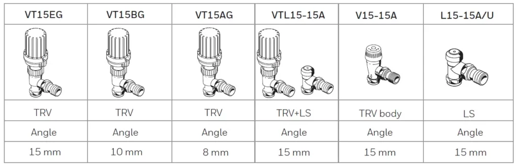
- Repeat for Lock shield.
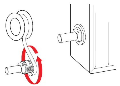
- Turn head to 5
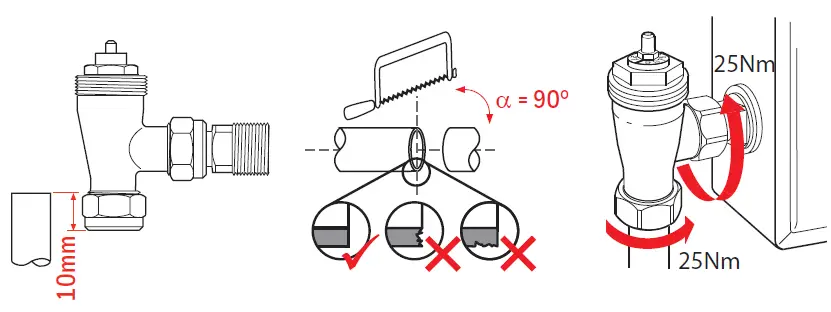
- Fit the TRV head and tighten onto the valve.
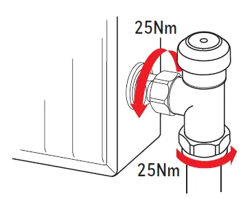
- Drain-off tailpieces can be ordered separately as VA15-DO/B (bulk pack of 15 pcs)
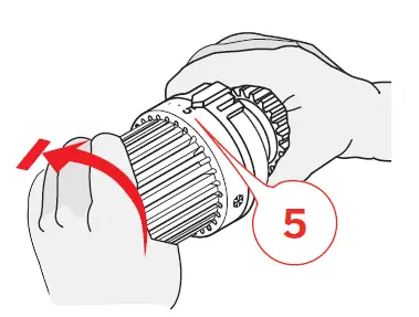
Integrate Balancing Insert
VT15/VTL15 TRVs can be balanced using either the Integrated Balancing Insert or the Lockschield Valve. Learn how to balance using the Integrated Balancing Instert at homecomfort.resideo.com/TRV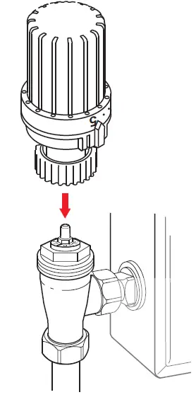
Setting temperature range limits on the thermostatic head
The TRV limits are set by using the ‘clip on’ tool to push one or both of two metal pins in the lower part of the head up into the top part of the head. They are removed by pushing them back again.
Example : Maximum at setting 4, minimum at setting 2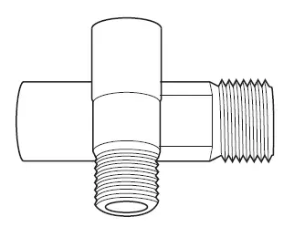
What is a thermostatic radiator valve (TRV)
Thermostatic Radiator Valves sense the air temperature around them and control the flow of water through the radiator which they are fitted to.
- TRV limt the temperature whithin each room and do not directly control the boiler, the boiler is switched by other controls such as Timers, Programmers, etc
- Turning a TRV to a higher setting will not make the room heat up any faster because this depends upon the boiler size and setting and the radiator size.
- UK Building regulations recommend a TRV to be fitted in each room except the one with the Room Thermostat.
- To save energy, turn each TRV only to a setting which is appropriate to its use.
- TRVs need a free flow of air to sense the temperature, so they must not be converted by curtains or blocked by furniture.
- For a clear understanding of your heat controls and how they work, ask your installer or visit the Homeowner section of heatingcontrols.honeywellhome.com
How to use
- Set the TRV to a setting corresponding to a temperature appropriate for the room.
- Turning the head to a higher setting may result in waste of energy without shortening the time to heat up the room. Oversupply of heating water brings only a negligible increase of the heat coming from the radiator.
- Turn the head to the antifreeze protection setting when you open a window.
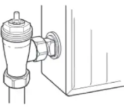
For more information
homecomfort.resideo.com/europe
Manufactured for and on behalf of the Pittway Sàrl, La Pièce 4, 1180 Rolle, Switzerland by its Authorised Representative Ademco 1 GmbH
MU2H-2123GE25 R0121
Subject to change
© 2021 Pittway Sàrl. All rights reserved. This document contains proprietary information of Pittway Sàrl and its affiliated companies and is protected by copyright and other international laws. Reproduction or improper use without specific written authorisation of Pittway Sàrl is strictly forbidden. The Honeywell Home trademark is used under license from Honeywell International Inc.
UK Head Office
Ademco 1 Limited
200 Berkshire Place
Winnersh Triangle
RG41 5RD Berkshire heatingcontrols.honeywellhome.com![]()
Honeywell Home THP9045A1098 C Wire Adapter

Online Guides
honeywellhome.com
Overview
This product replaces the need for a C-wire (common wire) to power a thermostat.
Only install if you do not have a C-wire available to connect to your thermostat.
BEFORE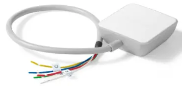 AFTER
AFTER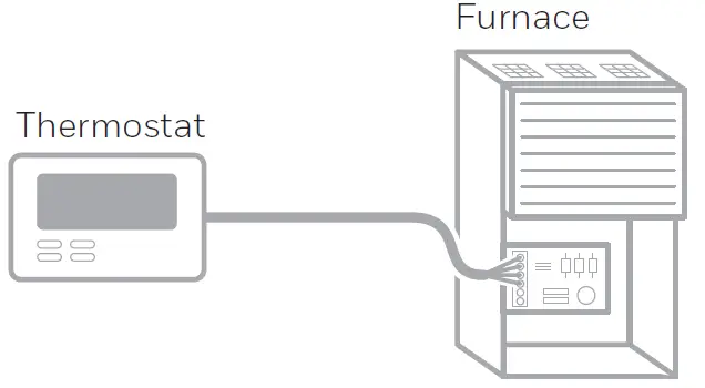 Compatibility Check
Confirm you have a G and Y wire
Look at your wires. Do you have BOTH a G and Y wire labeled?
YES – This means your system is compatible. Proceed to Step 2.
NO – Your system is not compatible with the C-Wire Adapter. Call 1-855-733-5465 to find a pro-installer.
Relabel your G wire to be C
Use the provided labels.
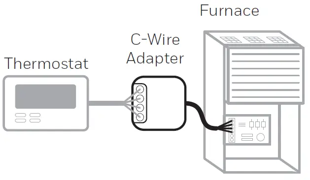
Relabel your Y wire to be K
Use the provided labels.
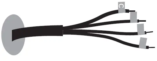
Go to your furnace or heating system
This system is often located in your basement, attic, or garage. Bring labels, flashlight, screwdriver and phone.
Remove cover of furnace or heating system
Open the furnace or heating system’s cover to find the control board.
Note: You may need to unscrew the cover (top or bottom).
Leave the power off.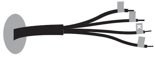
Locate the bundle of wires that are the same as the ones at your thermostat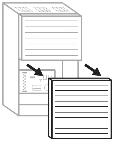
Take a picture of the wiring
Take multiple pictures from different angles to capture all of the letters next to the terminals.
G
C
R
W or W1 (not in all systems)
Y or Y1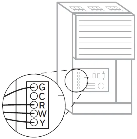
Be sure to include the terminal labels and wires. You may need to reference this image later.
Note: If you have wires connected to 2 R terminals, then you have a two-transformer system. Call 1-855-733-5465 to find a pro installer.
Label the wires
Use the provided stickers to label the wires connected to the following terminals:
G
R
W or W1 (not in all systems)
Y or Y1
Note: If multiple wires are connected to a terminal, only label the wires running to your thermostat.
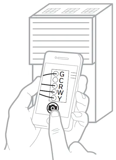
Disconnect the labeled wires
Be sure you have taken a photo of your wires before disconnecting.
Disconnect only the wires that you just labeled. Do not disconnect any unlabeled wires.
If unlabeled wires disconnect, replace immediately.
Note: You may need a screwdriver to release wires from terminals.
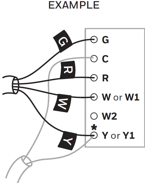
Connect wires to the C-Wire Adapter
Firmly depress the terminal tabs and insert the labeled wires into the “Thermostat” side of your C-Wire Adapter.
Insert the wires into their corresponding terminals as shown below.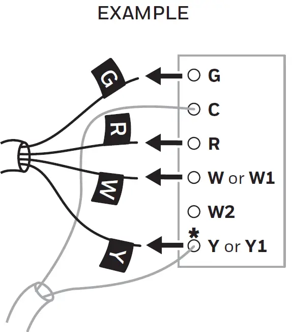
Ensure the wires are connected
Gently tug on the wires to be sure they are connected to the C-Wire Adapter.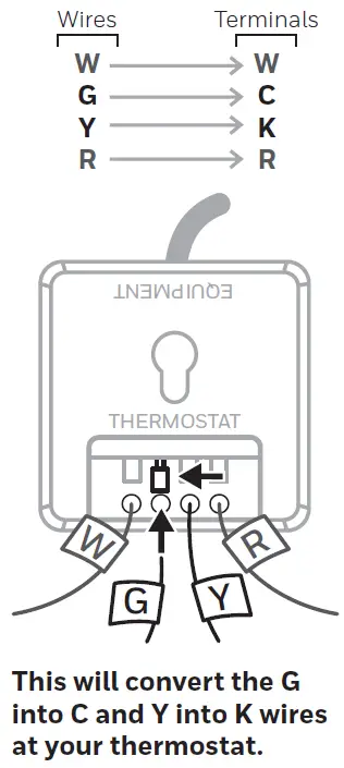
Connect wires to control board
Take the wires from the “Equipment” side of your C-Wire Adapter and connect them to the control board.
Be sure to remove the plastic tips and insert the wires into their corresponding terminals as shown below.
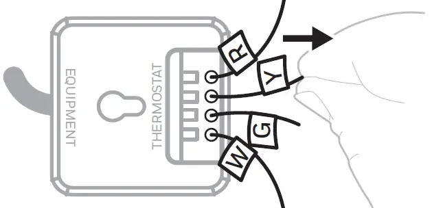
Mount C-Wire Adapter
Use the included mount and adhesive pad to mount the C-Wire Adapter inside your furnace or heating system.
Note: Make sure your wires are not over extended or strained.
a) Clean the surface
b) Firmly press the adhesive
c) Mount the C-Wire Adapter
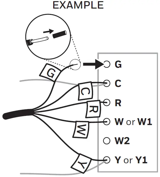
Mount anywhere inside the furnace.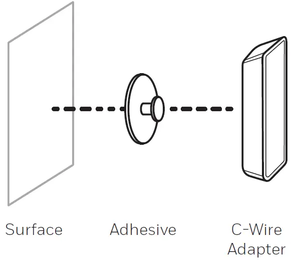
Close the cover to the furnace or heating system
Be sure the cover is completely closed. Some systems will not power up if the cover is not fully closed.
Leave the power off.
You’ve connected the C-Wire Adapter. Go back to the “Installing Your New Thermostat” section of the Installation Guide to complete the installation.
Electrical Specifications
INPUT: 24V~@60Hz, 0.2A
Resideo Technologies Inc.
1985 Douglas Drive North,
Golden Valley, MN 55422
1-800-468-1502
33-00422ES—03 M.S. Rev. 04-20 |
Printed in United States
© 2020 Resideo Technologies, Inc. All rights reserved.
The Honeywell Home trademark is used under license from Honeywell International, Inc. This product is manufactured by Resideo Technologies, Inc. and its affiliates.
![]()
Honeywell Home TH6320WF1005 FocusPro WiFi TH6000 Series Programmable Thermostat

This manual covers the following models
TH6320WF1005: For up to 3 Heat/2 Cool systems
System Types
- Gas, oil, or electric heat with air conditioning
- Warm air, hot water, high-efficiency furnaces, heat pumps, steam, gravity
- Heat only with fan
- Cool only
Must be installed by a trained, experienced technician
Read these instructions carefully. Failure to follow these instructions can damage the product or cause a hazardous condition.
Need Help?
For assistance with this product please visit http://customer.resideo.com or call Customer Care toll-free at 1-800-468-1502
Wallplate installation
- Separate wallplate from thermostat.
- Mount wallplate as shown below.
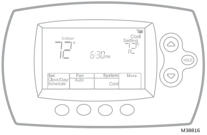
CAUTION: ELECTRICAL HAZARD
Can cause electrical shock or equipment damage. Disconnect power before beginning installation.
Wiring
Wiring guide — conventional systems
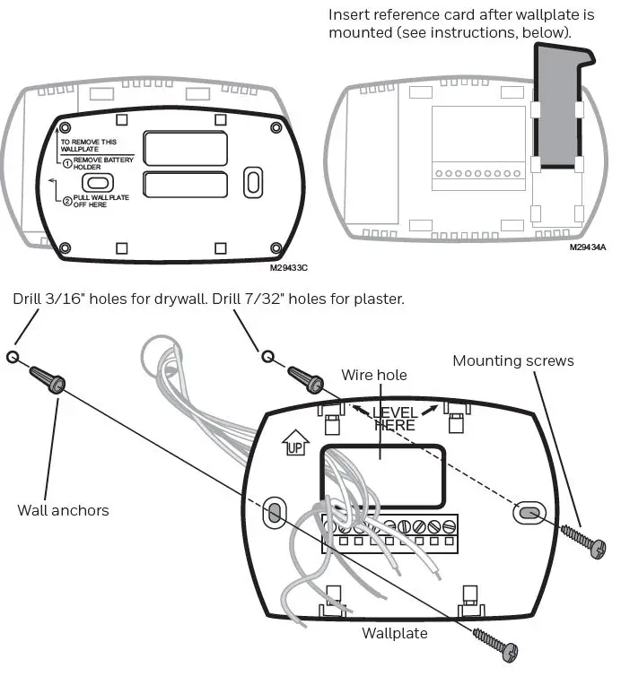
Wire specifications:
Use 18- to 22-gauge thermostat wire. Shielded cable is not required.
- Power supply. Provide disconnect means and overload protection as required.
- Remove jumper for 2-transformer systems.
- Common connection must come from cool-ing transformer.
- In Installer Setup, set system type to Heat Only.
- In Installer Setup, set system type to 2Heat/2Cool Conventional.
- In Installer Setup, set changeover valve to O or B.
- In Installer Setup, set system type to 2Heat/1Cool Heat Pump.
- In Installer Setup, set system type to 2Heat/2Cool Heat Pump.
- In Installer Setup, set system type to 3Heat/2Cool Heat Pump.
Wiring guide — heat pump systems
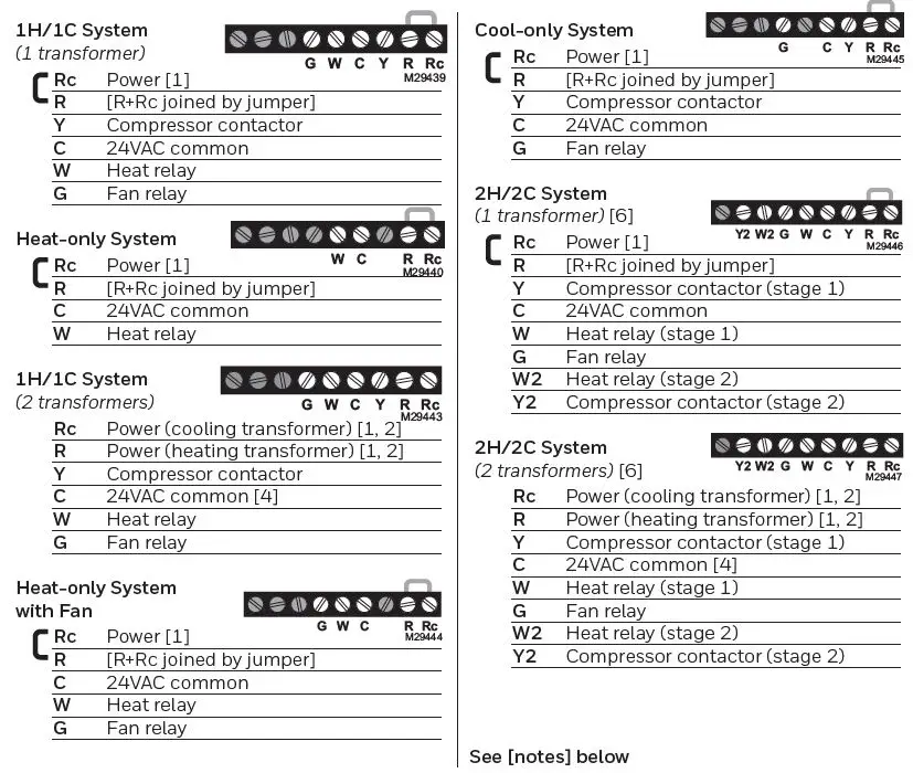
Wire specifications:
Use 18- to 22-gauge thermostat wire. Shielded cable is not required.
- Power supply. Provide disconnect means and overload protection as required.
- Remove jumper for 2-transformer systems.
- Common connection must come from cool-ing transformer.
- In Installer Setup, set system type to Heat Only.
- In Installer Setup, set system type to 2Heat/2Cool Conventional.
- In Installer Setup, set changeover valve to O or B.
- In Installer Setup, set system type to 2Heat/1Cool Heat Pump.
- In Installer Setup, set system type to 2Heat/2Cool Heat Pump.
- In Installer Setup, set system type to 3Heat/2Cool Heat Pump.

Terminal Designations
Conventional Terminal Letters:
- Y2 2nd stage compressor contactor.
- W2 2nd stage heat relay.
- K Optional wirer save module.
- Rc Cooling power. Connect to secondary side of cooling system transformer.
- R Heating power. Connect to secondary side of heating system transformer.
- W 1st stage heat relay.
- Y 1st stage compressor contactor.
- G Fan relay.
- C Common wire from secondary side of cooling transformer (if 2 transformers).
Heat Pump Terminal Letters:
- Y2 2nd stage compressor contactor. Aux/E Auxiliary/Emergency heat relay.
- K Optional wirer save module.
- Rc Cooling power. Connect to secondary side of cooling system transformer.
- R Heating power. Connect to secondary side of heating system transformer.
- O/B Changeover valve for heat pumps.
- Y 1st stage compressor contactor.
- G Fan relay.
- C Common wire from secondary side of cooling system transformer.
Installer setup
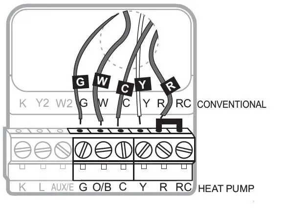
- Press Fan and s simultaneously and hold for approximately 3 seconds. The screen will change to display two numbers and the button designations will be Done, Back, blank, Next.
- Press Next until you see the function number—the larger number on the left—you want to set
- Change options for any function by pressing s or t until the correct option (smaller number on right) is displayed.
- Repeat Steps 2 and 3 until you have set all functions that you wish to change.
- When you have made all changes, press Done to save and exit
| 1 | Select System | 0 | Heat/cool: Gas, oil or electric heating with central air conditioning. |
| Type | 1
2 |
Heat pump: Heat pump without backup or auxiliary heat.
Heat only: Gas, oil or hot water heat without central air conditioning. |
|
| 3 | Heat only with fan: Gas, oil or electric heat without central air | ||
| conditioning. | |||
| 4 | Cool only: Central air conditioning only. | ||
| 5 | Heat pump: Heat pump with backup or auxiliary heating. | ||
| 6 | Heat/Cool Multiple stages: 2 heat stages, 2 cooling stages. | ||
| 7 | Heat/Cool Multiple stages: 2 heat stages, 1 cooling stage. | ||
| 8 | Heat/Cool Multiple stages: 1 heat stage, 2 cooling stages. | ||
| 9 | Heat Pump Multiple Stages: 2 heat stages, 2 cool stages. | ||
| 10 | Heat Pump Multiple Stages: 3 heat stages, 2 cool stages. | ||
| 2 | Heat Pump | 0
1 |
Cooling changeover valve: Use this setting if you connected a wire labeled “O” to the O/B terminal.
Heating changeover valve: Use this setting if you connected a wire labeled “B” to the O/B terminal. |
| Changeover Valve | |||
| (for heat pumps | |||
| only) | |||
| 3 | Heating Fan Control | 0
1 |
Gas or oil heat: Use this setting if you have a gas or oil heating system (system controls fan operation).
Electric heat: Use this setting if you have an electric heating system (thermostat controls fan operation). |
| 5 | Heating Cycle Rate | 5 Gas or oil furnace: Standard gas/oil furnace (less than 90% efficiency).
9 Electric furnace: Electric heating systems. 3 Hot water or high-efficiency furnace: Hot water system or gas furnace (more than 90% efficiency). 1 Gas/oil steam or gravity system: Steam or gravity heat systems. [Other options: 2,4,6,7,8,10,11,12] |
|
| 6 | Heating Cycle Rate Stage 2 | ||
| 7 | Heating Cycle Rate Auxiliary | ||
| 9 | 1st stage compres- sor cycle rate | 3 | Recommended for most compressors [Other options: 1, 2, 4, 5 or 6 CPH] |
| 10 | 2nd stage com- pressor cycle rate | ||
| 12 | Manual/Auto Changeover | 0
1 |
Manual changeover (Heat/Cool/Off).
Automatic changeover (Heat/Cool/Auto/Off). Automatically turns on Heat or Cool based on room temperature. Note: System maintains minimum 3°F difference between heat and cool settings. |
System setup
| 13 Adaptive Intelligent Recovery (AIR) | 1
0 |
On Off | ||||
| 14 | Temperature Format (°F/°C) | 0
1 |
Fahrenheit Celsius | |||
| 15 | Compressor protection | 5 5 minute compressor off time
[Other options: 0, 1, 2, 3 or 4-minute off time] |
||||
| 16 | Schedule Options | 1 Program schedule is on (7-day programmable).
0 Program schedule is off. Thermostat can not be programmed. |
||||
| 26 | Auxiliary Control | 0
1 |
Comfort Economy | |||
| 27 | Heat temperature range stop | 90 Max. heat temperature setting is 90°F (32°C) [Other options: 40-89°F (4°C to 32°C)] | ||||
| 28 | Cool temperature range stop | 50 Min. cool temperature setting is 50°F (10°C) [Other options: 51-99°F (11°C to 37°C)] | ||||
| 32 | Temperature display offset | 0 Thermostat displays actual room temperature
[Other options: -3, -2, -1, 1, 2, 3°F offset (-1.5°C to 1.5°C)] |
||||
| 36 | Device Name | 52 = Thermostat | ||||
| This name will identify the thermostat when you view it remotely.
If you register multiple thermostats, give each one a different name. |
1 Basement
2 Bathroom 3 Bathroom 1 4 Bathroom 2 5 Bathroom 3 6 Bedroom 7 Bedroom 1 8 Bedroom 2 9 Bedroom 3 10 Bedroom 4 11 Boat House 12 Bonus Room 13 Computer Room 14 Den 15 Dining Room |
16 Exercise Room
17 Family Room 18 Fireplace 19 Foyer 20 Game Room 21 Garage 22 Great Room 23 Guest Room 24 Gym 25 Kid’s Room 26 Kitchen 27 Kitchen 1 28 Kitchen 2 29 Laundry Room |
30 Library
31 Living Room 32 Lower Level 33 Master Bath 34 Master Bed 35 Media Room 36 Music Room 37 Nursery 38 Office 39 Office 1 40 Office 2 41 Pantry 42 Play Room 43 Pool Room |
44 Porch
45 Rec Room 46 Sewing Room 47 Spa 48 Storage Room 49 Studio 50 Sun Room 51 Theater 52 Thermostat 53 Upper Level 54 Utility Room 55 Walk In Closet 56 Wine Cellar 57 Workshop |
||
| 38 | Wi-Fi On/Off | 1 Wi-Fi is on and can be connected to a Wi-Fi network.
0 Wi-Fi is off. Thermostat cannot be connected to a Wi-Fi network. If you are not connecting the thermostat to a Wi-Fi network this will remove the text Wi-Fi Setup from the messaging center. |
||||
| 39 | Wi-Fi Connection | 1 Connected to Wi-Fi network. This is set automatically when the thermostat is connected to the Wi-Fi network.
0 Set to 0 to disconnect from the Wi-Fi network. |
||||
| 42 | Show period and day of week | 0 Period and day are not shown on the home screen.
1 Period and day are shown on the home screen. |
||||
| 85 | Restore Schedule Defaults | 0 Continue using programmed schedule.
1 Restore thermostat program to energy saving settings |
||||
| 90 | Restore Original Settings | 0 No
1 Disconnects thermostat from Wi-Fi and restores original settings (erases customizations). |
||||
Installer system test
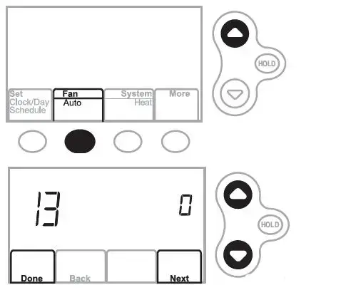
| 10 | Heating system | 0 | Heat and fan turn off. |
| 1 | Stage 1 heat turns on. Fan turns on if Setup Function 1 is set to 1, | ||
| 5, 9 or 10 OR Setup Function 3 is set to 1 **See page 6 | |||
| 2 | Stage 2 heat turns on | ||
| 3 | Stage 3 heat turns on | ||
| 20 | Emergency heating | 0 | Heat and fan turn off |
| system | 1 | Heat and fan turn on | |
| 30 | Cooling system | 0 | Compressor and fan turn off |
| 1 | Compressor and fan turn on | ||
| 2 | Stage 2 compressor turns on | ||
| 40 | Fan system | 0 | Fan turns off |
| 1 | Fan turns on |
CAUTION: Compressor protection is bypassed during testing. To prevent equipment damage, avoid cycling the compressor quickly.
Troubleshooting
Lost Signal
If the no-Wi-Fi indicator displays in place of the Wi-Fi strength indicator in the upper right hand corner of the home screen:
- Check another device to be sure Wi-Fi is working in your home; if not, call your Internet Service Provider.
- Move the router.
- Restart the thermostat: remove it from the wallplate, wait 10 seconds, and snap it back onto the wallplate. Return to Step 1 of Connecting to your Wi-Fi network.
Error Codes
For certain problems, the thermostat screen will display a code that identifies the trouble. Initially, error codes are displayed alone in the time area of the screen; after a few minutes, the home screen is displayed and the code alternates with the time.
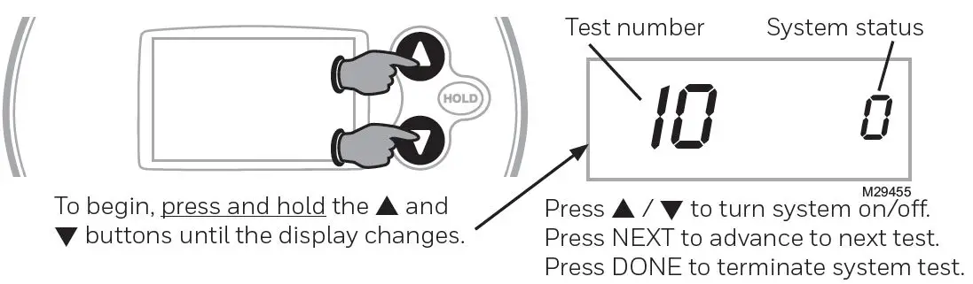
| E01 | During Wi-Fi Setup, the router lost power. | • Ensure your router has power.
• If trying to connect to a hidden or manually added network, confirm the router has power and is working. |
|
| E02 Invalid Wi-Fi password. This code displays for 30 seconds, then the thermostat will re- enter Wi-Fi Setup mode. | • Re-enter password for your home Wi-Fi network.
• Repeat setup process and confirm your password for your home Wi-Fi network. |
||
| E42 Router is not issuing an IP ad- dress to the thermostat. | • Wait for 30 minutes, connection can take several minutes.
• If still no connection, remove thermostat from wallplate for 10 seconds, then reconnect it. • Verify your router is correctly setup to automatically give IP addresses. |
M33998A | |
| E43 No internet connection. Ther- mostat cannot communicate to Total Connect Comfort. | • Make sure the Internet cable is plugged in.
• Reboot the router. |
||
| E99 | General error | Remove thermostat from wallplate for 10 seconds, then recon- nect it. | |
If you have difficulty with your thermostat, please try the following suggestions. Most problems can be corrected quickly and easily.
Display is blank
- Check circuit breaker and reset if necessary.
- Make sure power switch at heating and cooling system is on.
- Make sure furnace door is closed securely.
- Make sure C wire is connected.
Fan does not turn on when heat is required
Check Function 3: Heating Fan Control to make sure it is set to match the heating equipment
Cool On or Heat On is flashing on the screen
Compressor protection feature is engaged. Wait 5 minutes for the system to restart safely, without damage to the compressor.
Heat pump issues cool air in heat mode, or warm air in cool mode
Check Function 2: Heat Pump Changeover Valve to make sure it is properly configured for your system.
Heating system is running in cool mode
Check Function 1: System Type to make sure it is set to match the heating and cooling equipment
Heating and cooling equipment are running at the same time
- Check Function 1: System Type to make sure it is set to match the heating and cooling equipment.
- Grasp and pull thermostat away from wallplate. Check to make sure bare wires are not touching each other.
- Check thermostat wiring is correct
Special functions
Auto Changeover (Setup Function 12): When set to Auto, the thermostat automatically selects heating or cooling depending on the indoor temperature. The thermostat will automatically adjust heat and cool settings to maintain a 3-degree separation (fixed). Note: If you select Auto Changeover Only, the System Setting on the thermostat will stay locked in the Auto position, preventing the user from changing it to Em Heat, Heat, Cool or Off.
Adaptive Intelligent Recovery™ (Setup Function 13): Allows the thermostat to “learn” how long the furnace and air conditioner take to reach programmed temperature settings, so the temperature is reached at the scheduled time.
Compressor Protection (Setup Function 15): Forces the compressor to wait a few minutes before restarting, to prevent damage. During the wait time, the message Cool On or Heat On (heat pumps only) will flash on the display.
Accessories & replacement parts
Please contact your distributor to order replacement parts.
- Cover plate assembly Part Number 50002883-00112
- pack of medium cover plates Part Number 50007298-001
Specifications
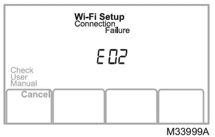
MERCURY NOTICE
If this product is replacing a control that contains mercury in a sealed tube, do not place the old control in the trash. Contact your local waste management authority for instructions regarding recycling and proper disposal.
CAUTION: ELECTRONIC WASTE NOTICE
The product should not be disposed of with other household waste. Check for the nearest authorized collection centers or authorized recyclers. The correct disposal of end-of-life equipment will help prevent negative consequences for the environment and human health.
Resideo Technologies, Inc. 1985 Douglas Drive North, Golden Valley, MN 55422 1-800-468-1502 69-2738EFS—05 M.S. Rev. 02-22 | Printed in United States www.resideo.com
© 2022 Resideo Technologies, Inc. All rights reserved. The Honeywell Home trademark is used under license from Honeywell International, Inc. This product is manufactured by Resideo Technologies, Inc. and its affiliates.
]]>Honeywell Home ST699 Electronic Dual Zone Timer

PRODUCT DATA
The ST699 electronic dual zone timer is used to control gravity, primary or fully pumped central heating systems requiring a single 24 hour programme with two ON/OFF periods per day. ST699 incorporates a simple and intuitive programming concept which established its predecessor as the leading electronic dual zone timer on the market. ST699 is designed for European CEN approval.
FEATURES
- 24-hour programme
- Independent heating and hot water channels
- One or Two ON/OFF periods per day
- Built-in programme
- Temporary programme override/advance
- 7-day battery back-up
- Compact size
- AM/PM or 24 hour clock format (factory option) Wallplate compatibility with 7-day version (ST799)
- 10 minute programme resolution
- 3 A resistive/inductive (@ 0.6 pf) 230 V~ SPDT relay rating
- Simple/intuitive programming
- Surface or wallbox mounting options
- Pack contains everything for immediate installation
SPECIFICATIONS
Product type: Electronic dual zone timer Power supply : 230 V~ (±10%), 50 HZ
Power reserve: Rechargeable battery with 7 days backup following a 24 hour charging period
Switch rating: 2 x SPDT potential free 3 A resistive @ 230 V~ (± 10%), 50 Hz 3 A inductive @ 0.6 pf
Programme: 24-hour with two ON/OFF periods daily
Programme resolution: 10 minutes
Programme day: 03.00 AM to 02.50 AM (on the next day)
Override: Advance next programme time (change)
Wiring: Surface or single wallbox (UA1 size)
Wiring access: Rear or bottom edge (surface wiring access)
Wire gauge: 0.75 to 2.5 mm2 two max. per terminal Dimensions : 100 x 100 x 38 mm (w x h x d) Protection class : IP20 (IEC 529)
Environmental: Operating temperature range 0 to 45oC Shipping and storage temperature range -20 to 55oC Humidity range 0 to 90% rh, non-condensing
Approvals: Designed to meet European CEN approval EN60730
Life: 7 years minimum
DIMENSIONS
ORDERING SPECIFICATION
ST699B1002
INSTALLATION
Mounting
Remove the subbase from the timer by depressing the securing clip A and pulling the two halves apart. See fig. 1 The ST699 can either be mounted onto the wall surface or a flush mounted UA1 (with 60.3 mm pitch mounting holes) using the screws supplied.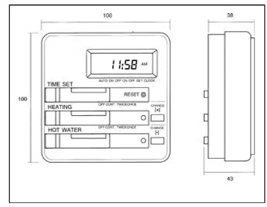
IMPORTANT
- The installer must be a trained service engineer
- Disconnect the power supply before beginning installation.
WIRING
Cable entries can be made through the opening in the rear of the subbase, or via the three surface entry break-outs in the top and two sides of the wallplate. See fig. 2 The ST699 is designed for fixed wiring only and must be wired in accordance with the latest IEE wiring regulations. Ensure the wiring connections to the mains supply is via a fuse rated at not more than 3 A and a Class “A” switch (having contact separation of at least 3 mm in all poles). Remove the terminal cover to allow access to the wiring terminals as shown in fig.2. Connect the systems wiring as shown by the specific applications wiring diagram. A maximum of two 2.5 mm2 (cross sectional area) wires can be connected to each terminal as shown in fig.3. Each wire should be stripped of insulation to a length no greater than 7mm to safeguard against the possibility of electrical shorts.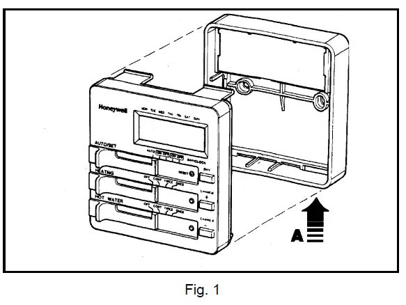
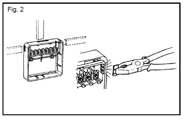
Systems Wiring
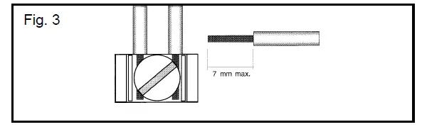
*A link must be provided between L-5-8 on the subbase of ST699 for all Sundial Plans, or fully controlled pumped primary systems.
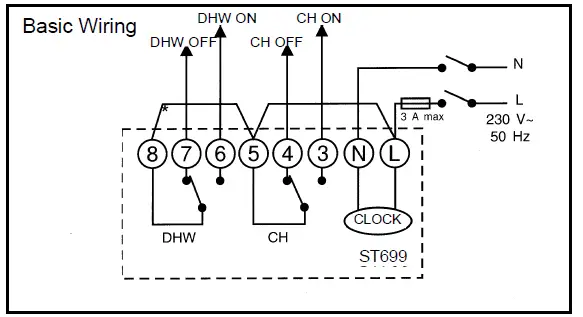
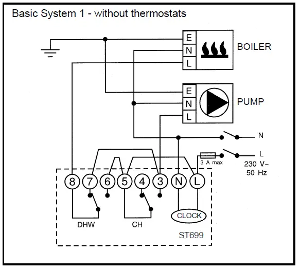
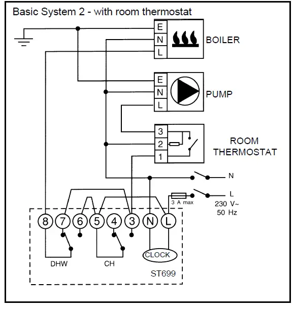
SUNDIAL PLAN WIRING DIAGRAMS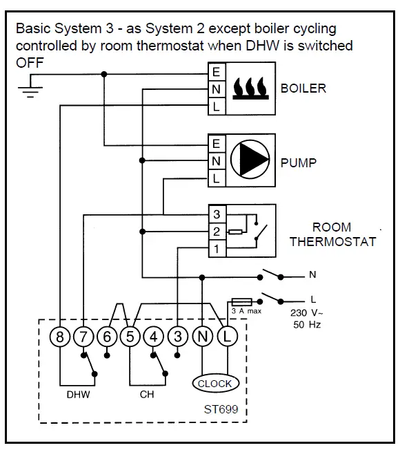
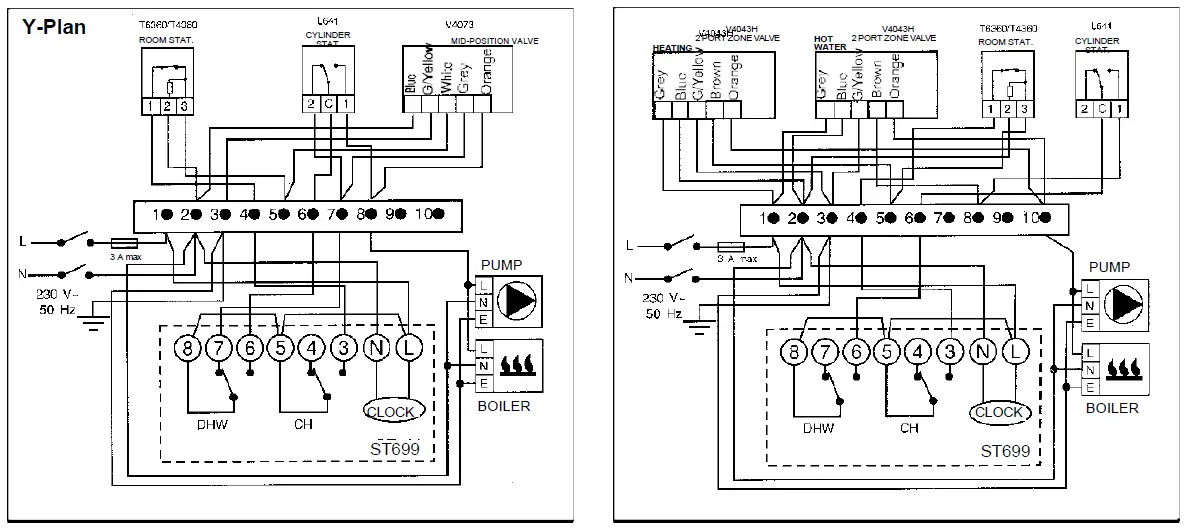
NOTE: In the Sundial S, W, and Y Plan wiring diagrams, connections are shown to basic boilers only. For wiring connections to pump overrun boilers refer to boiler manufacturers instructions or Honeywell Home for assistance.
Final Assembly
When the wiring is completed, replace the terminal cover ensuring it is correctly installed with ends located under the tabs and the locking pin through the locating hole. Replace the timer onto the wall plate, ensuring it is firmly secured by the three securing clips. Switch on the power and refer to the user’s guide for programming details. If the display remains blank, press the RESET button with a blunt object. (e.g. a pencil)
Ademco 1 GmbH
Hardhofweg 40
74821 Mosbach
Phone: +49 1801 466 388
[email protected]
homecomfort.resideo
@2020 Resideo Technologies, Inc. All rights reserved The Honeywell Home trademark is used under license from Honeywell International Inc. This product is manufactured by Resideo Technologies, Inc and its affiliates.![]()
User Manual
TF228WN Digital Thermostat
Quick Start Guide
Thermostat Appearance

Operating Your Thermostat
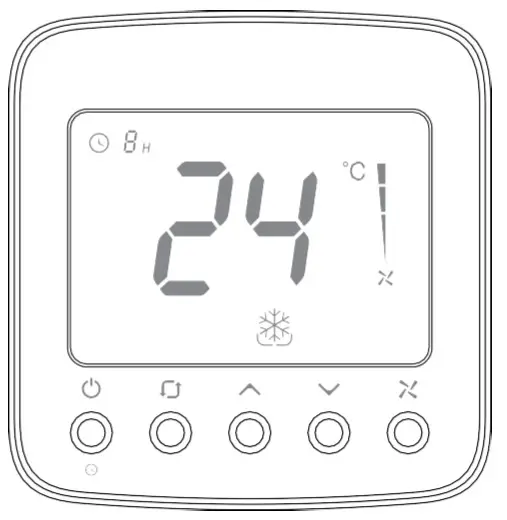
LCD Display
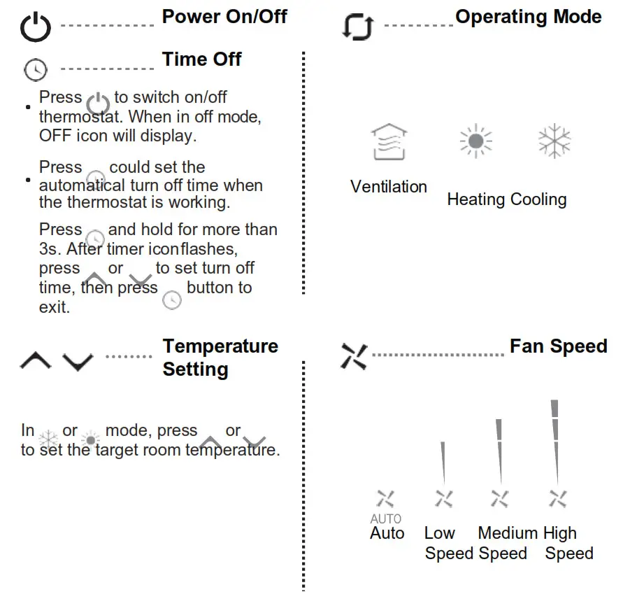
Trouble Shooting Tips
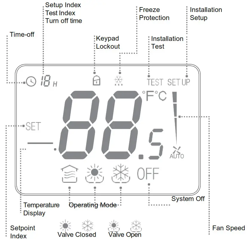
Installation Guide
Must be installed by a trained and experienced installer
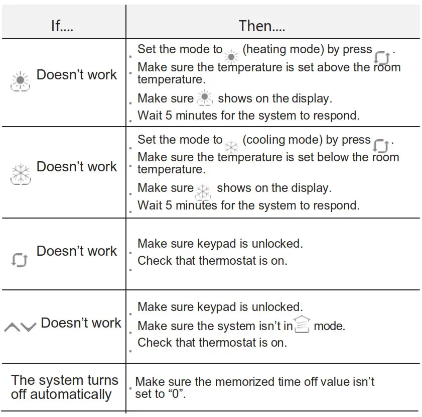 Read instruction carefully. Failure to follow instruction will damage the product or cause a hazardous condition.
Caution: ELECTRICAL HAZARD can cause electrical shock or equipment damage. Disconnect power before installation, reparation and detachment.
Installation Tips
TF228WN is designed for standard 75x75x5mm wall mounting box installation.Install the thermostat about 5 feet (1.5m) above the floor in an area with good air circulation at average temperature.

Do not install in locations where the thermostat can be affected by:
- Dead spots behind doors and in corners
- Hot or cold air from ducts
- Sunlight or radiant heat from appliances
- Concealed pipes or chimneys
Terminal Designations
| Terminal | Description |
| L | 220VAC live wire |
| N | 220VAC neutral wire |
| VC | Heating / Cooling valve close |
| VO | Heating / Cooling valve open |
| FH | High speed fan |
| FM | Medium speed fan |
| FL | Low speed fan |
* The temperature of mounting box and wall should be in the operating temperature range.
Wiring Diagram 1
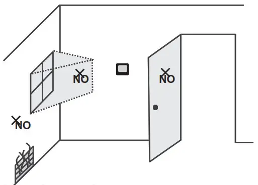
Wiring Diagram 2
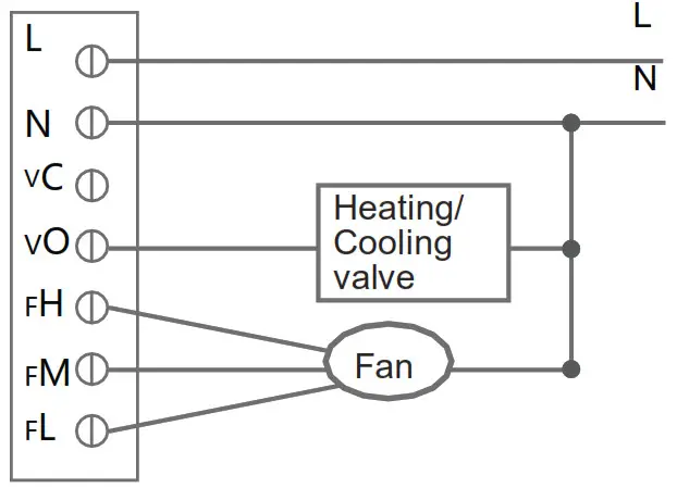
Wiring and Installation
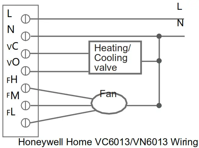 The screw must be locked tightly to avoid wire break off from the terminal.

Installation Setup
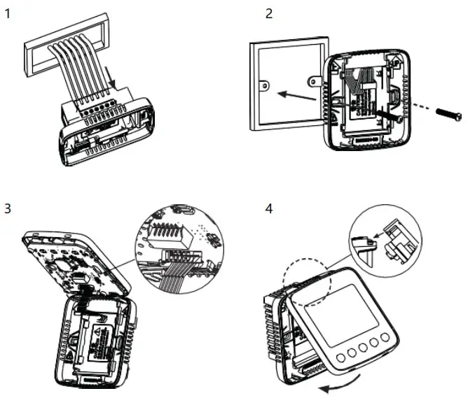
ISU Code |
Description |
Possible Options |
| 1 | System Type | 0 Heat only |
| 1 Cool only | ||
| 2 Two pipes heating/cooling(Default) | ||
| 2 | Temperature Scale | 0 °F |
| 1 °C (Default) | ||
| 3 | Fan Control Type | 0 Auto only |
| 1 Constant only | ||
| 2 Both(Default) | ||
| 4 | CPH Value (heating) | 1-12 4(Default) |
| 5 | CPH Value (cooling) | 1-6 3(Default) |
| ISU Coded |
Description |
Possible Options |
| 6 | Temperature Display Adjustment | -2 °C- 2 °C, 0.5 °C, Default 0 °C (-4 °F- 4 °F, 1 °F, Default 0 °F) |
| 7 | Temperature Display Options | 0 Display room temperature (Default) |
| 1 Display set point | ||
| 8 | Heating Range Stop | 10-32 °C Default 32 °C (50-90 °F Default 90 °F ) |
| 9 | Cooling Range Stop | 10-32 °C Default 10 °C (50-90 °F Default 50 °F) |
| 10 | Keypad Lockout | 0 All keys are available(Default) |
| 1 System button is locked | ||
| 2 Fan and System button are locked | ||
| 3 All buttons are locked except power button | ||
| 4 All buttons are locked | ||
| 11 | Freeze Protection | 0 Disabled (Default) |
| 1 Enabled |
 www.resideo.com
Ademco 1 GmbH
Hardhofweg 40
74821 Mosbach
Phone: +49 1801 466 388
[email protected]
homecomfort.resideo.com
@2020 Resideo Technologies, Inc. All rights reserved. The Honeywell Home trademark is used under license from Honeywell International Inc. This product is manufactured by Resideo Technologies, Inc and its affiliates.
