Honeywell C7835A1009 Discharge Air Temperature Sensor Installation Guide
APPLICATION
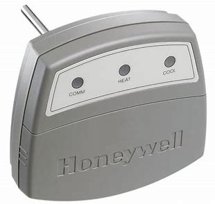
The C7835A1009 Discharge Air Temperature Sensor (DATS) is a duct-mounted temperature probe that provides capacity control of heating and cooling equipment. It is used only with Resideo networked zoning. Mounted in the supply air duct, the DATS senses the delivered air temperature and cuts off the heating or cooling when the delivered air temperature goes above or below normal operating limits.
The heating and cooling limits are field-adjustable.The DATS also compares the discharge air temperature to the room temperature and, if out of tolerance, a heating or cooling alert is issued. In normal operation,
the heat and cool lights are off, and the COM light blinks periodically with activity on the Enviracom bus.
When either limit setting is reached, the heating or cooling shuts off, and the LEDs operate according to
Table 1. The call still exists and heated or cooled air is still being supplied to the calling zones. Once the delivered air temperature drops ten degrees for heating, or rises ten degrees for cooling, the heating
or cooling equipment is brought back on. The ten degree differential provides adequate minimum timeoff to avoid damaging the equipment.
NOTE: When using 50 Hz power, cut Jumper W1.
The location of the DATS is critical; it should not be placed in line-of-sight of the heat exchanger or cooling coil because the DATS could activate prematurely. It should also be located before the
bypass damper, when applicable. See Fig. 1 for dimensions.
The DATS requires only three wires. Normal 18-22 gauge thermostat wire is used
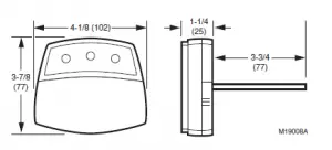
Fig. 1. C7835A dimensions in in. (mm).
When Installing this Product…
- Read these instructions carefully. Failure to follow them could damage the product or cause a hazardous condition.
- Check the ratings given in the instructions and on the product to make sure the product is suitable for your application.
- Installer must be a trained, experienced service technician.
- After completing installation, use these instructions to check out the product operation.
IMPORTANT
Do not locate the DATS probe in a duct near the heat exchanger or strip heat, which can cause false temperature readings.
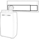
- Locate the DATS on the supply trunk between the bypass damper and the evaporator coil and/or heat exchanger. If a bypass damper is not used, locate the DATS between the zone dampers and the evaporator coil and/or heat exchanger. See Fig. 2.
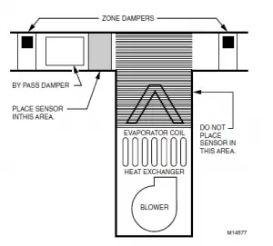
Fig. 2. DATS mounting location. - Drill a 5/16 in. hole in the duct at the location selected for the sensor.
NOTE: Be sure the shoulder washer is inserted, see Fig. 3, and fits tightly into the hole.
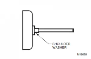
Fig. 3. Shoulder washer inserted on DATS - Remove the cover from the DATS case and insert the probe into the hole drilled in step 2.
- Secure the DATS to the side of the duct, through the two mounting holes in the back of the case, with the screws supplied.
- Connect the three DATS terminals, see Fig. 4, using standard thermostat wire, to any convenient Enviracom 1,2, and 3 terminal connection. Observe that the red heating and green cooling lights come on momentarily.
- Adjust the MAX Temp dial on the DATS to the appropriate high-limit setting. This can be set between 110°F and 160° F (43°C and 71°C).
Note that settings between the lines are approximate settings. The cooling low limit is adjustable between 40°F (4°C) and 48°F (9°C) based on the jumper position. - Replace the cover on the DATS case.
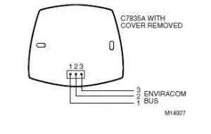
Fig. 4. DATS wiring to Enviracom™ bus.
TROUBLESHOOTING
Table 1. LED Operation.
| When DATS LED is… | It means… | It is corrected when… |
| Continuously red in heating. | Heating limit was exceeded. | Duct air temperature falls 10°F. |
| Continuously green in cooling. | Cooling limit was exceeded. | Duct air temperature rises 10°F. |
| Flashing red. | Heating system alert.a | Discharge air is within 10°F of room temperature continuously in heating mode. |
| Flashing green. | Cooling system alert.a | Discharge air is within 8°F of room temperature continuously in cooling mode. |
aHeating or cooling system alerts can be cleared by cycling power, switching modes from heat to cool or vice versa, or automatically when the equipment begins to operate correctly.
See Table 2 for resistance reading for each temperature to determine if the DATS is reading the correct temperature. To obtain a correct resistance measurement, remove the sensor probe P1 connector
from the circuit board. Measure resistance across the two sensor wires.
Table 2. DATS Resistance Cross Referencea.
| Temperature (°F) | Resistance | Temperature (°F) | Resistance |
| 32 | 33630 | 117 | 3915 |
| 33 | 32668 | 118 | 3830 |
| 34 | 31737 | 119 | 3747 |
| 35 | 30835 | 120 | 3666 |
| 36 | 29962 | 121 | 3587 |
| 37 | 29117 | 122 | 3510 |
| 38 | 28298 | 123 | 3435 |
| 39 | 27505 | 124 | 3362 |
| 40 | 26737 | 125 | 3290 |
| 41 | 25993 | 126 | 3221 |
| 42 | 25272 | 127 | 3153 |
| 43 | 24573 | 128 | 3086 |
| 44 | 23896 | 129 | 3021 |
| 45 | 23240 | 130 | 2958 |
| 46 | 22604 | 131 | 2896 |
| 47 | 21988 | 132 | 2836 |
| 48 | 21390 | 133 | 2777 |
| 49 | 20810 | 134 | 2720 |
| 50 | 20248 | 135 | 2664 |
| 51 | 19703 | 136 | 2609 |
| 52 | 19175 | 137 | 2555 |
| 53 | 18662 | 138 | 2503 |
| 54 | 18165 | 139 | 2452 |
| 55 | 17683 | 140 | 2402 |
| 56 | 17215 | 141 | 2353 |
| 57 | 16761 | 142 | 2306 |
| 58 | 16320 | 143 | 2259 |
| 59 | 15892 | 144 | 2214 |
| 60 | 15477 | 145 | 2170 |
| 61 | 15074 | 146 | 2126 |
| 62 | 14683 | 147 | 2084 |
| 63 | 14303 | 148 | 2043 |
| 64 | 13934 | 149 | 2002 |
| 65 | 13576 | 150 | 1963 |
| 66 | 13229 | 151 | 1924 |
| 67 | 12891 | 152 | 1886 |
| 68 | 12563 | 153 | 1849 |
| 69 | 12244 | 154 | 1813 |
| 70 | 11935 | 155 | 1778 |
| 71 | 11634 | 156 | 1744 |
| 72 | 11342 | 157 | 1710 |
| 73 | 11058 | 158 | 1677 |
| 74 | 10782 | 159 | 1645 |
| 75 | 10514 | 160 | 1613 |
| 76 | 10253 | 161 | 1582 |
| 77 | 10000 | 162 | 1552 |
| 78 | 9754 | 163 | 1523 |
| 79 | 9514 | 164 | 1494 |
| 80 | 9281 | 165 | 1466 |
Table 2. DATS Resistance Cross Referencea. (Continued)
| Temperature (°F) | Resistance | Temperature (°F) | Resistance |
| 81 | 9055 | 166 | 1438 |
| 82 | 8835 | 167 | 1411 |
| 83 | 8621 | 168 | 1385 |
| 84 | 8412 | 169 | 1359 |
| 85 | 8210 | 170 | 1334 |
| 86 | 8013 | 171 | 1309 |
| 87 | 7821 | 172 | 1285 |
| 88 | 7634 | 173 | 1261 |
| 89 | 7453 | 174 | 1238 |
| 90 | 7276 | 175 | 1215 |
| 91 | 7104 | 176 | 1193 |
| 92 | 6937 | 177 | 1171 |
| 93 | 6774 | 178 | 1150 |
| 94 | 6615 | 179 | 1129 |
| 95 | 6461 | 180 | 1108 |
| 96 | 6311 | 181 | 1088 |
| 97 | 6164 | 182 | 1069 |
| 98 | 6022 | 183 | 1050 |
| 99 | 5883 | 184 | 1031 |
| 100 | 5748 | 185 | 1012 |
| 101 | 5617 | 186 | 994 |
| 102 | 5488 | 187 | 977 |
| 103 | 5363 | 188 | 959 |
| 104 | 5242 | 189 | 943 |
| 105 | 5123 | 190 | 926 |
| 106 | 5008 | 191 | 910 |
| 107 | 4895 | 192 | 894 |
| 108 | 4786 | 193 | 878 |
| 109 | 4679 | 194 | 863 |
| 110 | 4575 | 195 | 848 |
| 111 | 4473 | 196 | 833 |
| 112 | 4374 | 197 | 819 |
| 113 | 4278 | 198 | 805 |
| 114 | 4183 | 199 | 791 |
| 115 | 4092 | 200 | 777 |
| 116 | 4002 | — | — |
aTo obtain a correct resistance measurement, be sure the sensor probe is disconnected from the circuit board.
For technical support, call 1-800-828-8367.
To download Zoning literature: www.resideo.com