
FocusPRO®5000 and 6000 Series Thermostats
INSTALLER SETUP AND SYSTEM TEST POCKET GUIDE
This is a legacy product document supported by Resideo. It is no longer manufactured

INSTALLER SETUP
FocusPRO®5000 Series
- To begin, press and hold the


- Press
- Press DONE to exit and save settings.
- Proceed to Installer Setup Functions on page 4.


FocusPRO ® 6000 Series
- To begin, press and hold the

- Press
- Press NEXT to advance to the next function.
- Press DONE to exit and save settings.
- Proceed to Installer Setup Functions on page 4.

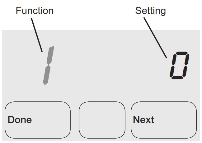
INSTALLER SETUP FUNCTIONS.
Available options and default settings vary by the thermostat.
| Table 1. Installer Setup | |||
| Setup functions | Setting & Options | ||
| (factory default in bold) | |||
| 1 | System type | 0 | 1 heat / 1 cool Cony. |
| 1 | 1 heat / 1 cool heat pump (no Aux. heat) | ||
| 2 | Heat only (2-wire, 3-wire zone valves [Series 20], and normally open zone valves) | ||
| 3 | Heat only with fan | ||
| 4 | Cool only | ||
| 5 | 2 heat / 1 cool heat pump (with Aux. heat) | ||
| 6 | 2 heat / 2 cool Corm | ||
| 7 | 2 heat / 1 cool Cony. | ||
| 8 | 1 heat / 2 cool Corm | ||
| 9 | 2 heat / 2 cool heat pump | ||
| (no Aux. heat) | |||
| 10 | 3 heat / 2 cool heat pump (with Aux. heat) | ||
| 2 | Changeover valve (0/B terminal) | 0 | Controls valve in cooling |
| 1 | Controls valve in heating | ||
| 3 | Fan control (heating) | 0 | Gas/Oil heat (equipment controls heating fan) |
| 1 | Electric furnace (thermo- stat controls heating fan) |
||
| 5 | First stage heat cycle rate | 5 | Gas or oil furnaces of less than 90%
efficiency |
| 1 | Steam or gravity | ||
| 3 | Hot water systems or fur- naces of 90%+ efficiency |
||
| 9 | Electric furnaces | ||
| [Other options: 1-12] | |||
| 6 | Second stage heat/Aux heat cycle rate | 5 | Gas or oil furnaces of less than 90% efficiency |
| 1 | Steam or gravity | ||
| 3 | Hot water systems or fur- naces of 90%+ efficiency |
||
| 9 | Electric furnaces | ||
| [Other options: 1-12] | |||
| 7 | Auxiliary heat cycle rate | 5 | Gas or oil furnaces of less than 90% efficiency |
| 1 | Steam or gravity | ||
| 3 | Hot water systems or fur- naces of 90%+ efficiency |
||
| 9 | Electric furnaces | ||
| [Other options: 1-12] | |||
| 8 | Emergency heat cycle rate | 9 | Electric emergency heat |
| 1 | Steam or gravity | ||
| 3 | Hot water systems or fur- naces of 90%+ efficiency |
||
| 5 | Gas or oil furnaces of less than 90% efficiency | ||
| [Other options: 1-12] | |||
| 9 | First stage compressor cycle rate | 3 | Recommended [Other options: 1-6] |
| 10 | Second stage compressor cycle rate | 3 | Recommended [Other options: 1-6] |
| 12 | Manual/Auto changeover | 0 | Manual changeover (Heat/Cool/Off) |
| 1 | Auto changeover (Heat/ | ||
| CooUAuto/Off) | |||
| 2 | Auto changeover only | ||
| (Auto) | |||
| 13 | Adaptive Intel- ligent Recovery” | 1 | On |
| 0 | Off | ||
| 14 | Temperature display | 0 | Fahrenheit |
| 1 | Celsius | ||
| 15 | Compressor protection | 5 | 5-minute compressor off time |
| [Other options: 0-4 minutes] | |||
| 16 | Schedule format I | 0 | 5/2 (weekdays and weekends |
| 1 | programmable) 5/1/1 (weekdays, | ||
| Saturday, and Sunday programmable) | |||
| 26 | Auxiliary heat control | 0 | Comfort |
| 1 | Economy | ||
| 27 | Heat temperature range stops | 90 | Max. heat temperature setting is 90°F (32°C) |
| [Other options: 40-89°F | |||
| (4.5°C to 32°C)] | |||
| 28 | Cool temperature range stop | 50 | Min. cool temperature setting is 50°F (10°C) |
| [Other options: 51-99°F | |||
| (10.5°C to 37°C)] |
INSTALLER SETUP TEST
Functions 13 and 16 are only available on the 6000 series; function 26 is only available on the 5000 series
FocusPRO ® 5000 Series
- To begin, press and hold the

- Presss
- Press DONE to terminate the system test.
- Proceed to Installer System Tests on page 8.


FocusPRO ® 6000 Series
- To begin, press and hold the and

- Press DONE to terminate the system test.
- Proceed to Installer System Tests on page 8.


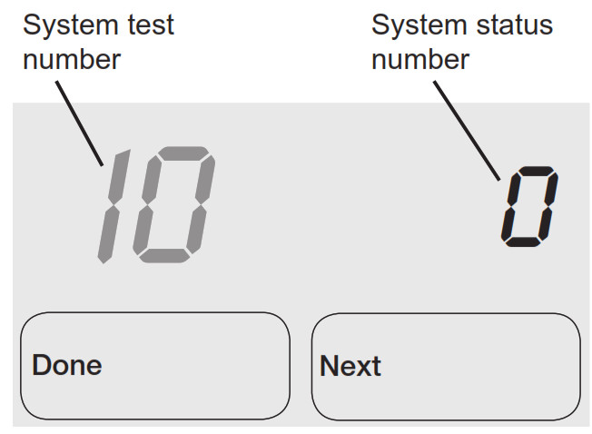
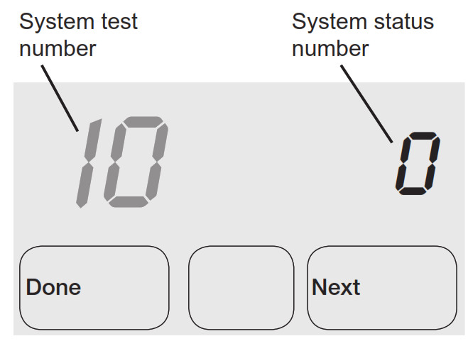
INSTALLER SETUP TESTS
Test the system’s heating, emergency heat, cooling, and fan. Available tests vary by thermostat and system type.
| Table 2. Installer System Test | ||
| System Test Number | Test Type | System Status Number and Description |
| 10 | Heating system | 0 Heat and fan off 1 First stage heat on (Fan turns on if Setup Function 1 is set to 1, 5, 9, or 10 OR setup Function 3 is set to 1) 2 Second stage heat on 3 Third stage heat on |
| 20 | Emergency heating system | 0 Heat and fan off 1 Heat and fan on 2 Second stage heat (Aux. heat) turns on |
| 30 | Cooling system | 0 Compressor and fan off 1 Compressor and fan on 2 Second stage compressor on |
| 40 | Fan system | 0 Off 1 On |
CAUTION
EQUIPMENT DAMAGE HAZARD.
Compressor protection is bypassed during testing. To prevent equipment damage, avoid cycling the compressor quickly.
![]()
Printed in the U.S.A. on recycled paper containing at least 10% post-consumer paper fibers. Automation and Control Solutions.
Honeywell International Inc. 1985 Douglas Drive North Golden Valley, MN 55422
Honeywell Limited- Honeywell Limitée 35 Dynamic Drive Toronto, Ontario M1V 4Z9 http://yourhome.honeywell.com
® the U.S. registered Trademark © 2006 Honeywell International Inc. US Patent No. 6595430, D509151; other Patents Pending. All Rights Reserved 69-2026 M.S. 09-06