![]()
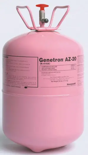
Honeywell Genetron® AZ-20
Properties, Uses,
Storage, and Handling
Introduction
Genetron® AZ-20® (an azeotropic mixture of HFC-32/HFC-125, assigned R-410A by ASHRAE), has been developed by Honeywell to serve as a long-term, non-ozone-depleting replace ment for HCFC-22 in a variety of new-equipment applications. Genetron AZ-20 has a significantly higher capacity and pressure than HCFC-22 and intrinsically low toxicity. Because it behaves like an azeotrope, Genetron AZ-20 is easy to service in the field.
Genetron AZ-20 is patented and has been recognized by Underwriters’ Laboratory as practically non-flammable.
Applications
Unitary Air Conditioning
Genetron AZ-20 is the ideal non-ozone-depleting, long-term replacement for HCFC-22 in new residential and light commercial unitary air conditioning systems. In new unitary systems optimized for its use, with either scroll or reciprocating compres sors, Genetron AZ-20 has shown in tests to have a 5-to-6 percent higher Energy Efficiency Rating (EER) than HCFC-22.
Genetron AZ-20 also has a higher capacity and pressure than HCFC-22, enabling the design of smaller, more compact air conditioning equipment.
Chillers
Genetron AZ-20 serves as an excellent replacement for HCFC-22 in new chillers, particularly positive displacement chillers. It also may serve as a retrofit fluid for replacing HCFC-22 in some existing chillers with components approved for high pressure, especially those with flooded heat exchangers. Honeywell recommends contacting the original chiller equipment manufacturer before carrying out any retrofit.
Commercial Refrigeration
Genetron AZ-20 may be used as a replacement for HCFC-22 in new medium-temperature commercial refrigeration systems, including supermarket display cases and reach-in coolers.
Servicing Considerations
Genetron AZ-20 is a 50/50 (wt. %) mixture of HFC-32/125.
Genetron AZ-20 exhibits azeotropic behavior with temperature glides that are less than 0.3°F (0.2°C) over the operating range.
When compared with azeotrope, an azeotropic mixture such as Genetron AZ-20 will not suffer significant segregation in a system and will not materially change its composition due to a leak. As a result, servicing a system that uses an azeotropic mixture is similar to servicing a system that uses a pure fluid.
Physical Properties
| Chemical Name | Difluoromethane/ Pentafluoroethane |
| Molecular Formula | CH2F2/CHF2CF3 |
| Appearance | Colorless |
| Molecular Weight | 73. |
| Boiling Point © 1 ATM (101.3 kPa) | -60.6°F -51.5°C |
| Freezing Point | -247°F -155°C |
| Critical Temperature’ | 160.444°F 71.358°C |
| Critical Pressure’ | 711.06 (Psia) 49.03 (bar) |
| Critical Volume’ | 0.0349 (ftilb) 0.0022 (m’/kg) |
| Critical Density’ | 28.69 (Ion 459.53 (kg/m³) |
| Vapor Density at Boiling Point | 0.26 (1b/ft’) 4.17 (kg/m³) |
| Liquid Density’ | 66.09 (1b/h’) 1059 (kg/m³) |
| Liquid Heat Capacity (at constant pressure) |
0.41 (Btu/lb°F) 1.71 (kJ/kg•K) |
| Vapor Heat Capacity’© 1 ATM | 0.17 (Btu/lb°F) 0.70 (kJ/kg•K) |
| Heat of Vaporization at Boiling Point ©1 ATM (101.3 kPa) | 117.43 (Btu/lb) 272.97 (kJ/kg) |
| Vapor Pressure’ | 239.59 (Psia) 16.52 (bar) |
| Liquid Thermal Conductivity’ | 0.0534 (Btu/hr ft°F) 0.0924 (W/m•K) |
| Vapor Thermal Conductivity’ | 0.0091 (Btuftir ft°F) 0.0157 (W/m•K) |
| Liquid Viscosity’ | 0.2825 (Ibm/ft hr) 116.73 (Ibm/ft hr) |
| Vapor Viscosity’ | 0.0351 (Ibm/ft hr) 14.50 (Ibm/ft hr) |
| % Volatiles by Volume | 100. |
| Solubility of Water in AZ-20 (wt. %) | 0.28 |
| Flammability Limits in Air (vol. %)’ | None |
| Ozone Depletion Potential (ODP) | 0.00 |
| ASHRAE Safety Group Classification | A1/A1 |
aRefprop v7.01 (NIST)
* ASTM E681-85 match ignition, ambient conditions
†All measurements are at 77° (25°C) unless otherwise noted.
Product Specifications
| Assay (Min. Wt % of HFC-32/125) | 99.70% |
| Moisture (Max. Wt. %) | 0.001 |
| Non-Volatile Residue (Max. Vol. %) | 0.01 |
| Chloride (Max. Wt. %) | 0.0001 |
| Total Acidity (Max. mg KOH/gm) | 0.0015 |
| Non-condensible in vapor phase (Max. Vol. %) | 1.5 |
Pressure vs. Temperature
| Temp. °F |
Pressure Psig |
Temp. °C |
Pressure bar-gauge |
| -40 | 10.7 | -40 | 0.74 |
| -35 | 14 | -37.5 | 0.95 |
| -30 | 17.7 | -35 | 1.17 |
| -25 | 21.8 | -32.5 | 1.42 |
| -20 | 26.2 | -30 | 1.68 |
| -15 | 31 | -27.5 | 1.97 |
| -10 | 36.3 | -25 | 2.28 |
| -5 | 42 | -22.5 | 2.62 |
| 0 | 48.2 | -20 | 2.98 |
| 5 | 54.9 | -17.5 | 3.37 |
| 10 | 62.2 | -15 | 3.79 |
| 15 | 70 | -12.5 | 4.24 |
| 20 | 78.4 | -10 | 4.72 |
| 25 | 87.4 | -7.5 | 5.23 |
| 30 | 97 | -5 | 5.77 |
| 35 | 107.3 | -2.5 | 6.35 |
| 40 | 118.4 | 0 | 6.97 |
| 45 | 130.1 | 2.5 | 7.63 |
| 50 | 142.6 | 5 | 8.32 |
| 55 | 156 | 7.5 | 9.06 |
| 60 | 170.1 | 10 | 9.84 |
| 65 | 185.1 | 12.5 | 10.66 |
| 70 | 201.1 | 15 | 11.53 |
| 75 | 217.9 | 17.5 | 12.45 |
| 80 | 235.8 | 20 | 13.42 |
| 85 | 254.6 | 22.5 | 14.44 |
| 90 | 274.5 | 25 | 15.51 |
| 95 | 295.5 | 27.5 | 16.64 |
| 100 | 317.6 | 30 | 17.83 |
| 105 | 340.9 | 32.5 | 19.07 |
| 110 | 365.4 | 35 | 20.37 |
| 115 | 391.2 | 37.5 | 21.74 |
| 120 | 418.3 | 40 | 23.18 |
| 125 | 446.8 | 42.5 | 24.68 |
| 130 | 476.8 | 45 | 26.25 |
| 135 | 508.3 | 47.5 | 27.9 |
| 140 | 541.4 | 50 | 29.62 |
| 145 | 576.3 | 52.5 | 31.42 |
| 150 | 613 | 55 | 33.3 |
| 57.5 | 35.27 | ||
| 60 | 37.33 | ||
| 62.5 | 39.49 | ||
| 65 | 41.75 |
Transport Properties
Thermal Conductivity and Viscosity
| Temp. °F | Thermal Conductivity Btu/hr ft °F |
Viscosity Ibitift hr |
|||
| Liquid | Vapor | Liquid-Vapor | |||
| 45 | 0.0590 | 0.0076 | 0.3549 0.0316 | ||
| 77 | 0.0534 | 0.0091 | 0.2825 0.0351 | ||
| 110 | 0.0477 | 0.0120 | 0.2196 0.0398 | ||
| Thermal Conductivity mW/m•K , .., |
Viscosity mp•s |
||||
| Temp. °C | Liquid | Vapor | Liquid | Vapor | |
| 5 | 103.4 | 12.8 | 150.87 | 12.92 | |
| 25 | 92.4 | 15.7 | 116.73 | 14.50 | |
| 50 | 79.1 | 24.1 | 81.80 | 17.43 | |
English (T in °F)
Liquid Thermal Conductivity, (Btu/hr ft °F)
λAZ-20 = 0.0002T + 0.0675 Vapor Thermal Conductivity, (Btu/hr ft °F) λAZ-20 = 5.0 x 10 -11 T 4 – 4.0 x 10 -9 T 3 – 5.0 x 10 -8 T 2 + 4.0 x 10 -5 T + 0.0064 Liquid Viscosity, (lb m /ft hr) η= 0.502e – 0.0078T
Vapor Viscosity, (lbm/ft hr) η = 4.0 x 10 -9 3 T –7.0 x 10 -8 2
T + 6.0 x 10 -5 T+ 0.0283–
SI(T in °C)
Liquid Thermal Conductivity, (mW/m•K)
λAZ-20 _ 0.5529T + 106.7
Vapor Thermal Conductivity, (mW/m•K)
λAZ-20 = 1.0 x 10 -6 T 4 + 6.0 x 10 -6 T 3 – 0.0007T 2+ 0.1037T + 12.658
Liquid Viscosity, (mPa•s)
η = 0.0122T 2 – 2.2759T + 163.33
Vapor Viscosity, (mPa•s)
η = 1.0 x 10 -5 T 3 + 0.0003T 2 + 0.0523T + 12.632
Surface Tension
| Temp. °C | Temp. °F | s, dyne/cm |
| -40 | -40 | 15.622 |
| -35 | -31 | 14.754 |
| -30 | -22 | 13.895 |
| -25 | -13 | 13.046 |
| -20 | -4 | 12.208 |
| -15 | 5 | 11.38 |
| -10 | 14 | 10.564 |
| -5 | 23 | 9.76 |
| 0 | 32 | 8.969 |
| 5 | 41 | 8.192 |
| 10 | 50 | 7.429 |
| 15 | 59 | 6.681 |
| 20 | 68 | 5.949 |
| 25 | 77 | 5.235 |
| 30 | 86 | 5.539 |
| 35 | 95 | 3.864 |
| 40 | 104 | 3.212 |
| 45 | 113 | 2.585 |
| 50 | 122 | 1.987 |
| 55 | 131 | 1.423 |
| 60 | 140 | 0.901 |
s = -51.226T/Tc +49.826
T in Kelvin or °Rankine
Heat Transfer and Pressure
Drop Characteristics
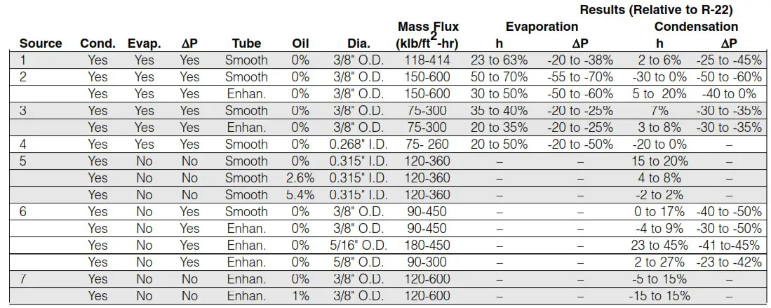
A number of researchers from tubing, system, and refrigerant manufacturers and universities have conducted studies on the heat transfer and pressure drop characteristics of Genetron® AZ-20® R-410A. The table below summarizes results from seven different sources. The results indicate a consistent increase in the evaporation heat transfer coefficient averaging 40% higher than R-22. Condensation values are similar to R-22. The pressure drop is significantly less than R-22 in both evaporation and condensation, averaging close to 40% lower in both cases.
For additional information on these results, please contact Genetron Refrigerants Technical Service.
Heat Transfer Information — Inside Tube
Electrical Properties
Breakdown Voltage and
Dielectric Strength
| Breakdown Voltage volts |
Temp. °F |
Pressure psia |
d (Gap) inches |
| 9580 | 45 | 145 | 0.02 |
| 17000 | 77 | 239 | 0.02 |
| 28100 | 110 | 380 | 0.02 |
| 55400 | 45 | 145 | 0.1 |
| 92500 | 77 | 239 | 0.1 |
| 148300 | 110 | 380 | 0.1 |
| 9580 | 45 | 145 | 0.02 |
| 17000 | 77 | 239 | 0.02 |
| 28100 | 110 | 380 | 0.02 |
| 55400 | 45 | 145 | 0.1 |
| 92500 | 77 | 239 | 0.1 |
| 148300 | 110 | 380 | 0.1 |
| 8600 | 5 | 931 | 0.05 |
| 16700 | 25 | 1649 | 0.05 |
| 32600 | 50 | 3058 | 0.05 |
| 50700 | 5 | 931 | 0.25 |
| 91200 | 25 | 1649 | 0.25 |
| 170900 | 50 | 3058 | 0.25 |
| English Dielectric Strength 50.8 kV/inch @ 1 atm, 77°F Breakdown Voltage*, volts = -1876 + 3952 P (psia) d (inches) SI Dielectric Strength 20.0 kV/[email protected] kPa, 25°C Breakdown Voltage*, volts = -1876 + 226 P (kPa) d (cm) |
|||
*equations derived from measurements per ASTM D2477
Materials Compatibility
The stability of Genetron ® AZ-20 ® R-410A with metals is excellent.
Laboratory testing has shown that Genetron AZ-20 is compatible with steel, copper, aluminum, and brass. The stability of refriger ant/oil mixtures is determined using the ASHRAE 97 sealed tube method. AZ-20 was studied with several lubricants. The tests were conducted in the presence of steel, copper, and aluminum. The time of the exposure was two weeks, with the temperature of the exposure being 400°F (204°C). The stability was judged by both visual observation and measuring the fluoride concentration in the tubes.
A typical example of the results of such tests with three different lubricants is shown. The visual appearance of the metals and the lubricant is unchanged. In addition, the amount of fluoride produced in the tube is just barely above the background con centration. This indicates that the lubricant, metals, and refrig errant are compatible under the extreme conditions of the tests.
Stability with Polyol EsterLubricants and Metals
| Lubricant | Lubricant Appearance | Copper | Aluminum | Steel | Fluoride AZ-20 (p.g) , Purity | |
| Mobil Eal 22 | No Change | No Chang | No Change | No Change | No Change | |
| Mobil Eal 32 | No Change | No Chang | No Change | No Change 6 | No Change | |
| Castro! SW 32 |
No Change | No Chang | No Change | No Change 10 |
No Change | |
Note: Test performed at 400°F (204°C) for 14 days.
Chlorinated Materials and Refrigerants
Honeywell does not recommend the use of chlorinated solvents to clean refrigeration systems or components.
Desiccants
Desiccant driers compatible with Genetron AZ-20 are commercially available from several drier manufacturers.
Individual drier manufacturers should be contacted for specific recommendations.
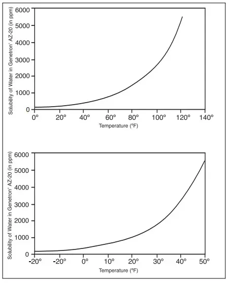
Solubility of Water in Genetron® AZ-20®
Compatibility with Plastics and Elastomers
The table below is a summary of materials compatibility data resulting from tests performed by Honeywell and other worldwide organizations.
Since there are many different grades and formulations of these materials, we recommend that compatibility testing be per formed on the specific grade of materials under consideration when designing new systems.
This data should be used only as a guide to the compatibility of materials with Genetron® AZ-20® R-410A.
The rankings in the table below should be used with caution since they are judgments based on limited samplings. Customers should consult with the manufacturer or conduct further independ ent testing.
Summary of Materials Compatibility:
Plastics and Elastomers
| Material | AZ-20 |
| Ethylene-Propylene Diene Terpolymer | S |
| Ethylene-Propylene Copolymer | S |
| Chlorosulfonated Polyethylene | S |
| Chlorinated Polyethylene | D |
| Neoprene (Chloroprene) | S |
| Epichlorohydrin | D |
| Fluorinated Rubbers | U |
| Silicone Polyurethane | D |
| Nitriles | D |
| H-NBR | D |
| Butyl Rubber | D |
| Polysulfide | S |
| Nylon | S |
| Polytetrafluoroethylene | S |
| PEEK | S |
| ABS | U |
| Polypropylene | D |
| Polyphenyl Sulfide | U |
| Polyethylene Terephthalate | D |
| Polysulfone | D |
| Polyimide | S |
| Polyetherimide | S |
| Polyphthalamide | D |
| Polyamide-imide | S |
| Acetal | D |
| Phenolic | S |
S: Suitable
D: Suitability dependent on the formulation
U: Unsuitable
Lubricants
As with other HFCs, miscible lubricants such as polyol ester lubricants are recommended for use with Genetron AZ-20. Many polyol ester lubricants are commercially available. Castrol SW 32 and Mobil EAL 32 are two polyol ester lubricants that were test ed by Honeywell. Within a temperature range of -40°F to 140°F (-40°C to 60°C) and a concentration up to 50% lubricant, these two lubricants exhibited complete miscibility with Genetron AZ-20.
Honeywell does not recommend specific lubricants. The compres sor and lubricant manufacturers should be consulted for a specific recommendation.
Safety
Honeywell recommends reading the MSDS before using Genetron AZ-20. Any Genetron MSDS can be obtained through our MSDS request line at 1-973-455-3680 or downloaded from www.genetron.com.
Toxicity
Genetron AZ-20 can be safely used in all of its intended applica tions when handled in accordance to the Material Safety Data Sheet (MSDS). This is based on data developed by the Program for Alternative Fluorocarbon Toxicity Testing (PAFTs, III and V), an international consortium of which Honeywell is a charter member.
The conclusion was reached after a review of all toxicity results, which confirmed the intrinsically low toxicity of the components.
Honeywell recommends reading the MSDS before using Genetron AZ-20.
Inhalation
Honeywell has established an occupational exposure limit (8-hour time-weighted average) of 1000 ppm for Genetron AZ-20.
Inhalation of the product’s vapor may cause irritation. Vapor inhalation at high concentrations may result in asphyxiation or the heart may become sensitized, causing the cardiac arrhythmia.
Because of possible disturbances of cardiac rhythm, cate choline drugs, such as epinephrine, should be used with spe cial caution only in situations of emergency life support. Treatment of overexposure to Genetron AZ-20 should be directed at the con control of symptoms.
When concentrations of Genetron AZ-20 reach levels that reduce oxygen to 14-16% by displacement, symptoms of asphyxiation will occur. An individual exposed to high concentra tions of Genetron AZ-20 must be given medical attention imme diately. Adequate ventilation must be provided at all times.
Skin and Eye Contact
Genetron® AZ-20® R-410A vapors can irritate the skin and eyes. In liquid form, it can freeze skin or eyes on contact. If contact with the skin should occur, flush the exposed area with lukewarm water until all of the chemicals is removed. If there is evidence of frost bite, bathe in lukewarm water. Should eye contact occur, immedi Italy flush with large amounts of lukewarm water for at least 15 minutes, lifting eyelids occasionally to facilitate irrigation? Seek medical attention as soon as possible.
Leaks
If a large release of Genetron AZ-20 vapor occurs, the area should be evacuated immediately. Protected personnel should de-energize or remove any ignition sources and address leaks, if without risk. Vapors may concentrate near the floor, displacing available oxygen. Once the area is evacuated, it must be venti late using blowers or fans to circulate the air at floor-level. Unprotected personnel should not return to the area until the air has been tested and determined safe. Leak checking should never be done with a mixture of Genetron AZ-20 and air, oxygen or other oxidizers. Leak checking can be performed safely using a mixture of Genetron AZ-20 and nitrogen.
Flammability
According to ASHRAE Standard 34, Genetron AZ-20 is classified in safety group A1, i.e., it is non-flammable at 1 Atm. pressure (101.3 kPa) and 64°F (18°C). As defined by the U.S. Department of Transportation (DOT) regulations, flash-point determinations do not apply to Genetron AZ-20. It has no flame limits, and DOT considers it non-flammable (Green Label).
In addition, Underwriters’ Laboratory has recognized Genetron AZ-20 as practically non-flammable. Since Genetron AZ-20 does not have a flash point and is non-flammable, Honeywell believes that standard industrial-type electrical installations may be used. It is essential to review and comply with all local building codes and other applicable regulations and laws when using Genetron AZ-20 or any other similar product.
Combustibility
Although Genetron AZ-20 is non-flammable at ambient tempera tures and atmospheric pressures, it can become combustible under pressure when mixed with air.
Because of this combustibility potential under pressure, Genetron AZ-20 and air, oxygen or other oxidizers should never be mixed in tanks or supply lines, or allowed to accumulate in storage tanks. Leak-checking should never be done with a mixture of Genetron AZ-20 and air, oxygen or other oxidizers.
Leak-checking can be performed safely with a mixture of Genetron AZ-20 and nitrogen.
Thermal Stability
It is important to avoid exposing Genetron AZ-20 to very high temperatures. When exposed to high temperatures, such as those found in flames, Genetron AZ-20 vapors will decompose.
This will produce toxic and irritating compounds. Pungent odors released will irritate the nose and throat and generally force evacuation of the area.
Genetron AZ-20 is stable under normal operating conditions.
Contact with certain red-hot metals may result in exothermic or explosive reactions and yield toxic and/or corrosive decomposi tion products. Specific materials to avoid include freshly abrad ed aluminum surfaces and active metals such as sodium, potas sodium, calcium, powdered aluminum, magnesium, and zinc.
Storage and Handling
Bulk and Cylinder
Genetron AZ-20 has a higher vapor pressure compared to most of the current refrigerants, particularly Genetron 22 (HCFC-22). For this reason, Genetron AZ-20 must be handled with careful attention to the design pressure rating of the handling equipment. All storage shipping containers — cylinders, storage tanks, tank trailers or tank cars — must be specifically designed to handle Genetron AZ-20.
Another important handling practice that must be followed for Genetron AZ-20 is to ensure that all transfers be executed by using liquid charging instead of vapor charging. This practice will help minimize compositional changes.
Genetron AZ-20 cylinders must be clearly marked and kept in a cool, dry and properly ventilated storage area away from heat, flames, corrosive chemicals, fumes, explosives and be otherwise protected from damage. Disposable Jugs™ should be discarded in an environmentally safe manner in accordance with all laws and regulations.
Empty cylinders should be returned to Honeywell or your Genetron Wholesaler. Under no circumstance should anything be put into the empty cylinder? Prior to disposal, cylinder con tents should be recovered to an internal pressure of 0 psig or less. Once empty, properly close the cylinder valve and replace the valve cap.
Keep cylinders of Genetron® AZ-20® R-410A out of direct sun light, especially in warm weather. Genetron AZ-20 expands signif icantly when heated, reducing the amount of vapor space left in the cylinder. Once the cylinder becomes liquid-full, any further rise in temperature can cause it to burst, potentially resulting in serious personal injury. NEVER ALLOW A CYLINDER TO GET WARMER THAN 125°F (52°C).
Always store cylinders above dirt or damp floors to prevent rust ing, using a platform or parallel rails. SECURE CYLINDERS IN PLACE BY MEANS OF A RACK, CHAIN, OR ROPE TO PREVENT THEM FROM TIPPING, FALLING, ROLLING OR CCIDENTALLY STRIKING EACH OTHER OR ANY OTHER OBJECT. If the cylinder valve is broken off, rapid escape of the high-pressure contents will propel the cylinder, which could potentially result in serious injury. Keep cylinder caps in place until the cylinder is in use.
The storage area should be away from corrosive chemicals or fumes to avoid damaging effects on the cylinder and threaded areas of the valve. Follow similar precautions for bulk storage and transport systems, ensuring that proper design and operation satisfies the required pressure rating and also avoids external corrosive conditions, overheating or overfilling.
If a cylinder leak is detected, contact Honeywell for guidance.
Maintenance
A thorough pre-job review must be done to determine respirato ry protection requirements, as well as any other safety equipment needed. Maintenance in areas where Genetron AZ-20 has accu emulated should be performed only after confirming that work area concentrations are below the permissible exposure level (PEL). This may be determined using a vapor-in-air analyzer capable of measuring the amount of airborne Genetron AZ-20.
These vapors are heavier than air and can accumulate at floor level. When vapor concentrations are above the PEL, the area should be ventilated to reduce the vapor concentration to below the PEL before entry. Ventilate the area using fans and other air movers as necessary. If the entry must be made to areas where vapor concentrations are above the PEL, appropriate respiratory protection should be used.
Federal occupational health and safety agencies often have legal requirements and guidelines for proper selection and use of respiratory protection. It is often the responsibility of the employer to ensure the safety of the employees performing the maintenance. Be sure to comply with applicable laws and guidelines for proper selection and use of respiratory protection. If the airborne concentration of refrigerant is unknown or at a par particular threshold, the law may require the use of supplied air res pirates. Particular work team and work zone entry procedures may also apply. Vessels, containers, transfer lines, pumps, and other equipment should not be exposed to high-temperature sources (such as welding, brazing, and open flames) until they have been thoroughly cleaned and found free of vapors.
Exposure to these circumstances can cause fire, explosion, and decomposition of refrigerant. This may result in the formation of toxic or corrosive compounds. Potential sources for further vapor releases should also be eliminated if possible.
When possible, maintenance or cleaning of equipment should be performed without entering the vessel. A tank or storage ves sel may be a confined space. These spaces may have a config uration that can hinder activities and/or expose personnel to the risk of physical injury from entrapment, engulfment, or hazardous atmospheres. Depending on conditions and applicable regula tions, a permit may be required to enter such vessels. If a tank must be entered, personnel should be required to use a formal tank entry procedure based on recognized safety principles and comply with all applicable regulations. The procedure would provide guidance for critical items such as but not limited to respiratory protection, safety equipment, work practice, and communication. Among the possible requirements of these
procedures is the use of a fully qualified work team and placement of a confined space entry permit at the job site.
Leak Detection
Use leak detectors for pinpointing leaks or for monitoring an entire room on a continual basis. Leaks detectors are important for refrigerant conservation, equipment protection, and performance, reduction of emissions, and protection of those coming in contact
with the system.
Leak testing should not be performed using mixtures of air and Genetron® AZ-20®. There are two types of leak detectors — leak pinpointers and area monitors. Before purchasing either type, several equipment factors should be considered, including detec tion limits, sensitivity, and selectivity. Regarding selectivity, there are three categories: non-selective, halogen-selective, and com pound selective. In general, the complexity and cost of a leak detec tor increase as the specificity increases. Fluorescent dye approved by the equipment manufacturer can be added to sys tem to help pinpoint leaks.
New installations should be checked for leaks prior to complete charging. Whenever a leak inspection is performed, check all factory and field joints throughout the system. For a system that has been in operation for some time, check for oil at joints and connections, as this may serve as an indication of a refrigerant leak at that location. This approach would not commonly be con considered when leak checking a new system installation since it is much less likely that oil will have found its way to the leak.
If a system has lost all or most of its refrigerant charge, the sys tem must be pressurized to about 150 psig in order to perform a leak check. Pressure can be restored for leak checking by adding Genetron AZ-20 R-410A using normal charging procedures or by using dry nitrogen. DO NOT USE AIR TO LEAK CHECK THE SYSTEM. (At pressures above atmospheric, mixtures of air and Genetron AZ-20 R-410A, like R-22, will become combustible.) For a system containing either all refrigerant or a mixture of refrigerant and nitrogen, an electronic leak detector can be used. The leak detector must be capable of detecting a hydrofluorocarbon (HFC) refrigerant. Older leak detectors designed for R-22 will not be sensitive enough to effectively detect HFC refrigerants. Halide torches can not effectively detect
HFC refrigerant leaks. NITROGEN IS A HIGH-PRESSURE GAS, REMEMBER TO USE A PRESSURE REGULA TOR COMING OFF THE NITROGEN TANK TO AVOID ANY RISK OF SEVERE PERSONAL INJURY.
A simple way to test for leaks is to use a solution of soap and water. Commercial soap solutions for leak detection tend to be more effective. Apply the solution to joints and connections.
The generation of bubbles will indicate a pinhole leak. Several min utes may be required to generate a bubble in the case of a very small leak. When it is suspected that essentially no refrigerant remains in the system, the above method can be used to detect leaking nitrogen gas. However, the most convenient and effective means to detect a leak when Genetron® AZ-20® is in the system is to use an electronic leak detector designed for HFC refrigerants.
When a leak is found, the refrigerant must be recovered and the leak repaired prior to final charging and operation. If the refriger ant charge is 50 pounds or more, the system is subject to leak repair requirements under the Refrigerant Recycling Regulations of Section 608 of the Clean Air Act Amendments of 1990. In this case, the equipment owner must keep a record of the date and type of service performed and the amount of refrigerant added.
Retrofitting Existing Systems
Genetron AZ-20 is the long-term non-ozone-depleting replace ment for HCFC-22 in new equipment due to its many favorable performance characteristics. However, the performance proper ties which make it the replacement for HCFC-22 in new equipment — higher capacity and higher pressure — make it difficult to be used in existing systems designed for HCFC-22. In most cases, mandatory changes would include compressors and thermostat ic expansion valves. Condensers and other high-pressure-side components may also require replacement. Depending on the applicable design standard for pressure-containing components and the particular design, even low-pressure-side components may require changing. Provided local building codes permit, and equipment manufacturers approve, it may be possible to retain the indoor coil and inter-connecting lines.
When converting an existing R-22 residential air-conditioning system to Genetron AZ-20 R-410A, the condensing unit will have to be replaced with one designed for R-410A. If the expansion device is a short tube orifice, it can typically be modified using a kit available from the manufacturer. An R-22 thermostatic expan sion valve (TXV) must be replaced with an R-410A TXV. It is also important to install a compatible liquid-line filter drier. If water or acid needs to be removed, consult the equipment manufacturer’s application information or service manual. Confirm with the equipment manufacturer that the existing indoor coil is suitable–some existing indoor coils (capillary tube or pre-1980’s design) are not acceptable for use with Genetron AZ-20. Indoor sections must be UL approved for appropriate service pressure ratings. The service pressure rating for Genetron AZ-20 is 235 psig. Indoor coils listed for R-22 heat pump
applications would meet or exceed this rating. In most cases, existing line sets can be used.
Be certain to follow the equipment manufacturer’s procedures for pump-down and recovery of the original R-22 charge and for instal location of the new condensing unit, expansion device, and liquid-line filter drier. For a residential air-conditioning retrofit where indoor coil and lines stay, it is important to drain residual mineral oil or alkylben zene oil from the system. Systems charged with R-410A can tolerate a small mineral oil residual. Pay particular attention to low spots in the suction line and evaporator where oil may have accumulated. Never leave a system open to the atmosphere for more than 15 minutes.
A miscible lubricant such as polyol ester (POE) lubricant must be used with Genetron AZ-20 R-410A refrigerant. Refer to the equipment manufacturer for a list of approved lubricants since lubricants are not always interchangeable. POE lubricant readily absorbs moisture; therefore, care should be taken to minimize exposure of the lubricant to the atmosphere. Use a pump to trans fer lubricant; do not pour. In an air-conditioning system, a filter drier can be used to effectively remove moisture from POE lubricant; A VACUUM PUMP WILL NOT WORK.
After the new condensing unit, expansion device, and liquid-line filter drier have been installed, evacuate the system to 500 microns to ensure that air and liquid water are effectively removed from the system. Once a system is under a vacuum, does not open to the atmosphere. Break vacuum using Genetron AZ-20 or if a triple evacuation method is being used, break vacuum using 2-3 psig dry nitrogen. Once certain that there are no leaks, weigh in the refrigerant charge using a dial-a-charge designed for Genetron AZ-20 or a digital scale.
Charge Optimization
Standard superheat and subcooling procedures can be used to optimize the refrigerant charge. Fixed restrictor-type metering devices require charge optimization using the superheat method. A system charged with Genetron AZ-20 and equipped with an R-410A TXV (thermostatic expansion valve) requires use of the subcooling method for refrigerant charge optimization. Do not use an R-22 TXV with Genetron AZ-20.
For a typical 3/8-inch outer diameter liquid line, long line applications will require approximately 0.50 oz. of refrigerant per foot of additional length. Charging units with long refrigerant lines must be done carefully since pressure and temperature changes occur more slowly. Add or remove refrigerant in small increments (about 5% by weight of the original system charge) and allow the system to stabilize between each.
LIQUID CHARGE USING A COMMERCIAL METERING DEVICE IN THE MANIFOLD HOSE. CHARGE INTO THE SUCTION LINE.
Consult Honeywell’s Genetron® AZ-20® (R-410A) Air-Conditioning System Charging and Recovery Guidelines (publication
G-525-083) for more detailed information on charge optimization.
Filter Driers
Liquid-line filter driers must have rated working pressures of no less than 600psig. Honeywell recommends the use of a liquid-line filter
drier. Be certain not to install a suction-line drier in the liquid line.
The filter drier should be approved for R-410A refrigerant. Remove a filter drier from the system by using a tubing cutter. Do not unsweat a filter drier since heat will release moisture and contami nants from the drier into the system.
Environmental Considerations
Genetron AZ-20 is a halogenated hydrocarbon. Treatment or disposal of wastes generated by use of this product may require special consideration, depending on the nature of the wastes and the means of discharge, treatment or disposal. For more information, refer to the Material Safety Data Sheet (MSDS).
If discarded unused, Genetron AZ-20 is not considered a “haz arduous waste” by the Resource Conservation and Recovery Act (RCRA). Because Genetron AZ-20 is considered to have mini mum biodegradability, care should be taken to avoid releases to the environment.
The disposal of Genetron AZ-20 may be subject to federal, state and local regulations. Users should conduct disposal operations in compliance with applicable federal, state, and local laws and regulations. Appropriate regulatory agencies also should be consulted before discharging or disposing of waste materials.
Refrigerant Recovery,
In the United States, amendments to the 1990 Clean Air Act require mandatory recycling and reclamation of refrigerants during maintenance, servicing, or repair of air-conditioning or refrigeration equipment. This includes HFC (hydrofluorocarbon) refrigerants such as Genetron AZ-20. The venting of refrigerants to the atmos here is prohibited. The recovery or recycling device must be EPA-approved. Recycled refrigerant may only be returned to the equip ment from which it was removed or used in other equipment owned
by the same person.
IT IS VERY IMPORTANT TO MAKE CERTAIN THAT THE RECYCLE OR RECOVERY EQUIPMENT USED IS DESIGNED FOR R-410A. The pressure of the Genetron AZ-20 refrigerant is approximately 60% (1.6 times) greater than that of R 22. Pressure gauges require a range up to 800 psig high-side and 250 PSIG low-side with a 550 psig low-side retard. Hoses need an 800 psig service pressure rating. Recovery cylinders require a 400 psig service pressure rating — DO NOT PUT GENETRON® AZ 20® R-410A IN A 300 PSIG RATED CYLINDER. DOT 4BA400 and DOT 4BW400 vessels are acceptable.
The refrigerant that is too contaminated for reuse must be properly disposed of or reclaimed. Reclamation can only be performed at an EPA (Environmental Protection Agency) approved reclamation facility. Most Genetron refrigerant wholesalers will accept recov ered Genetron AZ-20 for reclamation.
Packaging
Genetron AZ-20 is available in a variety of containers. They include 25-lb disposable Jugs™, 100-lb returnable cylinders, and one ton (1450-lb) returnable tanks. Bulk tank trailers and so tanks are available. Consult your Genetron Sales Representative if a larger container is required.
Available Literature/Technical Assistance
Honeywell has a wide range of literature available for all of its environmentally safer Genetron products, covering such topics as reclamation, retrofitting guidelines, product specifications, and physical properties. In addition, Honeywell technical specialists are available to assist you in all aspects of using Genetron AZ-20 — handling and storage and applications assistance. For further information, please write us at:
Honeywell Genetron Refrigerants
P.O. Box 1053
Morristown, NJ 07962-1053
Or call us at 1-800-631-8138
Thermodynamic Table — English Units
| Temp °F |
Pressure Asia |
Liquid Density 3 lb/ft |
Vapor volume 3 ft /lb |
Enthalpy Cliq Btu/lb |
Enthalpy Dh Btu/lb | Enthalpy Hvap Btu/lb |
Entropy Sliq Btu/lb °F |
Entropy Swap Btu/lb °F |
| -60 | 14.9 | 84.1928 | 3.7914 | -6.6 | 117.29 | 110.69 | -0.0161 | 0.2775 |
| -58 | 15.8 | 83.974 | 3.5965 | -5.95 | 116.89 | 110.94 | -0.0144 | 0.2766 |
| -56 | 16.7 | 83.7544 | 3.4136 | -5.29 | 116.47 | 111.18 | -0.0128 | 0.2758 |
| -54 | 17.6 | 83.5341 | 3.2418 | -4.63 | 116.06 | 111.43 | -0.0112 | 0.275 |
| -52 | 18.6 | 83.313 | 3.0803 | -3.97 | 115.64 | 111.67 | -0.0096 | 0.2742 |
| -50 | 19.7 | 83.0912 | 2.9285 | -3.31 | 115.23 | 111.92 | -0.008 | 0.2734 |
| -48 | 20.7 | 82.8686 | 2.7856 | -2.65 | 114.81 | 112.16 | -0.0064 | 0.2726 |
| -46 | 21.8 | 82.6452 | 2.6511 | -1.99 | 114.38 | 112.39 | -0.0048 | 0.2718 |
| -44 | 23 | 82.421 | 2.5243 | -1.33 | 113.96 | 112.63 | -0.0032 | 0.271 |
| -42 | 24.2 | 82.1959 | 2.4048 | -0.66 | 113.53 | 112.87 | -0.0016 | 0.2703 |
| -40 | 25.5 | 81.97 | 2.2921 | 0 | 113.1 | 113.1 | 0 | 0.2696 |
| -38 | 26.8 | 81.7432 | 2.1857 | 0.67 | 112.66 | 113.33 | 0.0016 | 0.2688 |
| -36 | 28.1 | 81.5155 | 2.0853 | 1.33 | 112.23 | 113.56 | 0.0031 | 0.2681 |
| -34 | 29.5 | 81.2869 | 1.9903 | 2 | 111.79 | 113.79 | 0.0047 | 0.2674 |
| -32 | 31 | 81.0573 | 1.9006 | 2.67 | 111.35 | 114.02 | 0.0063 | 0.2667 |
| -30 | 32.5 | 80.8268 | 1.8157 | 3.34 | 110.91 | 114.25 | 0.0078 | 0.266 |
| -28 | 34.1 | 80.5952 | 1.7353 | 4.01 | 110.46 | 114.47 | 0.0094 | 0.2653 |
| -26 | 35.7 | 80.3627 | 1.6592 | 4.68 | 110.01 | 114.69 | 0.0109 | 0.2646 |
| -24 | 37.4 | 80.1291 | 1.587 | 5.36 | 109.55 | 114.91 | 0.0125 | 0.264 |
| -22 | 39.2 | 79.8945 | 1.5187 | 6.03 | 109.1 | 115.13 | 0.014 | 0.2633 |
| -20 | 41 | 79.6588 | 1.4538 | 6.71 | 108.63 | 115.34 | 0.0155 | 0.2627 |
| -18 | 42.9 | 79.4219 | 1.3923 | 7.39 | 108.17 | 115.56 | 0.0171 | 0.262 |
| -16 | 44.9 | 79.1839 | 1.3339 | 8.07 | 107.7 | 115.77 | 0.0186 | 0.2614 |
| -14 | 46.9 | 78.9447 | 1.2784 | 8.75 | 107.23 | 115.98 | 0.0201 | 0.2608 |
| -12 | 49 | 78.7044 | 1.2256 | 9.43 | 106.75 | 116.18 | 0.0216 | 0.2601 |
| -10 | 51.2 | 78.4628 | 1.1755 | 10.11 | 106.28 | 116.39 | 0.0231 | 0.2595 |
| -8 | 53.4 | 78.2199 | 1.1278 | 10.8 | 105.79 | 116.59 | 0.0246 | 0.2589 |
| -6 | 55.7 | 77.9757 | 1.0823 | 11.48 | 105.31 | 116.79 | 0.0261 | 0.2583 |
| -4 | 58.1 | 77.7302 | 1.0391 | 12.17 | 104.82 | 116.99 | 0.0276 | 0.2577 |
| -2 | 60.6 | 77.4834 | 0.9979 | 12.86 | 104.33 | 117.19 | 0.0291 | 0.2571 |
| 0 | 63.1 | 77.2351 | 0.9587 | 13.55 | 103.83 | 117.38 | 0.0306 | 0.2566 |
| 2 | 65.8 | 76.9854 | 0.9213 | 14.25 | 103.32 | 117.57 | 0.0321 | 0.256 |
| 4 | 68.5 | 76.7342 | 0.8856 | 14.94 | 102.82 | 117.76 | 0.0336 | 0.2554 |
| 6 | 71.3 | 76.4816 | 0.8516 | 15.64 | 102.31 | 117.95 | 0.0351 | 0.2548 |
| 8 | 74.2 | 76.2273 | 0.8191 | 16.34 | 101.79 | 118.13 | 0.0366 | 0.2543 |
| 10 | 77.1 | 75.9715 | 0.788 | 17.04 | 101.27 | 118.31 | 0.0381 | 0.2537 |
| 12 | 80.2 | 75.714 | 0.7584 | 17.74 | 100.75 | 118.49 | 0.0395 | 0.2532 |
| 14 | 83.3 | 75.4549 | 0.73 | 18.45 | 100.21 | 118.66 | 0.041 | 0.2526 |
| 16 | 86.6 | 75.194 | 0.7029 | 19.15 | 99.68 | 118.83 | 0.0425 | 0.2521 |
| 18 | 89.9 | 74.9314 | 0.677 | 19.86 | 99.14 | 119 | 0.044 | 0.2516 |
| 20 | 93.4 | 74.6669 | 0.6522 | 20.57 | 98.6 | 119.17 | 0.0454 | 0.251 |
| 22 | 96.9 | 74.4006 | 0.6285 | 21.29 | 98.04 | 119.33 | 0.0469 | 0.2505 |
| 24 | 100.5 | 74.1324 | 0.6057 | 22 | 97.49 | 119.49 | 0.0484 | 0.25 |
| 26 | 104.3 | 73.8621 | 0.584 | 22.72 | 96.93 | 119.65 | 0.0498 | 0.2494 |
| 28 | 108.1 | 73.5899 | 0.5631 | 23.44 | 96.36 | 119.8 | 0.0513 | 0.2489 |
| 30 | 112.1 | 73.3156 | 0.5431 | 24.16 | 95.79 | 119.95 | 0.0527 | 0.2484 |
| 32 | 116.1 | 73.0391 | 0.5239 | 24.89 | 95.21 | 120.1 | 0.0542 | 0.2479 |
| 34 | 120.3 | 72.7604 | 0.5055 | 25.62 | 94.62 | 120.24 | 0.0557 | 0.2474 |
| 36 | 124.6 | 72.4794 | 0.4878 | 26.35 | 94.03 | 120.38 | 0.0571 | 0.2469 |
| 38 | 129 | 72.1961 | 0.4708 | 27.08 | 93.43 | 120.51 | 0.0586 | 0.2463 |
| 40 | 133.5 | 71.9104 | 0.4546 | 27.82 | 92.83 | 120.65 | 0.06 | 0.2458 |
| 42 | 138.1 | 71.6223 | 0.4389 | 28.56 | 92.21 | 120.77 | 0.0615 | 0.2453 |
| 44 | 142.9 | 71.3315 | 0.4239 | 29.3 | 91.6 | 120.9 | 0.0629 | 0.2448 |
| 46 | 147.7 | 71.0382 | 0.4094 | 30.04 | 90.98 | 121.02 | 0.0644 | 0.2443 |
| 48 | 152.7 | 70.7422 | 0.3955 | 30.79 | 90.34 | 121.13 | 0.0658 | 0.2438 |
Thermodynamic Table — English Units — continued
| Temp °F |
Pressure Asia |
Liquid Density³ lb/ft |
Vapor volume³ ft /lb | Enthalpy Cliq Btu/lb |
Enthalpy Dh Btu/lb |
Enthalpy Hvap Btu/lb |
Entropy Sliq Btu/lb °F |
Entropy Swap Btu/lb °F |
| 50 | 157.9 | 70.4433 | 0.3821 | 31.54 | 89.7 | 121.24 | 0.0673 | 0.2433 |
| 52 | 163.1 | 70.1416 | 0.3693 | 32.3 | 89.04 | 121.34 | 0.0687 | 0.2428 |
| 54 | 168.5 | 69.837 | 0.3569 | 33.05 | 88.4 | 121.45 | 0.0702 | 0.2423 |
| 56 | 174 | 69.5293 | 0.345 | 33.82 | 87.72 | 121.54 | 0.0716 | 0.2418 |
| 58 | 179.6 | 69.2184 | 0.3335 | 34.58 | 87.05 | 121.63 | 0.0731 | 0.2413 |
| 60 | 185.4 | 68.9043 | 0.3224 | 35.35 | 86.37 | 121.72 | 0.0745 | 0.2408 |
| 62 | 191.3 | 68.5869 | 0.3117 | 36.12 | 85.68 | 121.8 | 0.076 | 0.2402 |
| 64 | 197.4 | 68.266 | 0.3014 | 36.9 | 84.97 | 121.87 | 0.0774 | 0.2397 |
| 66 | 203.6 | 67.9415 | 0.2915 | 37.68 | 84.26 | 121.94 | 0.0789 | 0.2392 |
| 68 | 210 | 67.6134 | 0.2819 | 38.46 | 83.54 | 122 | 0.0803 | 0.2387 |
| 70 | 216.5 | 67.2814 | 0.2727 | 39.25 | 82.81 | 122.06 | 0.0818 | 0.2382 |
| 72 | 223.1 | 66.9454 | 0.2638 | 40.04 | 82.07 | 122.11 | 0.0833 | 0.2376 |
| 74 | 229.9 | 66.6054 | 0.2552 | 40.84 | 81.31 | 122.15 | 0.0847 | 0.2371 |
| 76 | 236.9 | 66.2611 | 0.2469 | 41.64 | 80.54 | 122.18 | 0.0862 | 0.2366 |
| 78 | 244 | 65.9125 | 0.2388 | 42.44 | 79.77 | 122.21 | 0.0876 | 0.236 |
| 80 | 251.2 | 65.5593 | 0.2311 | 43.25 | 78.98 | 122.23 | 0.0891 | 0.2355 |
| 82 | 258.7 | 65.2013 | 0.2235 | 44.07 | 78.18 | 122.25 | 0.0906 | 0.2349 |
| 84 | 266.3 | 64.8385 | 0.2163 | 44.89 | 77.36 | 122.25 | 0.092 | 0.2344 |
| 86 | 274 | 64.4705 | 0.2092 | 45.72 | 76.53 | 122.25 | 0.0935 | 0.2338 |
| 88 | 282 | 64.0972 | 0.2024 | 46.55 | 75.69 | 122.24 | 0.095 | 0.2332 |
| 90 | 290.1 | 63.7184 | 0.1959 | 47.38 | 74.84 | 122.22 | 0.0965 | 0.2327 |
| 92 | 298.3 | 63.3338 | 0.1895 | 48.23 | 73.96 | 122.19 | 0.098 | 0.2321 |
| 94 | 306.8 | 62.9431 | 0.1833 | 49.08 | 73.07 | 122.15 | 0.0995 | 0.2315 |
| 96 | 315.4 | 62.5461 | 0.1773 | 49.93 | 72.17 | 122.1 | 0.101 | 0.2309 |
| 98 | 324.2 | 62.1424 | 0.1715 | 50.8 | 71.25 | 122.05 | 0.1025 | 0.2303 |
| 100 | 333.2 | 61.7317 | 0.1659 | 51.67 | 70.3 | 121.97 | 0.104 | 0.2296 |
| 102 | 342.4 | 61.3136 | 0.1604 | 52.54 | 69.35 | 121.89 | 0.1055 | 0.229 |
| 104 | 351.8 | 60.8878 | 0.1551 | 53.43 | 68.37 | 121.8 | 0.107 | 0.2283 |
| 106 | 361.4 | 60.4537 | 0.15 | 54.32 | 67.37 | 121.69 | 0.1085 | 0.2277 |
| 108 | 371.2 | 60.0109 | 0.145 | 55.22 | 66.35 | 121.57 | 0.1101 | 0.227 |
| 110 | 381.1 | 59.5588 | 0.1401 | 56.13 | 65.31 | 121.44 | 0.1116 | 0.2263 |
| 112 | 391.3 | 59.0968 | 0.1354 | 57.05 | 64.24 | 121.29 | 0.1132 | 0.2256 |
| 114 | 401.7 | 58.6242 | 0.1308 | 57.98 | 63.14 | 121.12 | 0.1147 | 0.2248 |
| 116 | 412.3 | 58.1402 | 0.1263 | 58.92 | 62.02 | 120.94 | 0.1163 | 0.2241 |
| 118 | 423.1 | 57.6438 | 0.1219 | 59.88 | 60.86 | 120.74 | 0.1179 | 0.2233 |
| 120 | 434.1 | 57.1341 | 0.1176 | 60.84 | 59.68 | 120.52 | 0.1195 | 0.2225 |
| 122 | 445.3 | 56.6098 | 0.1135 | 61.82 | 58.45 | 120.27 | 0.1212 | 0.2217 |
| 124 | 456.8 | 56.0697 | 0.1094 | 62.82 | 57.19 | 120.01 | 0.1228 | 0.2208 |
| 126 | 468.5 | 55.5121 | 0.1055 | 63.83 | 55.89 | 119.72 | 0.1245 | 0.2199 |
| 128 | 480.4 | 54.9352 | 0.1016 | 64.85 | 54.55 | 119.4 | 0.1261 | 0.219 |
| 130 | 492.6 | 54.3368 | 0.0978 | 65.9 | 53.16 | 119.06 | 0.1278 | 0.218 |
| 132 | 505 | 53.7142 | 0.0941 | 66.97 | 51.71 | 118.68 | 0.1296 | 0.217 |
| 134 | 517.7 | 53.0645 | 0.0904 | 68.07 | 50.2 | 118.27 | 0.1314 | 0.2159 |
| 136 | 530.6 | 52.3837 | 0.0868 | 69.19 | 48.62 | 117.81 | 0.1332 | 0.2148 |
| 138 | 543.8 | 51.6673 | 0.0833 | 70.34 | 46.97 | 117.31 | 0.135 | 0.2136 |
| 140 | 557.2 | 50.9094 | 0.0798 | 71.53 | 45.23 | 116.76 | 0.1369 | 0.2124 |
| 142 | 570.9 | 50.1027 | 0.0763 | 72.76 | 43.39 | 116.15 | 0.1389 | 0.211 |
| 144 | 584.9 | 49.2375 | 0.0729 | 74.05 | 41.41 | 115.46 | 0.1409 | 0.2096 |
| 146 | 599.2 | 48.3009 | 0.0694 | 75.39 | 39.3 | 114.69 | 0.1431 | 0.208 |
| 148 | 613.7 | 47.2751 | 0.0659 | 76.81 | 37.01 | 113.82 | 0.1453 | 0.2062 |
| 150 | 628.6 | 46.1339 | 0.0624 | 78.34 | 34.48 | 112.82 | 0.1477 | 0.2043 |
Thermodynamic Table — SI Units
| Temp °F |
Pressure kPa |
Liquid Density kg/m³ | Vapor volume m/kg³ |
Enthalpy Hliq kJ/kg |
Enthalpy Δh kJ/kg |
Enthalpy Hvap kJ/kg |
Entropy Sliq kJ/kg °C |
Entropy Svap kJ/kg °C |
| -30 | 270 | 1280 | 0.0948 | 156.17 | 253.58 | 409.75 | 0.8318 | 1.8749 |
| -29 | 282 | 1276 | 0.0912 | 157.58 | 252.62 | 410.2 | 0.8376 | 1.8725 |
| -28 | 293 | 1273 | 0.0877 | 159 | 251.65 | 410.65 | 0.8433 | 1.87 |
| -27 | 305 | 1270 | 0.0843 | 160.42 | 250.67 | 411.09 | 0.8491 | 1.8677 |
| -26 | 318 | 1266 | 0.0812 | 161.84 | 249.69 | 411.53 | 0.8548 | 1.8653 |
| -25 | 331 | 1263 | 0.0781 | 163.27 | 248.7 | 411.97 | 0.8605 | 1.8629 |
| -24 | 344 | 1259 | 0.0752 | 164.7 | 247.7 | 412.4 | 0.8662 | 1.8606 |
| -23 | 357 | 1256 | 0.0725 | 166.13 | 246.7 | 412.83 | 0.8719 | 1.8583 |
| -22 | 371 | 1252 | 0.0698 | 167.56 | 245.69 | 413.25 | 0.8776 | 1.856 |
| -21 | 386 | 1249 | 0.0673 | 169 | 244.67 | 413.67 | 0.8833 | 1.8538 |
| -20 | 401 | 1245 | 0.0649 | 170.44 | 243.64 | 414.08 | 0.8889 | 1.8516 |
| -19 | 416 | 1242 | 0.0626 | 171.88 | 242.61 | 414.49 | 0.8945 | 1.8493 |
| -18 | 432 | 1238 | 0.0603 | 173.33 | 241.57 | 414.9 | 0.9002 | 1.8471 |
| -17 | 448 | 1234 | 0.0582 | 174.78 | 240.52 | 415.3 | 0.9058 | 1.845 |
| -16 | 465 | 1231 | 0.0562 | 176.23 | 239.47 | 415.7 | 0.9114 | 1.8428 |
| -15 | 482 | 1227 | 0.0542 | 177.69 | 238.4 | 416.09 | 0.917 | 1.8407 |
| -14 | 499 | 1223 | 0.0523 | 179.15 | 237.32 | 416.47 | 0.9226 | 1.8386 |
| -13 | 517 | 1220 | 0.0505 | 180.61 | 236.25 | 416.86 | 0.9282 | 1.8365 |
| -12 | 536 | 1216 | 0.0488 | 182.08 | 235.15 | 417.23 | 0.9337 | 1.8344 |
| -11 | 555 | 1212 | 0.0472 | 183.55 | 234.05 | 417.6 | 0.9393 | 1.8323 |
| -10 | 575 | 1209 | 0.0456 | 185.02 | 232.95 | 417.97 | 0.9449 | 1.8303 |
| -9 | 595 | 1205 | 0.0441 | 186.5 | 231.83 | 418.33 | 0.9504 | 1.8282 |
| -8 | 615 | 1201 | 0.0426 | 187.99 | 230.69 | 418.68 | 0.9559 | 1.8262 |
| -7 | 637 | 1197 | 0.0412 | 189.47 | 229.56 | 419.03 | 0.9615 | 1.8242 |
| -6 | 658 | 1193 | 0.0398 | 190.96 | 228.41 | 419.37 | 0.967 | 1.8222 |
| -5 | 681 | 1190 | 0.0385 | 192.46 | 227.25 | 419.71 | 0.9725 | 1.8202 |
| -4 | 703 | 1186 | 0.0373 | 193.96 | 226.08 | 420.04 | 0.978 | 1.8182 |
| -3 | 727 | 1182 | 0.0361 | 195.46 | 224.91 | 420.37 | 0.9835 | 1.8162 |
| -2 | 751 | 1178 | 0.0349 | 196.97 | 223.72 | 420.69 | 0.989 | 1.8143 |
| -1 | 775 | 1174 | 0.0338 | 198.48 | 222.52 | 421 | 0.9945 | 1.8123 |
| 0 | 801 | 1170 | 0.0327 | 200 | 221.31 | 421.31 | 1 | 1.8104 |
| 1 | 827 | 1166 | 0.0317 | 201.52 | 220.08 | 421.6 | 1.0055 | 1.8084 |
| 2 | 853 | 1162 | 0.0307 | 203.05 | 218.85 | 421.9 | 1.011 | 1.8065 |
| 3 | 880 | 1158 | 0.0297 | 204.58 | 217.6 | 422.18 | 1.0164 | 1.8046 |
| 4 | 908 | 1154 | 0.0288 | 206.12 | 216.34 | 422.46 | 1.0219 | 1.8027 |
| 5 | 936 | 1150 | 0.0279 | 207.66 | 215.07 | 422.73 | 1.0274 | 1.8007 |
| 6 | 965 | 1145 | 0.027 | 209.21 | 213.78 | 422.99 | 1.0328 | 1.7988 |
| 7 | 995 | 1141 | 0.0262 | 210.77 | 212.48 | 423.25 | 1.0383 | 1.7969 |
| 8 | 1025 | 1137 | 0.0254 | 212.33 | 211.16 | 423.49 | 1.0438 | 1.795 |
| 9 | 1057 | 1133 | 0.0246 | 213.89 | 209.84 | 423.73 | 1.0492 | 1.7931 |
| 10 | 1088 | 1128 | 0.0239 | 215.46 | 208.5 | 423.96 | 1.0547 | 1.7912 |
| 11 | 1121 | 1124 | 0.0231 | 217.04 | 207.14 | 424.18 | 1.0602 | 1.7893 |
| 12 | 1154 | 1120 | 0.0224 | 218.63 | 205.76 | 424.39 | 1.0656 | 1.7874 |
| 13 | 1188 | 1115 | 0.0218 | 220.22 | 204.37 | 424.59 | 1.0711 | 1.7855 |
| 14 | 1223 | 1111 | 0.0211 | 221.81 | 202.98 | 424.79 | 1.0765 | 1.7836 |
| 15 | 1258 | 1106 | 0.0205 | 223.42 | 201.55 | 424.97 | 1.082 | 1.7816 |
| 16 | 1295 | 1102 | 0.0199 | 225.03 | 200.11 | 425.14 | 1.0875 | 1.7797 |
| 17 | 1332 | 1097 | 0.0193 | 226.64 | 198.67 | 425.31 | 1.0929 | 1.7778 |
| 18 | 1370 | 1092 | 0.0187 | 228.27 | 197.19 | 425.46 | 1.0984 | 1.7758 |
| 19 | 1408 | 1088 | 0.0181 | 229.9 | 195.7 | 425.6 | 1.1039 | 1.7739 |
| 20 | 1448 | 1083 | 0.0176 | 231.54 | 194.19 | 425.73 | 1.1094 | 1.7719 |
| 21 | 1488 | 1078 | 0.0171 | 233.19 | 192.66 | 425.85 | 1.1148 | 1.77 |
| 22 | 1529 | 1073 | 0.0166 | 234.85 | 191.1 | 425.95 | 1.1203 | 1.768 |
| 23 | 1571 | 1069 | 0.0161 | 236.51 | 189.53 | 426.04 | 1.1258 | 1.766 |
| 24 | 1614 | 1064 | 0.0156 | 238.18 | 187.94 | 426.12 | 1.1313 | 1.764 |
Thermodynamic Table — SI Units — continued
| Temp °F |
Pressure kPa |
Liquid Density kg/m³ |
Vapor volume m³/kg |
Enthalpy Hliq kJ/kg |
Enthalpy Δh kJ/kg |
Enthalpy Hvap kJ/kg |
Entropy Sliq kJ/kg °C |
Entropy Svap kJ/kg °C |
| 25 | 1657 | 1059 | 0.0152 | 239.86 | 186.33 | 426.19 | 1.1368 | 1.7619 |
| 26 | 1702 | 1054 | 0.0147 | 241.55 | 184.7 | 426.25 | 1.1424 | 1.7599 |
| 27 | 1747 | 1048 | 0.0143 | 243.25 | 183.03 | 426.28 | 1.1479 | 1.7578 |
| 28 | 1794 | 1043 | 0.0139 | 244.96 | 181.35 | 426.31 | 1.1534 | 1.7558 |
| 29 | 1841 | 1038 | 0.0135 | 246.68 | 179.64 | 426.32 | 1.159 | 1.7537 |
| 30 | 1889 | 1033 | 0.0131 | 248.41 | 177.9 | 426.31 | 1.1645 | 1.7515 |
| 31 | 1939 | 1027 | 0.0127 | 250.15 | 176.14 | 426.29 | 1.1701 | 1.7494 |
| 32 | 1989 | 1022 | 0.0123 | 251.9 | 174.35 | 426.25 | 1.1757 | 1.7472 |
| 33 | 2040 | 1016 | 0.012 | 253.66 | 172.54 | 426.2 | 1.1813 | 1.745 |
| 34 | 2092 | 1011 | 0.0116 | 255.43 | 170.69 | 426.12 | 1.1869 | 1.7428 |
| 35 | 2145 | 1005 | 0.0113 | 257.22 | 168.81 | 426.03 | 1.1925 | 1.7405 |
| 36 | 2199 | 999 | 0.0109 | 259.01 | 166.91 | 425.92 | 1.1982 | 1.7382 |
| 37 | 2254 | 993 | 0.0106 | 260.82 | 164.97 | 425.79 | 1.2038 | 1.7359 |
| 38 | 2310 | 988 | 0.0103 | 262.65 | 162.98 | 425.63 | 1.2095 | 1.7335 |
| 39 | 2367 | 981 | 0.01 | 264.48 | 160.98 | 425.46 | 1.2152 | 1.7311 |
| 40 | 2426 | 975 | 0.0097 | 266.33 | 158.93 | 425.26 | 1.221 | 1.7286 |
| 41 | 2485 | 969 | 0.0094 | 268.2 | 156.84 | 425.04 | 1.2267 | 1.7261 |
| 42 | 2545 | 963 | 0.0091 | 270.08 | 154.71 | 424.79 | 1.2325 | 1.7235 |
| 43 | 2607 | 956 | 0.0088 | 271.98 | 152.54 | 424.52 | 1.2383 | 1.7209 |
| 44 | 2670 | 950 | 0.0086 | 273.9 | 150.31 | 424.21 | 1.2442 | 1.7182 |
| 45 | 2734 | 943 | 0.0083 | 275.84 | 148.04 | 423.88 | 1.2501 | 1.7155 |
| 46 | 2799 | 936 | 0.0081 | 277.8 | 145.72 | 423.52 | 1.256 | 1.7127 |
| 47 | 2865 | 929 | 0.0078 | 279.77 | 143.35 | 423.12 | 1.2619 | 1.7098 |
| 48 | 2932 | 922 | 0.0076 | 281.77 | 140.92 | 422.69 | 1.268 | 1.7069 |
| 49 | 3001 | 914 | 0.0073 | 283.8 | 138.42 | 422.22 | 1.274 | 1.7038 |
| 50 | 3071 | 907 | 0.0071 | 285.85 | 135.87 | 421.72 | 1.2801 | 1.7007 |
| 51 | 3142 | 899 | 0.0069 | 287.93 | 133.24 | 421.17 | 1.2863 | 1.6975 |
| 52 | 3214 | 891 | 0.0066 | 290.03 | 130.54 | 420.57 | 1.2926 | 1.6941 |
| 53 | 3288 | 883 | 0.0064 | 292.17 | 127.75 | 419.92 | 1.2989 | 1.6906 |
| 54 | 3363 | 874 | 0.0062 | 294.35 | 124.87 | 419.22 | 1.3053 | 1.6871 |
| 55 | 3439 | 865 | 0.006 | 296.57 | 121.89 | 418.46 | 1.3118 | 1.6833 |
| 56 | 3517 | 856 | 0.0058 | 298.83 | 118.81 | 417.64 | 1.3184 | 1.6794 |
| 57 | 3596 | 847 | 0.0056 | 301.13 | 115.61 | 416.74 | 1.3251 | 1.6753 |
| 58 | 3676 | 837 | 0.0054 | 303.5 | 112.27 | 415.77 | 1.3319 | 1.6711 |
| 59 | 3758 | 826 | 0.0052 | 305.92 | 108.79 | 414.71 | 1.339 | 1.6666 |
| 60 | 3842 | 815 | 0.005 | 308.41 | 105.13 | 413.54 | 1.3461 | 1.6618 |
| 61 | 3927 | 804 | 0.0048 | 310.99 | 101.28 | 412.27 | 1.3535 | 1.6567 |
| 62 | 4013 | 792 | 0.0046 | 313.66 | 97.2 | 410.86 | 1.3612 | 1.6513 |
| 63 | 4101 | 778 | 0.0044 | 316.44 | 92.86 | 409.3 | 1.3691 | 1.6455 |
| 64 | 4191 | 764 | 0.0042 | 319.35 | 88.21 | 407.56 | 1.3775 | 1.6392 |
| 65 | 4282 | 748 | 0.004 | 322.43 | 83.17 | 405.6 | 1.3862 | 1.6322 |
Notes
_____________________________
_____________________________
Worldwide Sales Offices
For more information contact your
Honeywell Refrigerants representative
United States
Honeywell Chemicals
101 Columbia Road
Morristown, NJ 07962-1053
Phone: 800-631-8138
Fax: 973-455-6395
![]()
G 525-013
Printed in the U.S.A.
© 2006 Honeywell International Inc.