Honeywell Smart Switch In-Wall User Manual
SUPPORT
https://mywebtech.honeywellhome.com
MyWebTech
U.S. WARRANTY
https://www.security.honeywellhome.com/hsc/resources/wa/index.html

Warranty
WARNING
RISK OF FIRE
RISK OF ELECTRICAL SHOCK
RISK OF BURNS
CONTROLLING APPLIANCES
CAUTION:
- DO NOT EXCEED RATINGS
- DO NOT USE TO CONTROL ANY DEVICE WHERE UNINTENDED OPERATION COULD CAUSE UNSAFE CONDITIONS (HEAT LAMP, SUN LAMP, ETC.)
- DO NOT USE TO CONTROL RECEPTACLES
- FOR INDOOR USE ONLY
NOT FOR USE WITH MEDICAL OR LIFE-SUPPORT EQUIPMENT
Z-WAVE ENABLED DEVICES SHOULD NEVER BE USED TO SUPPLY POWER TO OR CONTROL THE ON/OFF STATUS OF MEDICAL OR LIFE-SUPPORT EQUIPMENT.
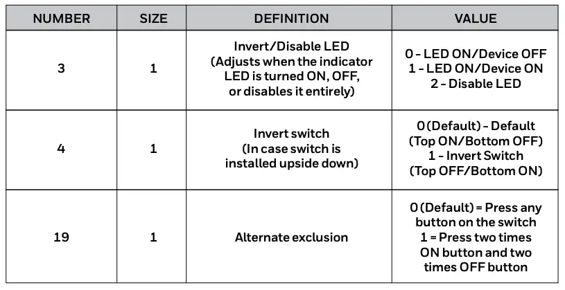
PARAMETERS
This Z-Wave smart switch has advanced features that allow you to customize your experience — these features can only be adjusted by a Z-Wave enabled controller that supports the Z-Wave configuration command class.

SPECIFICATIONS
ZW4005
Power: 120VAC, 60Hz.
Signal (Frequency): 908.4/916MHz
Maximum Loads: 960W, incandescent, 1/2HP motor or 1800W (15A) resistive
Range: Up to 150ft. line of sight between the wireless controller and the closest Z-Wave receiver module.
Operating temperature range: 32-104° F (0-40° C)
For indoor use only. Specifications subject to change without notice due to continuing product improvement
Z-WAVE INTEROPERABILITY
This product can be included and operated in any Z-Wave network with other Z-Wave certified devices from other manufacturers and/or other applications. All non-battery operated nodes within the network will act as repeaters regardless of vendor to increase reliability of the network.
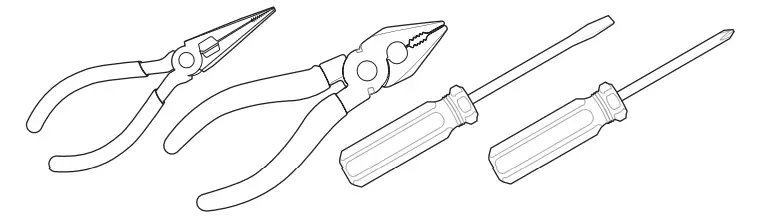
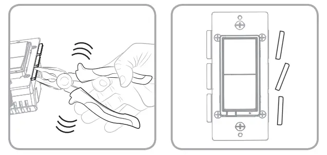
1. TOOLS

IMPORTANT!
The fixture controlled by the Z-Wave In-Wall Smart Switch must not exceed 960W (incandescent); 1800W (15A) resistive or 1/2HP motor. The switch is designed only for use with permanently installed fixtures.
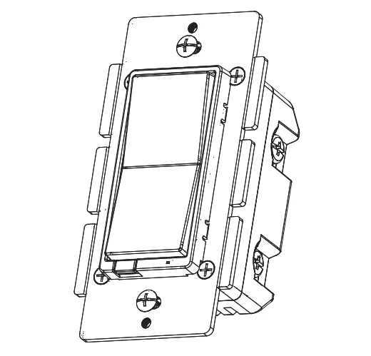
2. FEATURES
- Turn ON/OFF manually or remotely via the Z-Wave controller
- Can be added in multiple groups and scenes
- May be used in single-pole installation or with up to two Honeywell Add-on Switches in 3-way or 4-way wiring configurations
- Compatible with all CFL/LED and incandescent bulbs
- Interchangeable paddle switch — white & light almond paddle in package
- Uses a standard, decorative-size wallplate for single gang installations (wallplate not included)
- Blue LED indicates switch location in a dark room
- Z-Wave certified for simple pairing and integrated home automation
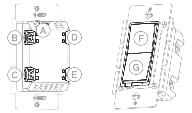
- Screw terminal installation — requires wiring connections for line (hot), load, neutral and ground. Traveler wire required for 3-way or 4-way installation

A. Ground (Green/Bare)
B. Load (Black)
C. Line (Black)
D. Traveler (Red/Other)
E. Neutral (White)
F. Top rocker — Press & release to turn switch ON
G. Bottom rocker — Press & release to turn switch OFF
SINGLE-, DUAL- AND TRIPLE-GANG BOXES
When installing the in-wall smart switch in multiple-gang boxes, it may be necessary to break off one or both sides of the scored tabs on the front yoke. This does not affect the electrical rating of the smart switch (see specifications for details).
3. INSTALLATION
WARNING — SHOCK HAZARD
Turn OFF the power to the branch circuit for the switch and lighting fixture at the service panel. All wiring connections must be made with the POWER OFF to avoid personal injury and/or damage to the switch. This device is intended for installation in accordance with the National Electric Code and local regulations in the United States or the Canadian Electrical Code and local regulations in Canada. If you are unsure or uncomfortable about performing this installation, consult a qualified electrician.
MULTI-SWITCH WIRING
The Honeywell Add-on Switch is required for multi-switch 3-way or 4-way installations. Connecting the traveler terminal of this switch to a standard, non-Honeywell switch will cause damage or result in improper function. If this switch is a part of a 3-way or 4-way multi-switch installation, do not connect the traveler wire or apply power until Honeywell Add-on Switches are correctly installed. For more information on 3-way or 4-way installations, view the manual or quick-start guide that comes with the Honeywell Add-on Switch.
SINGLE-SWITCH WIRING
Before installation, you may wish to change the paddle color to match your wallplate or decor. Please proceed to Section 5.
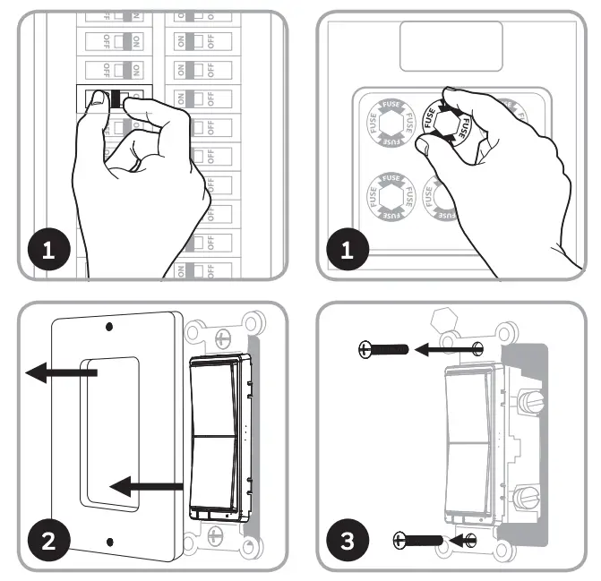
- Shut off power to the circuit at circuit breaker or fuse box.
IMPORTANT! Verify power is OFF to switch box before continuing. - Remove wallplate.
- Remove the switch mounting screws.
- Carefully remove the switch from the switch box. DO NOT disconnect the wires.
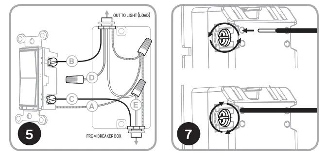
- There are up to five screw terminals on the switch; these are marked:
A. GROUND — Green/Bare
B. LOAD — Black (connected to lighting)
C. LINE (Hot) — Black (connected to power)
D. TRAVELER — Red/Other (only in 3-way installations)
E. NEUTRAL — White Match these screw terminals to the wires connected to the existing switch. - Disconnect the wires from the existing switch. Label wires according to the previous terminal connection.
OBSERVE IMPORTANT WIRING INFORMATION
IMPORTANT! This switch is rated for and intended to only be used with copper wire.
WIRE GAUGE REQUIREMENTS
Use 14 AWG or larger wires suitable for at least 80° C for supplying line (hot), load, neutral, ground and traveler connections.
WIRE STRIP LENGTH - For attachment to screw terminals strip insulation 1in. (25mm). For attachment using the enclosure’s holes: strip insulation 5/8in. (16mm). UL specifies that the tightening torque for the screws is 14 Kgf-cm (12 lbf-in).
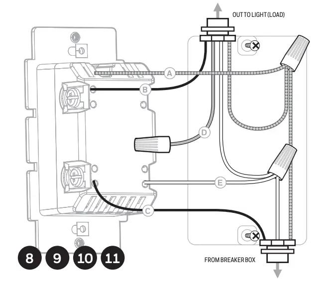
- Connect the green or bare copper ground wire to the GROUND terminal.
- Connect the black wire from the light to the terminal marked LOAD.
- Connect the black wire from the electrical service panel (hot) to the terminal marked LINE.
- Connect the white wire to the NEUTRAL terminal (use a jumper wire if needed).
Note: The traveler terminal is only used for 3-way or 4-way wiring and should remain insulated if the switch is being installed in a single-pole installation (one switch & one load). - Insert switch into the switch box being careful not to pinch or crush wires.
- Secure the switch to the box using the supplied screws.
- Mount the wallplate.
- Reapply power to the circuit at fuse box or circuit breaker and test the system.
BASIC OPERATION
The connected light can be turned ON/OFF in two ways:
- Manually from the front panel of thein-wall switch.
- Remotely with a Z-Wave controller.
MANUAL CONTROL
The front panel rocker switch allows the user to turn ON/OFF the connected fixture.
- To turn the connected fixture ON: Press and release the top of the rocker.
- To turn the connected fixture OFF: Press and release the bottom of the rocker.
DISABLE/ENABLE LED
- Press UP 3 times then quickly press and release DOWN 1 time.
- Repeat to disable/enable LED.
4. CONNECTION
CONNECTING YOUR DEVICE TO A Z-WAVE NETWORK
- Follow the instructions for your Z-Wave certified controller to add a device to the Z-Wave network.
- Once the controller is ready to add your device, press and release the top or bottom of the smart switch (rocker) to add it in the network.
Now you have complete control to turn your fixture ON/OFF according to groups, scenes, schedules and interactive automations programmed by your controller.
If your Z-Wave certified controller features remote access, you can control your fixture from your mobile devices.
REMOVING AND RESETTING THE DEVICE
- Follow the instructions for your Z-Wave certified controller to remove a device from the Z-Wave network.
- Once the controller is ready to remove your device, press and release the top or bottom of the smart switch (rocker) to remove it from the network.
RETURNING SWITCH TO FACTORY DEFAULTS
Quickly press ON (top) button 3 times then immediately press the OFF (bottom) button 3 times. The LED will flash ON/OFF 5 times when completed successfully.
Note: This should only be used in the event your network’s primary controller is missing or otherwise inoperable.
5. CUSTOMIZATION
CHANGING PADDLE COLOR
This step is optional. Before installation, you may want to change the color of the paddle to match your wallplate or decor.
- Lift the air gap tab at the base of the paddle.
- Push side tabs in on one side and then the other to release paddle. Lift the cover up and off.
- Simply put the new paddle onto the switch by inserting the air gap and side tabs and snapping securely into place.
Once this step has been completed, please return to section 3.
FCC / IC – EN
This device complies with Part 15 of the FCC and Industry Canada license-exempt RSS standards. Operation is subject to the following two conditions: (1) this device may not cause harmful interference, and (2) this device must accept any interference received, including interference that may cause undesired operation.
FCC NOTE: The manufacturer is not responsible for any radio or TV interference caused by unauthorized modifications to this equipment. Such modifications could void the user’s authority to operate the equipment.
NOTE: This equipment has been tested and found to comply with the limits for a Class B digital device, pursuant to Part 15 of the FCC Rules. These limits are designed to provide reasonable protection against harmful interference in a residential installation. This equipment generates, uses and can radiate radio frequency energy, and if not installed and used in accordance with the instructions, may cause harmful interference to radio communications. However, there is no guarantee interference will not occur in a particular installation. If this equipment does cause harmful interference to radio or television reception, which can be determined by turning the equipment off and on, the user is encouraged to try to correct the interference by one or more of the following measures:
- Reorient or relocate the receiving antenna.
- Increase the separation between the equipment and receiver.
- Connect the equipment into an outlet on a circuit different to which the receiver is connected.
- Consult the dealer or an experienced radio/TV technician for help.
Important note: To comply with the FCC RF exposure compliance requirements, no change to the antenna or the device is permitted. Any change to the antenna or the device could result in the device exceeding the RF exposure requirements and void user’s authority to operate the device.
FCC — U2ZZW4005A | IC: 6924A-ZW4005A
Model: ZW4005/39455
CAN ICES-3(B)/NMB-3(B)
All brand names shown are trademarks of their respective owners.
The Honeywell Home trademark is used under license from Honeywell International, Inc.
This product is manufactured by Resideo.
MADE IN CHINA
39455 | ZW4005 | 01/08/19 v2
Resideo Technologies, Inc.
2 Corporate Center Dr. Suite 100
P.O. Box 9040
Melville, Ny 11747
www.security.honeywellhome.com | 1-800-645-7492