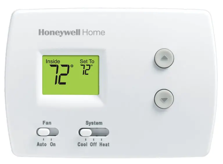
Honeywell TH3110D1008 Non Programmable Digital Thermostat

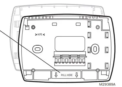
Wallplate installation
Remove the wallplate from the thermostat by pulling from the bottom, then follow directions below for mounting.
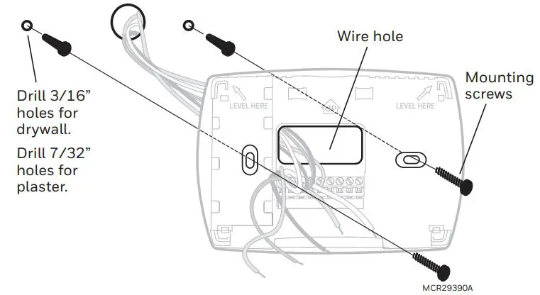
- Pull wires through wire hole.
- Position wallplate on wall, level and mark hole positions with pencil.
- Drill holes at marked positions as shown below, then tap in supplied wall anchors.
- Place wallplate over anchors, insert and tighten mounting screws.
Power options
Wiring terminal designations
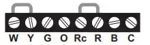
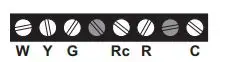
TH3110D
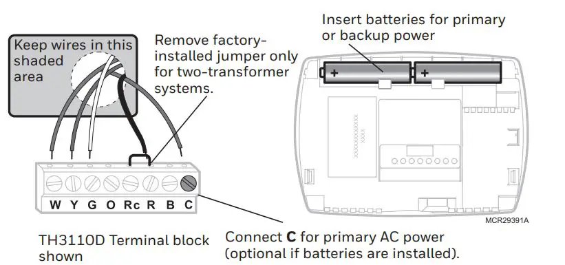
C 24 Vac common. For 2 transformer systems, use common wire from cooling transformer.
B Changeover valve energized in heating
R 24 Vac power from heating transformer
Rc 24 Vac power from cooling transformer
O Changeover valve energized in cooling
G Fan relay
Y Compressor contactor
W Heat relay
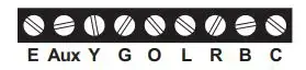
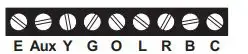
 TH3210D
C 24 Vac common
B Changeover valve energized in heating
R 24 Vac power
L Sends output when set to Em. Heat
O Changeover valve energized in cooling
G Fan relay
Y Compressor contactor
Aux Auxiliary heat relay
E Emergency heat relay
Wiring conventional and heat pump systems
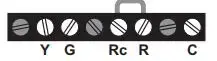
 2H/1C Heat Pump System TH3210D
C 24 Vac common [3]
B Changeover valve energized in heating [5]
R Power [1]
L Sends output when set to Em. Heat [8]
O Changeover valve energized in cooling [5]
G Fan relay
Y Compressor contactor
AUX Auxiliary heat relay [9]
E Emergency heat relay [9]
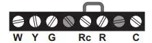
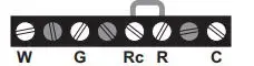
1H/1C Heat Pump System TH3110D [7]
C 24 Vac common [3]
B Changeover valve energized in heating [5
R [R+Rc joined by jumper]
RC Power [1]
O changeover valve energized in cooling [5]
G Fan relay
Y Compressor contactor [6]
W [W+Y joined by jumper]
1H/1C System TH3110D (1 transformer)
C 24 Vac common [3]
R [R+Rc joined by jumper]
RC Power [1]
G Fan relay
Y Compressor contactor
W Heat relay
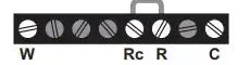
Heat Only System TH3110D
C 24 Vac common [3]
R [R+Rc joined by jumper]
RC Power [1]
W Heat relay
1H/1C System TH3110D (2 transformers)
C 24 Vac common [3, 4]
R Power (heating transformer) [1, 2]
RC Power (cooling transformer) [1, 2]
G Fan relay
Y Compressor contactor
W Heat relay
Heat Only System with Fan TH3110D
C 24 Vac common [3]
R [R+Rc joined by jumper]
RC Power [1]
G Fan relay
W Heat relay
Cool Only System TH3110D
C 24 Vac common [3]
R [R+Rc joined by jumper]
RC Power [1]
G Fan relay
Y Compressor contactor
NOTES
Wire specifications:
Use 18- to 22-gauge thermostat wire. Shielded cable is not required.
- Power supply. Provide disconnect means and overload protection as required.
- Remove jumper for 2-transformer systems.
- Optional 24 Vac common connection.
- Common connection must come from cooling transformer.
- Use either O or B terminals for change-over valve.
- Use a small piece of wire (not supplied) to connect W and Y terminals.
- Set fan operation switch to Heat Pump (see page 5) and configure system type for heat pump (see page 6).
- L terminal sends a continuous output when thermostat is set to Em. Heat. Connect to Honeywell Home zoning pan-els to switch the panel to Emergency Heat.
- Install field jumper between Aux and E if there is no emergency heat relay.
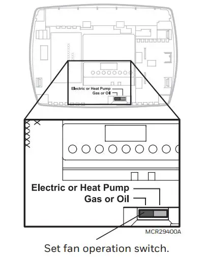
Fan operation settings (TH3110D only)
Gas or Oil: For gas or oil heating systems, leave the fan operation switch in this factory-set position. (This setting is for systems that control the fan in a call for heat.) Electric or Heat Pump: Change the switch to this setting for heat pump or electric heat systems. (This setting is for systems that allow the thermostat to control the fan in a call for heat, if a fan wire is connected to the G terminal.)
Thermostat mounting
1. Align the 4 tabs on the wallplate with corresponding slots on the back of the thermostat.
2. Push gently until the thermostat snaps in place.
3. Push excess wire back into the wall opening.
4. Plug wall opening with non-flammable insulation.
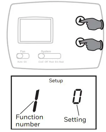
Installer Setup
Follow the procedure below to configure the thermostat to match the installed heating/cooling system, and customize feature operation as desired.
To begin, press and hold the UP and DOWN buttons until the display changes.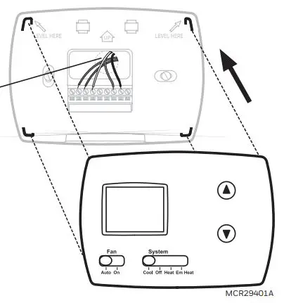
• Press DOWN to change settings.
• Press UP to advance to next function.
• Press and hold DOWN UP to exit and save settings.
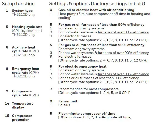
Setup function
Compressor Protection (Setup Function 15): Forces the compressor to wait a few minutes before restarting, to prevent damage. During the wait time, the message Cool On or Heat On (heat pumps only) will flash on the display.
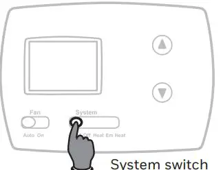
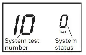
Installer system test
- Set SYSTEM switch to Heat.
- Press DOWN to turn on and check systems (see table, below).
- Press DOWN until systems turn off.
- Set SYSTEM switch to Em Heat and repeat steps 2-3 above (TH3210D only).
- Set SYSTEM switch to Cool and repeat steps 2-3 above.
- Press and hold DOWN UP to terminate test at any time.
System Test
Troubleshooting
If you have difficulty with your thermostat, please try the following suggestions. Most problems can be corrected quickly and easily.
Display is blank
- Check circuit breaker and reset if necessary.
- Make sure power switch at heating & cooling system is on.
- Make sure furnace door is closed securely.
- Make sure fresh AA alkaline batteries are correctly installed (see page 2).
Heating or cooling system does not respond
• Set system switch to Heat. Make sure the temperature is set higher than the Inside temperature.
• Set system switch to Cool. Make sure the temperature is set lower than the Inside temperature.
• Wait 5 minutes for the system to respond.
Temperature settings do not change
Make sure heating and cooling temperatures are set to acceptable ranges:
• Heat: 40° to 90°F (4.5° to 32°C).
• Cool: 50° to 99°F (10° to 37°C).
“Cool On” or “Heat On” is flashing
Compressor protection feature is engaged. Wait 5 minutes for the system to restart safely, without damage to the compressor.
“Heat On” is not displayed
• Set the System switch to Heat, and set the temperature level above the current room temperature.
“Cool On” is not displayed
•Set the System switch to Cool, and set the temperature level below the current room temperature.
Specifications
Temperature Ranges
Heat: 40° to 90°F (4.5° to 32°C)
Cool: 50° to 99°F (10° to 37°C)
Operating Ambient Temperature
32° to 120°F (0° to 48.9°C)
Shipping Temperature
-20° to 120°F (-28.9° to 48.9°C)
Operating Relative Humidity
5% to 90% (non-condensing)
Physical Dimensions
3-13/16” H x 5-3/8” W x 1-1/4” D
97 mm H x 137 mm W x 32 mm D
Input: 24 V~ @ 60 Hz, 1.0 A
Electrical Ratings
System Voltage (50/60Hz) Running Current
Heat (1st stage) 20-30 Vac 0.02-1.0 A
(Powerpile) 750 mV DC 100 mA DC
Emergency heat 20-30 VAC 0.02-1.0 A
Vac Auxiliary heat 20-30 VAC 0.02-1.0 A
Vac Cooling 20-30 Vac 0.02-1.0 A
Need Help?
For assistance with this product, please visit customer.resideo.com. Or call Customer Care toll-free at 1-800-468-1502.
Pull at bottom to remove thermostat from wallplate.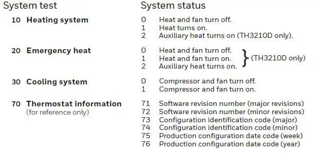
Turn thermostat over to find model number and date code.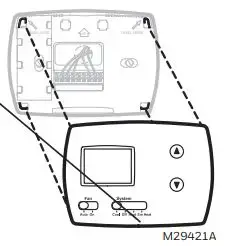
CAUTION: EQUIPMENT DAMAGE HAZARD
Compressor protection is bypassed during testing. To prevent equipment damage, avoid cycling the compressor quickly.
CAUTION: ELECTRICAL HAZARD
Can cause electrical shock or equipment damage. Disconnect power before beginning installation.
CAUTION: MERCURY NOTICE
If this product is replacing a control that contains mercury in a sealed tube, do not place the old control in the trash. Contact your local waste management authority for instructions regarding recycling and proper disposal.
CAUTION: ELECTRONIC WASTE NOTICE
The product should not be disposed of with other household waste. Check for the nearest authorized collection centers or authorized recyclers. The correct disposal of end-of-life equipment will help prevent potential negative consequences for the environment and human health.
https://customer.resideo.com/en-US/support/residential/codes-and-standards/FCC15105/Pages/default.aspx
www.resideo.com
Resideo Inc., 1985 Douglas Drive North
Golden Valley, MN 55422
69-1929EFS—07 M.S. Rev. 08-20 | Printed in United States
© 2020 Resideo Technologies, Inc. All rights reserved.
The Honeywell Home trademark is used under license from Honeywell International, Inc. This product is manufactured by Resideo Technologies, Inc. and its affiliates. Tous droits réservés. La marque de commerce Honeywell Home est utilisée avec l’autorisation d’Honeywell International, Inc.
Ce produit est fabriqué par Resideo Technologies, Inc. et ses sociétés affiliées. Todos los derechos reservados. La marca comercial Honeywell Home se utiliza bajo licencia de Honeywell International, Inc.
Este producto es fabricado por Resideo Technologies, Inc. y sus afiliados.