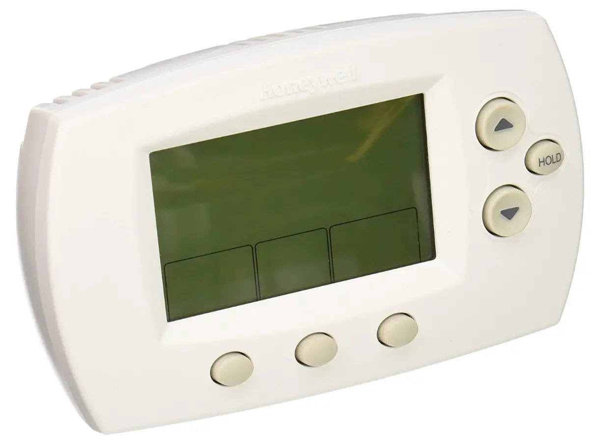

Honeywell TH6110D1005/U Wall Thermostat

Specifications
- Product Dimensions
39.37 x 39.37 x 39.37 inches - Item Weight
0.05 Kilograms - Temperature Ranges
Heat: 40° to 90°F (4.5° to 32°C)
Cool: 50° to 99°F (10° to 37°C) - Operating Ambient Temperature
32° to 120°F (0° to 48.9°C) - Shipping Temperature
-20° to 120°F (-28.9° to 48.9°C) - Operating Relative Humidity
5% to 90% (non-condensing) - Power Source
Battery Powered - Controller Type
Push Button - Material
Attribute not applicable for the product - Control Method
Touch - Backlight
Yes - Control Type
Button Control - Shape
Curved - Number Of Pieces
1 - Display Style
LCD - Brand
Honeywell
Introduction
This thermostat provides electronic control of 24 VAC single-stage heating and cooling systems, or 750 mV heating systems.
System Types
- Gas, oil, or electric heat with air conditioning
- Warm air, hot water, high-efficiency furnaces, heat pumps, steam, gravity
- Heat only — two-wire systems, power to open and close zone valves (Series 20), and normally open zone valves
- Heat only with a fan
- Cool only
- 750 mV heating systems
Power Options
- Battery power only
- Common wire only
- Common wire with battery backup
Changeover Options
- Selectable manual or auto-changeover modes
System Settings
- Heat, Off, Cool, Auto
Fan Settings
- Auto, On
Must be installed by a trained, experienced technician
- Read these instructions carefully. Failure to follow these instructions can damage the product or cause a hazardous condition.
- Check the ratings in this booklet to verify that this product is suitable for your application (see page 13).
- Always test for proper operation after installation (see page 9).
CAUTION
ELECTRICAL HAZARD
Can cause electrical shock or equipment damage. Disconnect power before beginning installation.
MERCURY NOTICE
If this product is replacing a control that contains mercury in a sealed tube, do not place the old control in the trash. Contact your local waste management authority for instructions regarding recycling and proper disposal
Installation tips
Install the thermostat about 5 feet (1.5m) above the floor in an area with good air circulation at average temperature.
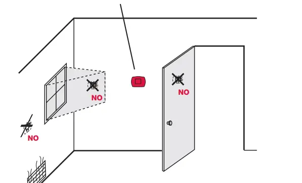
Do not install in locations where the thermostat can be affected by
- Drafts or dead spots behind doors and in corners
- Hot or cold air from ducts
- Sunlight or radiant heat from appliances
- Concealed pipes or chimneys
- Unheated/uncooled areas such as an outside wall behind the thermostat
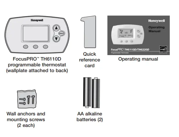
Pre-installation checklist
Package contents
Check to make sure your package includes the following items
Required tools and supplies
- No. 2 Phillips screwdriver
- Small pocket screwdriver
- Drill
- Drill bit (3/16” for drywall, 7/32” for plaster)
- Hammer
- Pencil
- Electrical tape
- Level (optional)
Wallplate installation
Insert finger into wire hole and pull to remove wallplate from thermostat.
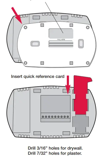
Remove the wallplate from the thermostat as shown on the left, then follow the directions below for mounting.
- Insert quick reference card in a slot in back of the thermostat
- Pull wires through the wire hole.
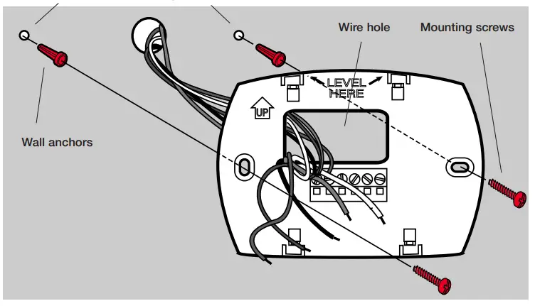
- Position wallplate on wall, level and mark hole positions with a pencil.
- Drill holes at marked positions as shown below, then tap in supplied wall anchors.
- Place wallplate over anchors, insert and tighten mounting screws
Wiring
CAUTION
ELECTRICAL HAZARD. Can cause electrical shock or equipment damage. Disconnect power before wiring.
NOTES
R & Rc terminals
In a single-transformer system, leave a metal jumper in place between R & Rc. Remove the metal jumper if a two-transformer system.
C terminal
The C (common wire) terminal is optional when the thermostat is powered by batteries.
W (O/B) terminal
If the thermostat is configured for a heat pump in the Installer Setup, configure the changeover valve for cool (“O” factory setting) or heat (“B”).
Wire specifications
Use 18- to 22-gauge thermostat wire. A shielded cable is not required.
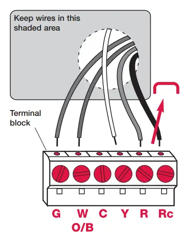
Wiring
- Loosen screw terminals, insert wires into the terminal block, then re-tighten screws.
- Push excess wire back into the wall opening. Keep wires in the shaded area as shown on left.
- Plug the wall opening with nonflammable insulation to prevent drafts from affecting thermostat operation.
Terminal Designations
- G Fan relay.
- W O/B Heat relay or changeover valve terminal for heat pumps.
- C Common wire from the secondary side of the cooling system transformer.
- Y Compressor contactor.
- R Heating power. Connect to the secondary side of the heating system transformer.
- Rc Cooling power. Connect to secondary side of cooling system transformer
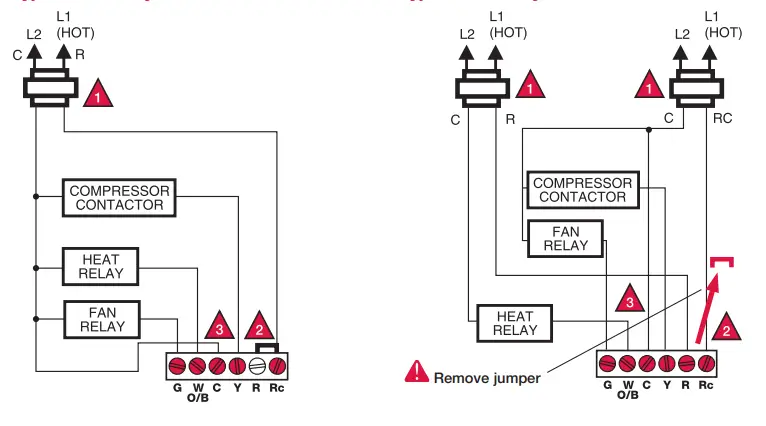
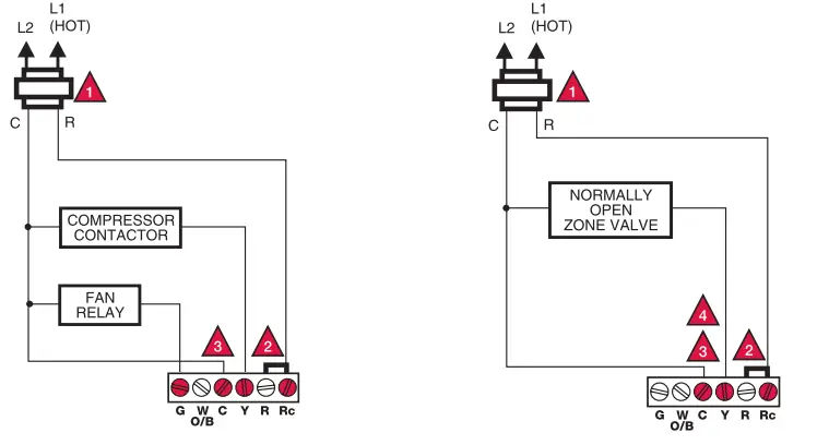
Wiring diagrams
- Power supply. Provide disconnect means and overload protection as required.
- Factory-installed jumper. Remove for 2-transformer systems only.
- Optional 24VAC common connection.
- In Installer Setup, set system type to Heat Only.
- In Installer Setup, set system type to Heat Pump & changeover valve to 0 or B.
Typical 1H/1C system: 1 transformer Typical 1H/1C system: 2 transformers
Typical 1H/1C heat pump system Typical heat-only system
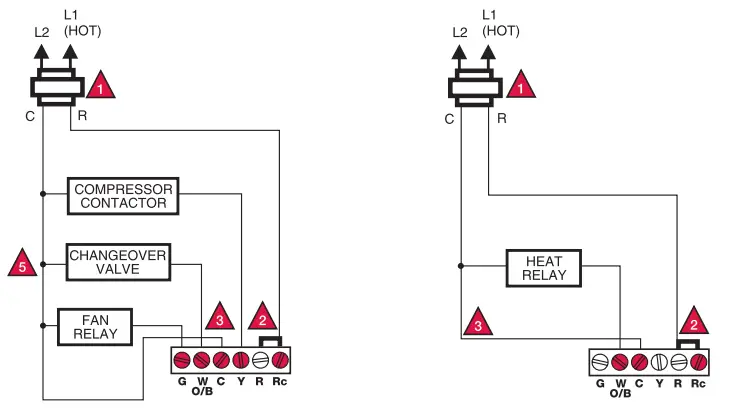
- Power supply. Provide disconnect means and overload protection as required.
- Factory-installed jumper. Remove for 2-transformer systems only.
- Optional 24VAC common connection.
- In Installer Setup, set system type to Heat Only.
- In Installer Setup, set system type to Heat Pump & changeover valve to 0 or B.
Typical heat-only system with fan Heat-only system (Series 20)
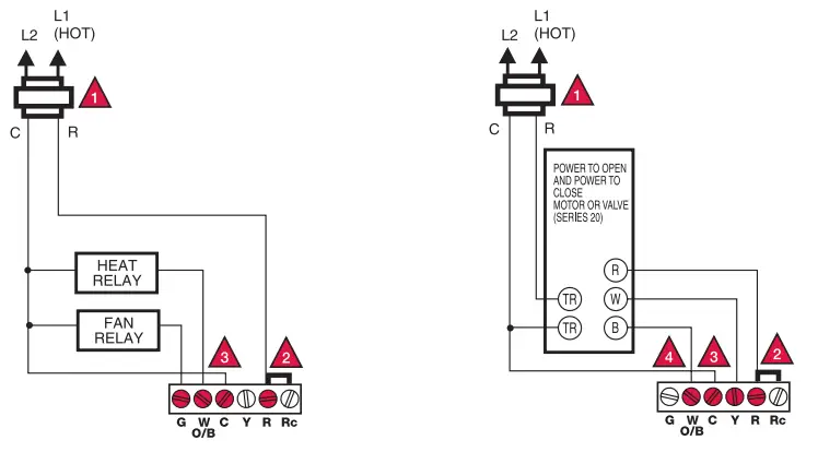
Typical cool-only system Heat-only system (normally open zone valve)
Power options and mounting
AC Power
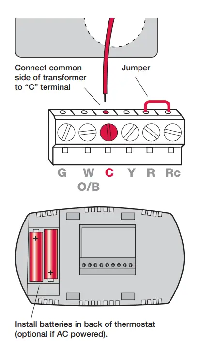
The thermostat can be powered by 24 VAC power, or by batteries. To wire the thermostat for AC power, connect the common side of the cooling transformer to the “C” terminal as shown at left.
Important
Remove R/Rc jumper for 2-transformer systems only. (See wiring diagram on page 5.)
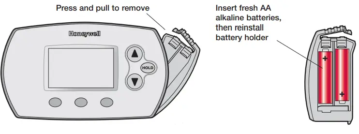
Battery Power
The thermostat can be powered by batteries alone or, if used with AC power, can provide backup power. During power interruptions, the batteries will save time/day settings and power the display.
After installation, batteries can be changed without removing the thermostat from the wall (see page 11).
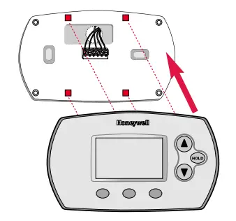
To Mount Thermostat
Align the 4 tabs on the wallplate with corresponding slots on the back of the thermostat, then push gently until the thermostat snaps in place.
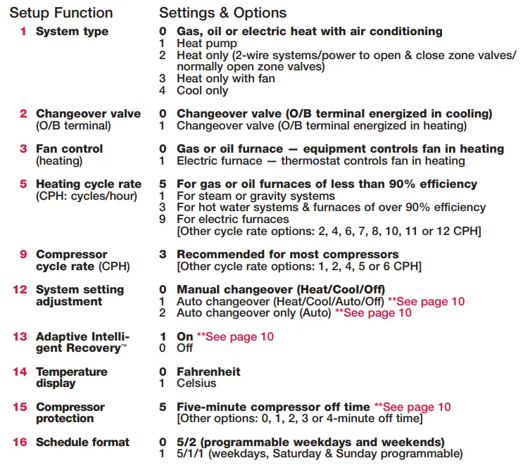
Installer setup
Follow the procedure below to configure the thermostat to match the installed heating/cooling system, and customize feature operation as desired.
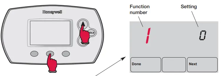
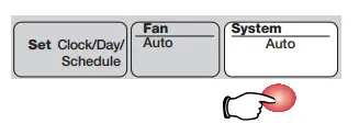
To begin, press and hold the FAN buttons until the display changes
- Press or to change settings
- Press NEXT to advance to the next function
- Press DONE to exit and save settings
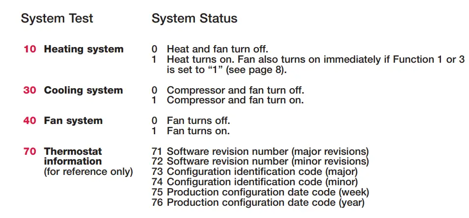
Installer system test
Follow the procedure below to test the heating, cooling, and fan.
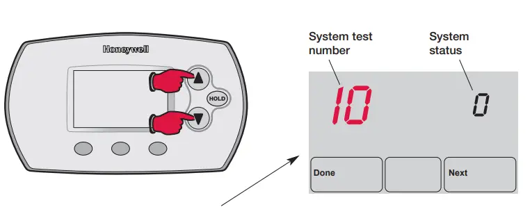
To begin, press and hold the buttons until the display changes.
- Press to turn on the system
- Press to turn off the system
- Press NEXT to advance to the next test
- Press DONE to terminate the system test
CAUTION
EQUIPMENT DAMAGE HAZARD
Compressor protection (minimum off time) is bypassed during testing. To prevent equipment damage, avoid cycling the compressor quickly.
Auto Changeover (Setup Function 12)
- Auto Changeover is a feature used in climates where both air conditioning and heating are used on the same day.When the system is set to Auto, the thermostat automatically selects heating or cooling depending on the indoor temperature.
- Heat and cool settings must be at least 3 degrees apart.The thermostat will automatically adjust settings to maintain this 3-degree separation (called “Deadband”).
- The 3-degree separation between heating and cooling set temperatures is fixed, and cannot be changed.
Adaptive Intelligent Recovery™ (Setup Function 13)
- Adaptive Intelligent Recovery eliminates guesswork when setting your schedule. It allows the thermostat to “learn” how long your furnace and air conditioner take to reach the temperature you want.
- Just set your program schedule to the time you want the house to reach your desired temperature.The thermostat then turns on the heating or cooling at just the right time to reach your scheduled temperature at your scheduled time.
For example
Set the Wake time to 6 am, and the temperature to 70°.The heat will come on before 6 am, so the temperature is 70° by the time you wake at 6.
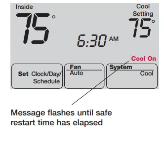
Built-in compressor protection (Setup Function 15)
- This feature helps prevent damage to the compressor in your air conditioning or heat pump system.
- Damage can occur if the compressor is restarted too soon after shutdown.This feature forces the compressor to wait for a few minutes before restarting.
- During the wait time, the message Cool On or Heat On (heat pumps only) will flash on the display. When the safe wait time has elapsed, the message stops flashing and the compressor turns on.
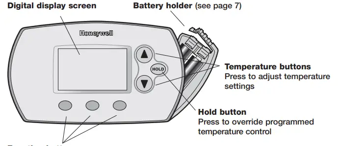
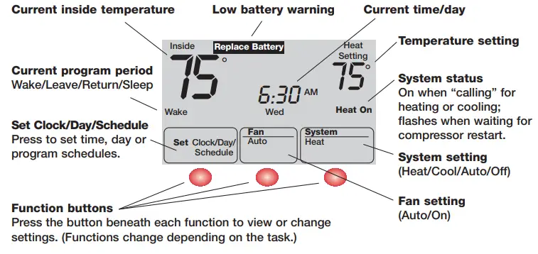
Quick reference to display screen
Battery replacement
In case of difficulty
If you have difficulty with your thermostat, please try the suggestions below. Most problems can be corrected quickly and easily.
Display is blank
- Check the circuit breaker and reset if necessary.
- Make sure power switch at heating & cooling system is on.
- Make sure the furnace door is closed securely.
- If thermostat is battery powered, make sure fresh AA alkaline batteries are correctly installed (see page 7)
Temperature settings do not change
Make sure heating and cooling temperatures are set to acceptable ranges:
- Heat: 40° to 90°F (4.5° to 32°C).
- Cool: 50° to 99°F (10° to 37°C).
The heating system does not respond (“Heat On” appears on screen)
- Check for 24 Vac at the equipment on the secondary side of the transformer between power and common. If voltage is not present, check the heating equipment to find the cause of the problem.
- Check for 24 Vac between the heat terminal (W) and the transformer common. If 24 Vac is present, the thermostat is functional. Check the heating equipment to find the cause of the problem.
- Check for loose or broken wires between the thermostat and the heating equipment.
The cooling system does not respond(“Cool On” appears on screen)
- Check for 24 Vac at the equipment on the secondary side of the transformer between power and common. If voltage is not present, check the cooling equipment to find the cause of the problem
- Check for 24 Vac between the cooling terminal (Y) and the transformer common. If 24 Vac is present, the thermostat is functional. Check the cooling system to find the cause of the problem.
- Check for loose or broken wires between the thermostat and the cooling equipment.
The fan does not turn on in a call for heat
- Check Installer Setup, Function 3 (Fan Control), to make sure the fan control is properly set to match the type of system (see page 8).
Heat pump issues cool air in heat mode, or warm air in cool mode
- Check Installer Setup, Function 2 (Changeover Valve), to make sure it is properly configured for your system (see page 8).
Heat/cool both on at the same time, or heat does not turn off
- Check Installer Setup, Function 1 (System Type), to make sure it is set to match the installed heating/cooling equipment (see page 8).
- Check to make sure heating and cooling wires are not shorted together.
Heating equipment is running in cool mode
- Check Installer Setup, Function 1 (System Type), to make sure it is set to match the installed heating/cooling equipment (see page 8)
Cannot change system set to “Heat”
- Check Installer Setup, Function 1 (System Type), to make sure it is set to match the installed heating equipment (see page 8).
- Change Installer Setup, Function 12 (System Setting) to Manual or Auto Changeover (see page 8).
Cannot change system set to “Cool”
- Check Installer Setup, Function 1 (System Type), to make sure it is set to match the installed cooling equipment (see page 8).
- Change Installer Setup, Function 12 (System Setting) to Manual or Auto Changeover (see page 8).
“Heat On” is not displayed
- Change the System Setting to Heat, and set the temperature level above the current room temperature.
“Cool On” is not
- Change the System Setting to Cool, and set the temperature level below the current room temperature.
“Cool On” or “Heat On” is flashing
- Compressor protection timeout is engaged. Wait 5 minutes for the system to restart safely, without damage to the compressor.
Accessories and replacement parts
Please contact your distributor to order replacement parts
- Battery holder ………………………………………………Part Number 50007072-001
- Cover plate assembly ………………………………….Part Number 50002883-001
(Use to cover marks left by old thermostats.)
Frequently Asked Questions
Does this product auto-switch between cool and heat?
Yes, but it must be configured to do so. If you see only “heat/cool/off” in the mode screen, then press “fan” and “up” simultaneously. When the screen changes, press “next” until you reach option 12. Setting “0” enables “heat/cool/off” in the mode screen, while setting”1″ enables “heat/cool/auto/off.” Setting “3” is “auto/off” only. When you press “done,” your mode screen will show the option you selected. FYI: In “auto” mode, the “heat” temperature at any time must always be at least 3 degrees less than the “cool” temperature.
Can the 6000 be used with two heat and one cool?
the answer is in the product number. 6110 does 1 heat & 1 cool. 6220 does 2 heat and 2 cool, 6320 does 3 heat and 2 cool.
I have an electrical heat/cool pump that has emergency heat. Does this work with my model?
This model does not have terminal strip connections for emergency/auxiliary heat. The TH6220D has additional functionality for emergency/auxiliary heat. See instructions for 1C/2H installations.
Do you need to turn off the power before installing the FocusPro 6000?
Yes, you want to turn off power at the furnace. If the thermostat wires touch each other it can blow a fuse in the furnace.
How do you open the unit to change its batteries?
I clicked on the “no image available” and it took me to the Honeywell FocusPRO 6000 Programmable Thermostat. I love this thermostat because the batteries are so easy to replace. Do not remove it from the wall. I automatically did the first time. It is sooo simple – the battery compartment is on the upper right side. You push down on the compartment where it is marked “press,” rotate it a little to the right, and pull the battery compartment out
Can I change the temperature differential? currently, it is +/- 1f. can i update it to +/- 3f? if so, how can i do it?
They are asking if you can change the tolerance so the heat or air doesn’t come on as often. I would like to know the answer as well.
Can you pause the daily program easily in the event you are home unexpected time?
It is easy to exit the program and use manual temp settings from the unit. And from the mobile app it is easy to pause, cancel or edit the schedule.
Is the power source electrical or battery?
It is powered by the furnace and has a battery backup to maintain all the settings.
Can it use on bms controlled by pc?
This is not a wifi unit. Honeywell has wifi in a different model
Compatible with only 4 wires coming from the wall?
Yes, if you only have 4 wires, that means the thermostat will run off battery power alone.
Does it work on heat pump?
Yes, it works with heat pumps or electrical furnaces. However, note: the thermostat comes with defaulted preset settings for gas and oil furnaces! I almost sent mine back. But online searches: someone mentioned reading the installation instructions to change. Holding the center fan and arrow up buttons for about 5secs together. And go to Function 3, change from 0 to 1 sets. Done
I have an American standard acont600af11ma that is not produced anymore. can i sub it with this one? it look like this one on the pic
Main thing to check is correct wiring to run your fan manually or not. The one I chose allows me to run my fan without heat or air conditioning since I use to circulate house heat from my wood stove. G
Does this unit work with electric baseboard heaters?
No it doesn’t. Baseboard heaters take a special thermostat.
Can a temperature sensor be hardwired into it?
The thermostat works fine as intended. I have not tried to modify it.
I need a programmable thermostat that you can program while sitting at a table and then return it to the base. Is this possible?
Yes, once the batteries are in, you can hold the unit in your hand and program it separately from the base that is mounted on the wall.