YTH8321WF1036/U
Installation Guide [pdf]: VisionPRO 8000 Smart TH8321WF1001 Installation Guide
Product Information [pdf]: VisionPRO 8000 Series
How does the T9/T10 control temperature in one room if you do not have dampers?
When you adjust the temperature in one room, it will impact the temperature in the rest of your home. For example, if your basement is regularly 4 degrees cooler than your bedroom, it will continue to be slightly cooler as you adjust the temperature to meet your bedroom preferences. If the bedroom and the basement are both selected as priority rooms, the thermostat will average the temperature of those two rooms, and your basement will still be cooler than your bedroom.
Tell me about the difference between the T9/T10 Smart Room Sensors and a zoned HVAC system
The thermostat uses up to 20 wireless sensors to read temperatures in multiple rooms of your home. Based on your preferences, the thermostat can read from, and average, these multiple sensors and the thermostat. The T9 and T10 Smart Thermostat will calculate the average of the temperatures detected in all selected or active rooms to deliver the best temperature to your whole home. In this way, the T9 and T10 Smart Thermostats work with the sensors to make you feel closer to your desired temperature, wherever you are in the home.
While the T9 and T10 thermostat can better fine-tune your comfort in your home, it’s important to distinguish that no thermostat alone, regardless of sensors, can maintain separate temperatures in different rooms without air dampers or smart vents.
For homes that already utilize a zoning solution, such as a zone control board or duct dampers, Smart Room Sensors can still help further increase comfort and savings by providing a more accurate reading of the temperature in each zone. A T9 or T10 Smart Thermostat would be required for each zone being controlled, and each thermostat will require its own sensors, based on your desired level of control. Smart Room Sensors cannot connect with more than one thermostat.
If you have any questions about whether or not the T9 and T10 Smart Thermostat is the best option for your home, you can contact our support team or find a local pro.
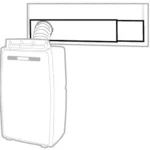
The Honeywell Whole-House Ventilation System removes stale air and replaces it with fresh air. A centrifugal blowers brings fresh air into your home from outdoors and at the same time exhausts the stale air in an equal amount. Both the incoming and outgoing air streams pass through an exchange core where the energy from the exhaust air is efficiently transferred to the incoming air. In the winter, this means that the fresh air coming into the house is warmer than the cold air outdoors. In the summer, this means that the fresh air coming into the house is not as hot as the air outdoors. Vents in your home draw the stale air into the Honeywell Whole-House Ventilation System to be exhausted outside. After the heat and energy is exchanged, the fresh air brought in through the ventilator gets distributed in the house though the ducts of your heating or cooling system.
A Heat Recovery Ventilator (HRV) saves energy by transferring heat between the stale air exhausted to the outside and the fresh air that is brought inside. This makes sure that when the ventilator is bringing in outside air, the heat stays inside the house in the winter or outside the house in the summer. The Energy Recovery Ventilator (ERV) saves energy by transferring both heat and moisture. Both the HRV and the ERV are Honeywell Whole-House Ventilation Systems that provide the ventilation and allow you to save energy. Check with your local contractor to find out which one is right for you.
Only the (Professional model) TH6320WF2003/U (Wi-Fi) model uses these terminals. The TH6320WF2003/U can be configured to control a whole house ventilator or an EARD fresh air damper for ventilation.
Only the (Trade model) TH6320WF2003/U (Wi-Fi) model uses these terminals. The TH6320WF2003/U can be configured to control a whole house ventilator or an EARD fresh air damper for ventilation.
The size of the HRV or ERV depends on many factors including the size of your home, the number of people in your home, and whether you are ventilating special use rooms (such as bathrooms or laundry rooms). A local heating and cooling contractor can assist you in choosing the correct Honeywell Whole-House Ventilation System for your home.
Yes, your Lyric thermostat can control a whole home ventilator or ventilate your home by circulating your air.
The Lyric is able to manage a wide range of climate control systems to maximize your comfort, including your heating and cooling systems as well as other indoor air quality (IAQ) systems, such as a whole house humidifier or dehumidifier or ventilation system. The U wire terminals are used to control indoor air quality equipment. Refer to the wiring configuration on your previous thermostat to wire your Lyric properly to your whole house humidifier or dehumidifier or your ventilation system.
In some cases, your IAQ system may be controlled by a separate panel, not by your old thermostat. If so, consult your contractor for advice on connecting that system to your Lyric. For a list of contractors trained to assist in Lyric installation and configuration, go here.
Alternatively, if you have installed the Lyric app on your mobile device, go to the home screen and tap the three vertical dots icon in the upper right hand corner. Tap “Contractor Information” and select your location for a list of local approved contractors.
Yes, you will need to have Wi-Fi to control your ventilation. This feature is managed through the Lyric app, which requires Wi-Fi connectivity.
Only the (Professional model) TH6320WF2003/U (Wi-Fi) model uses these terminals. The TH6320WF2003/U can be configured to control a whole house ventilator or an EARD fresh air damper for ventilation.
Only the (Trade model) TH6320WF2003/U (Wi-Fi) model uses these terminals. The TH6320WF2003/U can be configured to control a whole house ventilator or an EARD fresh air damper for ventilation.
*There is no standard for which color wire controls each function. When wiring, each wire should be identified by what terminal(s) it connects to, never by color. If you do not know the terminal that each wire connects to, it may be necessary to go to the HVAC system and look at the designations on the control board. For typical wiring examples, and for clarification of what types of systems your thermostat works with, please consult your owners/install guide. *
The thermostat uses 1 wire to control each of your HVAC system’s primary functions, such as heating, cooling, fan, etc. See the diagram below for what each wire controls on your system:
S – Indoor and Outdoor Wired Sensors
Y – Compressor Stage 1 (Cooling)
Y2 – Compressor Stage 2 (Cooling)
G – Fan
C – Common
U – Humidifier, Dehumidifier, or Ventilator control
L/A – A – Input for heat pump fault
O/B – Reversing valve for Heat Pump systems
E – Emergency Heat
Aux / W2 – Heat Stage 2 (Heating)
W – Heat Stage 1 (Heating)
R – 24vac (Heating transformer)
Rc – 24vac (Cooling transformer)
*Trade model thermostats are required to operate “dual-fuel” systems (systems that use a heat pump for the first 1 or 2 stages of heating and use a gas or oil furnace for backup / emergency heating). If you have a dual-fuel system, or are unsure, it is recommended that you contact a Professional HVAC Contractor to continue.
Please follow the below guide for the basic wiring walkthrough:
To protect your equipment, turn off the power at the breaker box or switch that controls your heating and cooling equipment. To make sure that your system is off, change the temperature on your existing thermostat so that your system starts heating or cooling. If you don’t hear or feel the system turn on within 5 minutes, the power is off. If you have a digital thermostat that has a blank display, you can skip this step.
Next, remove your existing thermostat from the wall plate. Most thermostats pull directly off the wall. However, some lift from the bottom and lever off, and others have a locking tab.
The next step is to take a picture of your wiring. When taking the picture, please make sure that the terminal markings are clearly visible.
Review your pictures.
If you see terminals labeled A B C, or 1 2 3 then your new thermostat may not be directly compatible, as your system requires a communicating thermostat.
If you see thick, black or red wires then you have a line voltage system. This type of wiring requires a line voltage thermostat and is not compatible with low voltage thermostats
If you see wires connected to terminals labeled G1,G2,G3, you will need a thermostat capable of controlling multiple fan speeds, none of our retail thermostats are compatible with this system type. G is compatible, but not G1,G2,and/or G3.
What you should typically see is 18 – gauge solid core wire. The most common configuration is five wires, however you could see as few as two, and as many as ten.
Any wire that is present, but not connected to a terminal you will want to make a note of, but you will not label these wires.
Using the photos that you took, remove each wire one at time and label it. If a terminal has multiple designations like W and O/B, it will be labeled as W and O/B and not just one or the other.
After you have removed and labeled all wires you can unscrew, remove the old thermostat wall plate and mount the new thermostat’s wall plate.
After mounting the new thermostat’s wall plate, we can re-connect the wiring. If we recommend placing a wire in a terminal, do not move it to another terminal if we address it later in the guide. (Ex. – You have a single wire labeled W-O/B and we advise placing it in the O/B terminal. If later in the guide we recommend putting the W wire in the W terminal, you will not move this wire, as we’ve already instructed you to place it in O/B.)
Now, let’s cover wiring configurations.
Identify any wires label R, RH, or RC. You will typically have one or two out of those three. If you just have one wire, regardless if it’s labeled RC, it will go into the R terminal, and the jumper connecting terminals R and RC will be in place. Some thermostats have a jumper switch, some have a metal staple, others may have a plug, and the jumper may also just be a wire connecting the two terminals. If you have two wires, R or RH will go into the R terminal, and RC will go into the RC terminal. If you have more than one wire (you have a wire labeled R, and another wire labeled Rc for example) you can remove any jumpers between the R and Rc terminals, or push the switch to open the RC terminal so you can insert a wire.
Next, let’s talk about the C, or common wire. If you have a Trane model thermostat, and have a wire labeled X or B refer to your thermostat manual. In some cases, one of those wires may be your common. If you have a C wire, place it into the C terminal on your wall plate.
Let’s take a look at the G wire. This wire will go to the G terminal on your new thermostat.
For the Y, Y1, and Y2 wires, Y or Y1 will go to the Y terminal, and Y2 will go to the Y2 terminal.
The O/B wire can have many configurations. It can be W-O/B, O/B, W-O, W-B, or you may even have separate O and B wires. If you have separate wires for O and B, you will want to tape off the B wire so it can’t make contact, and the O wire will be connected to the O/B terminal on your thermostat.
If your O or B terminal shares a label with another wire, typically W, you’ll need to identify whether you have a heat pump system or not. A heat pump runs your compressor for both heating and cooling. If you don’t know your system type, place this wire into the W terminal. If you have a heat pump system, place it into the O/B terminal.
Locate any unconnected wire labeled W or W1. If in the previous step you identified an O, B, or O/B wire that’s connecting to the O/B terminal, and have a separate W wire, place this wire into the W2 terminal. If you do not have a wire connected to the O/B terminal, connect the W wire to the W terminal.
Specifications
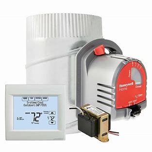
Fresh Air Ventilation Kit With 6 In. Damper
| Building Square Footage (Max) | 4600 |
| Warranty | 5 Years |
| Includes | TH8321WF1001 Wi-Fi VisionPRO® 8000, EARD6TZ TrueZONE Fresh Air Damper,, AT120B1028 24V Transformer |
| Product Height | 4.63 in |
| Product Length | 1.13 in |
| Product Width | 4.94 in |
| Color | Arctic White |