![]()
LA400EV

Automatic Gate Opener*
*For GB (UK, NI) specific information on national regulations and requirements see English part of the manual.
NOTE: The original installation and operating instructions were compiled in Germany. Any other available language is a translation of the original Germany version.
General Safety Guidelines
![]()
![]()
![]()
![]()
![]()
![]()
![]()
![]()
![]()
![]()
![]()
![]()
![]()
Content
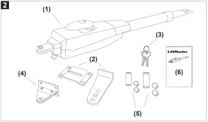
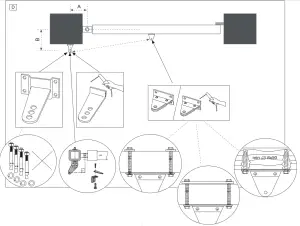
- Motor LA400EV (1x)
- Postbracket (1x)
- Key (2x)
- Gate fixing bracket (1x)
- Clevis pin (2x) and rings (4x)
- Manual (1x)
BEFORE YOU BEGIN
The drive mechanism needs room to the side permitting correct installation of drive arms. Please make sure that this is available. Gates affected by high wind loads must also be protected by an (electric) lock.
There are many factors to consider when choosing the right drive mechanism. Assuming that a gate functions properly, „startup“ is the most difficult phase, once the gate
is in motion, significantly less force is usually required to move it.
- Gate size: Gate size is a very important factor. Wind can break or distort the gate, thereby increasing the amount of force needed to move it considerably.
- Gate weight: The weight of the gate in not as relevant as the size.
- Effect of temperature: Low outdoor temperatures can make initial startup more difficult (changes in the ground, etc.) or even prevent it.
- Duty cycle: 24-volt drives can run permanently.
INSTALLATION CHECKLIST – PREPARATIONS
Check the carton contents and read the instructions carefully. Make sure your gate equipment operates perfectly. The gate must run evenly and smoothly and must not stick at any point. Remember that the ground level may be several centimeters higher in winter. The gate must be stable and as free of backlash as possible in order to prevent any unwanted to and fro movement. The more smoothly the gate leaf runs, the more sensitive the force adjustment must be.
Note down any materials you still need and obtain them before starting to install. Heavy-duty plugs, bolts, gate stops, cables, distribution boxes, tools, etc.
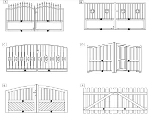
Gate Types
The gate type determines the location where the drive mechanism is installed. If the gate stop is on the ground, the drive mechanism must also be installed at a height that is as low as possible so that it cannot twist the gate. Use only parts of the gate frame for fixing purposes.
TYPE A, B, C
For steel gates, the gate fitting must be attached to the mainframe. If you are uncertain whether the available support is sufficiently stable, reinforce it.
TYPE D, E, F
In the case of wooden gates, the gate fitting must be through-bolted. It is advisable to fit a plate from the outside so that the fixing brackets cannot become loose over time. Thin wooden gates must also be reinforced in order to withstand the stresses encountered (e.g. type F).
Gate Configuration
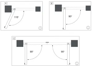
How far must the gate leaf open?
90 degrees or up to 115 degrees. An opening angle in excess of 115 degrees is possible to a limited extent but is not recommended. Reason: the drive mechanism always
runs at the same speed. The further the gate has to be opened, the faster the gate leaf must travel. Movement becomes more erratic and this subjects the fittings and gate to
extreme stresses.
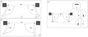
For gates without limit switches: Non-identical opening angles cause one drive mechanism to reach its destination first, but continue to run, thereby forcing the gate up against the gate stop until the other motor eventually reaches its end position (see figure 4A-F).
Tip for professionals: The time taken to reach the limit stop can be controlled by deliberately selecting different A and B dimensions (left + right). However, this method of installing subjects the fittings to high stresses and can cause the gate to run erratically. It is recommended that only experienced gate installers adopt this method.
NOTE: If the gate opens towards a wall, there is a risk of entrapment. Should the distance between the wall and the open gate be less than 200 mm, this area must later be secured via a light barrier or contact strip.
Gate Stops
It is advised to use a fixed gate stop in both the open and close directions. Gate stops save wear and tear on the drive mechanism, gate, and fittings. Operating a gate without fixed limit stops results in poor performance. It is often dangerous, leads to premature wear, and voids your warranty!
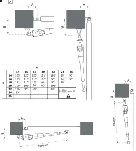
Post Fixing Bracket
Choosing the correct location for the post-fixing bracket has a decisive impact on the subsequent functioning of the system. It determines the distance between the motor‘s entre of motion and the gate‘s center of motion and hence the opening angle. These dimensions are referred to as dimension A and dimension B. Do not underestimate the effect that these dimensions have on correct functioning and running. Try and achieve the best dimension for your opening angle, as precisely as possible and suitable for all
circumstances.See Table (figure 5A) for dimensionsA/B.
If the post is not wide enough, an extension piece must be fitted to it (figure 6B). If the post is too thick, cut out part of it to make it thinner (figure 6D)or offset the gate (figure 6C).
To obtain ideal dimensions, it may be necessary to shorten or lengthen the supplied hinge plate. In the case of gates that are to be custom made, if the gate hinges are fitted on the posts appropriately, it is possible to influence dimensions A and B. Before the final mounting dimensions are determined, you should always check whether or not there is any possibility that the corner of the drive mechanism will hit the post as the gate swings.
INSTALLATION: The drive mechanism exerts a considerable force against the post. Usually, acceptable mounting dimensions are obtained if the supplied hinge plate is welded directly onto the post. In the case of thick stone or concrete posts, the hinge must be welded to a base plate and attached so that the plugs cannot work loose during operation. Heavy-duty plugs where a threaded rod is bonded into the masonry stress-free are more suitable for this purpose than steel or plastic straddling plugs. In the case of brickwork pillars, bolt on a relatively large steel plate that covers several bricks and then welds the hinge plate to it. An angle plate attached over the corner of the post is also a good means of fixing the operators.
Gate Fitting
The gate fitting must be installed so that it is horizontal relative to the post bracket. The distance between the gate bracket and post bracket is referred to as the „arm span“. When the gate is closed, the drive mechanism is 99% extended. When the gate is opened, the drive mechanism is 1% extended. Fully retracting or extending the lunger/spindle in operation (with gate) damages the drive mechanism and voids the warranty. It is absolutely imperative to comply with the required arm span under all circumstances! For steel gates, fixings should be welded on or through-bolted. When bolting the gate, use large washers or a plate on the other side. The drive mechanism exerts an extremely high force on this joint. Fixings must be through-bolted for wooden gates. Wood deflects under load and the bolt will become loose. Due to movement caused by repeated loading, the wood deflects more and more until the gate no longer closes correctly and has to be repaired. Fit a reinforcing plate from the outside and one on the inside so that the wood cannot deflect and the joint cannot become loose. Thin wooden gates without a metal frame must also be reinforced in order to withstand continuous stresses (e.g. type F).
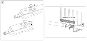
Release
The drive mechanism can be released. The gate can then be opened and operated manually (power failure). With a new drive mechanism, the release action may sometimes feel stiff/jerky. This is normal and has no effect on function.
Release: Insert the key in the cylinder lock and turn it 180 degrees. Then turn the release lever 180 degrees – done!
Engage: Turn the lever glockwise. As soon as the gate moves or the drive runs, the gear locks again. Use the lock to protect the liver against unauthorized release.
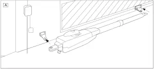
Installing The Drive Arm
Release the drive. Push the released drive onto the fittings and secure it by using the supplied bolts, nuts, and rings. „If the center or inner hole, on the hinge plate, is used to fix the post fixing bracket you MUST cut away the remaining section of the hinge plate before activating the arms. Failure to do so will result in breaking the fixing bracket“. Do not use a hammer when you mount the operator on the bracket.
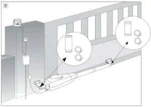
Wiring
The connecting cable has 6 wires, is approx. 3 m long and is run in a curve to the control unit or to a watertight distribution box located above ground. A permanent connection is formed from the distributor box via an appropriate cable.
Connection: See control unit instructions.
Cable colors: Brown/Green/White/Yellow=sensors
Blue/Red: 24-volt motor.
ACCESSORY TIP: Extension cable LA400-JB40
Contains:
(1) 12m cable with terminals
(1) Distribution box IP65
(2) Strain relief PG 13,5
(1) Mounting material
Initial Operation
Check functionality in a disengaged state with the hand on the gate. Initial electrical operation is only possible with a suitable control unit that can be purchased as accessory. Ensure at all times that mechanical and electrical safety instructions applying to the given installation are complied with.
Should the force of the moving wing at its closing edge be higher than 400N, then additional safety facilities (light barrier, contact strip) must be used. Any safety facilities must comply with the requirements set out in EN60335-2-103
Maintenance Work
The drive mechanism is maintenance-free. Check that the gate fittings and the drive mechanism are securely fixed at regular intervals (monthly). Release the drive and check that the gate functions properly. Unless the gate runs smoothly it will not operate correctly with the drive mechanism. The drive cannot eliminate the problems caused by a gate that does not work satisfactorily.
NOTE: also see owners manual of Electronic Control
Disposal

Technical Data
| Motor Voltage | 24 Volt |
| Current consumption | 2:00 AM |
| Power consumption | 48 W |
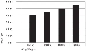
| Max. gate width | 4,0 m |
| Max. gate weight | 250 kg |
| Protection Class | I – IP44 |
| Force (nominal) | 250 N |
| Travel Speed | variable |
| Opening time 90° | 14 sec. |
| Temperature | -20°C to + 55°C |

http://www.liftmaster.eu
Chamberlain GmbH
Saar-Lor-Lux-Str. 19
66115 Saarbrücken
Germany
WEEE-Reg.Nr. DE66256568
www.liftmaster.eu
[email protected]![]()