

-
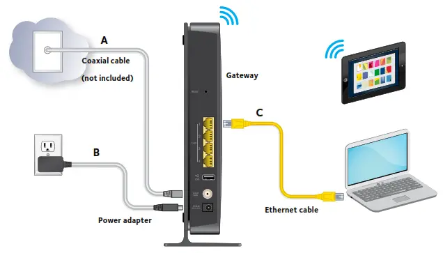
Use a coaxial cable that is provided by your cable company to connect the cable port on the gateway to a cable wall outlet or a line splitter (A).
-
Connect the power adapter to the gateway and plug the power adapter into an electrical outlet (B). The Power LED
 lights green.
 -
Use an Ethernet cable to connect a computer to the Ethernet port on the gateway (C).
You can also connect with WiFi. Use the WiFi network name and password on the product label. -
Launch a web browser.
The gateway menu displays.
If you do not see the gateway menu, enter http://routerlogin.net or http://192.168.0.1 in the address field of the web browser.
When prompted, enter admin for the user name and password for the password. -
Download the free genie app from www.NETGEAR.com/genie.
Easily share media and files on the network from your smartphone, tablet, or laptop.
You can use the buttons and LEDs on the front of the gateway to check its status.


To connect your computer or WiFi device (such as a smartphone or gaming device) to your gateway’s WiFi network, you can use either the manual method or Wi-Fi Protected Setup (WPS) method.
Contact your cable Internet service provider for technical support.
For the current EU Declaration of Conformity, visit http://support.netgear.com/app/answers/detail/a_id/11621/.
For regulatory compliance information, visit http://www.netgear.com/about/regulatory/.
This reminder is provided to call the CATV system installer’s attention to Section 820-93 of the National Electrical Code, which provides guidelines for proper grounding and, in particular, specifies that the coaxial cable shield be connected to the grounding system of the building as close to the point of cable entry as possible.
: When installing or realigning an outside antenna system, take extreme care to avoid any contact with power lines or circuits. Contact could be fatal.
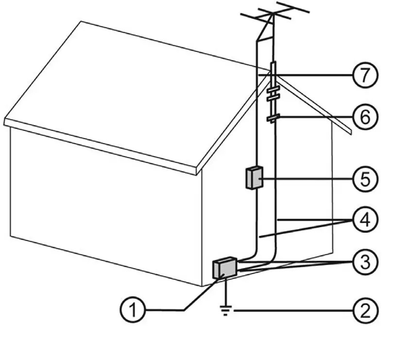
The numbers in the figure on the right indicate the following items:
- Electric service equipment
- Power service grounding electrode system (NEC Art 250, Part H)
- Ground clamps
- Grounding conductors (NEC Section 810-21)
- Antenna discharge unit (NEC Section 810-20)
- Ground clamp
- Antenna lead-in wire
NETGEAR, the NETGEAR logo, and Connect with Innovation are trademarks and/or registered trademarks of NETGEAR, Inc. and/or its subsidiaries in the United States and/or other countries. Information is subject to change without notice. © NETGEAR, Inc. All rights reserved.
NETGEAR, Inc.
350 East Plumeria Drive
San Jose, CA 95134, USA