![]()
Hardwire Kit
User Manual
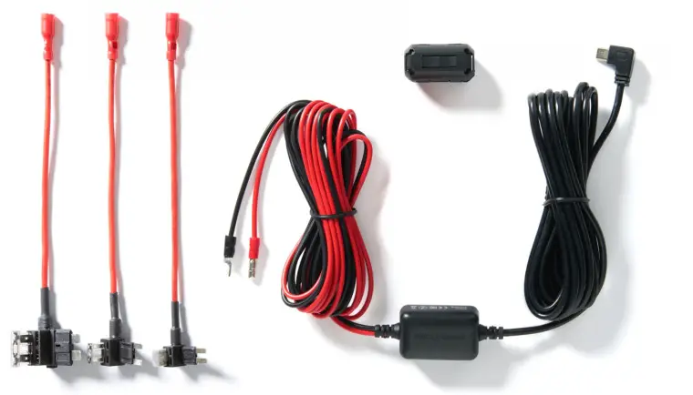
Hardwire Kit
For use with all NextbaseTM Dash Cam models. These instructions provide the necessary information to install the Dash Cam Hardwire Kit properly and safely within your vehicle. Before beginning the installation process, please read these instructions carefully. It is recommended for normal journey video recording, the Hardwire Kit is connected to a switched’ power supply. This means that power is supplied to the Dash Cam ONLY when the vehicle’s ignition is turned on. A permanent live (un-switched) connection is only required when the Dash Cam is to be used when the vehicle is not in use, i.e. for surveillance purposes. The Dash Cam will operate normally until the vehicle’s battery drops below the minimum voltage cut-off level; this minimum voltage cut-off is 11.0Vdc for a 12Vdc battery and 23.0Vdc for a 24Vdc battery. This protects the vehicle’s battery.
 If in any doubt, please consult a vehicle technician prior to starting installation.
Safety Precautions:
- Perform the installation with the ignition in the OFF position.
- Do not strip any live wires.
- Correct electrical polarity and grounding is required for safe and proper installation.
- Only connect to a negative ground DC supply circuit.
- Not for installation to positive ground circuits.
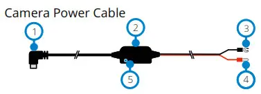
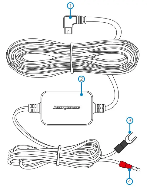
| 1. 5V Mini USB connector 2. 12-24Vdc to 5Vdc regulator 3. Negative (-) spade connector |
4. Positive (+) car power cable bullet connector 5. LED indicator |
Warnings:
- Failure to use the supplied installation parts and/or hardware will void the product warranty.
- Failure to connect the product as instructed may result in discharge of the vehicle battery.
- Failure to follow these safety precautions and instructions could result in damage to the product and/or vehicle, which will not be covered under the product warranty or the manufacturer’s warranty.
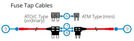
Note: For Micro (Low Profile Mini) Fuses, see item 1.3 overleaf.
Installation
- Connect the supplied ‘Fuse Tap Cable’ to the vehicle’s fuse box.
- Locate the fuse box within your vehicle. This is usually within the passenger compartment but it may be in the engine bay. Typically there will be a chart detailing the fuse layout within the fuse box, or this will be listed in the vehicle operating manual.
- Select a fuse which is associated with a function within the vehicle which can only be used when the ignition is turned on, this is known as ‘switched’ power source. This could be the vehicles ‘heated rear window’, as an example. Mark down the position of this fuse carefully for future reference, remove the selected fuse from the fuse box. Note: The rating of the `original fuse’ that is being removed is of no importance, however it is recommended that the maximum rating is no more than 20 Amps.
- Select the required Fuse Tap Cable from the two supplied types. This depends on whether the original fuse was of the larger ATO/C or smaller ATM type. The 2 Amp fuse required to protect the Dash Cam is already installed within the Fuse Tap Cable and should NOT be changed. Insert the original fuse from the vehicle in to the available location upon the Fuse Tap Cable, this will be the ‘original fuse location’, as shown overleaf. Now insert the Fuse Tap Cable in to the fuse box, at the position where the original fuse was removed from, as noted in Item 1.2 above.
Note: If the fuse removed from your vehicle is a Micro (low profile mini) fuse type, then you can still use the ATM (Mini) fuse tap cable. You will however need to source yourself another ATM (Mini) fuse, of the same rating as the fuse that you removed originally. Place the new ATM (Mini) fuse into the ‘original fuse location’. At this stage, if you have a multi-meter, you can check for 12-24Vdc at the end of the Fuse Tap Cable. A voltage should only be present when the vehicle’s ignition is turned on (or connected to a permanent live). There is an LED on the regulator housing to indicate if the Fuse Tap Cable has been wired correctly (see below).
- Installing the Camera Power Cable
- Installation of the camera power cable needs careful planning for the cable run and the final position of the Dash Cam within the vehicle. See the Dash Cam manual for optimum camera position. Study the vehicle for the most appropriate cable run towards the fuse box, especially if this requires passing through the bulkhead in to the engine bay.
- Starting from the Dash Cam end of the cable (with the mini USB plug) tuck the cable under the vehicle headlining, the `A’ post trim and side panel trim until the cable exits towards the footwell. Use a Cable Tidy Tool supplied with your Series 2 Dash Cam to loosen any trim and hide the cable as necessary. Make sure there is still sufficient cable available to connect to the Dash Cam, when installed correctly upon it’s windscreen mount.
- Continue to route the cable towards the fuse box. Once close to the fuse box, take the black 2 wire (negative) from the Car Power Cable and find a suitable position to attach the spade connector to the vehicle bodywork. Normally a screw can be removed and refitted with the spade connector underneath. Take the red wire (positive) from the Car Power Cable and locate the red bullet connector at the end. This plugs directly in to the female bullet connector of the Fuse Tap Cable.
- Tidy any excess cable using cable clips and secure the cable to a convenient location to prevent rattles. Replace any removed trim from the vehicle and the fuse box cover, as
required. - A Ferrite Core is supplied with the Hardwire Kit. This can be used to suppress any interference which may be heard upon FM or DAB radio. Clip the Ferrite Core to the Camera Power Cable at a distance of approximately 20cm from the camera for best effect, if required.
Note: In the unlikely event that the installation of the Hardwire Kit should require drilling of holes, the installer MUST be sure that no vehicle components or other vital parts could be damaged by the drilling process. Check both sides of the area before drilling begins. De-burr any holes and remove any metal remnants. Install a rubber grommet into any cable passage holes, before passing cables through.
LED Indicator
| If there is no power to the Hardwire Kit the LED will not be turned on. | 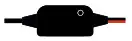 No LED No LED |
No power OR battery protected |
| Once power is flowing to the Hardwire Kit, the Led will turn on. If there is no Dash Cam connected, it will flash |  Flashing LED Flashing LED |
Power established, NO Dash Cam connected |
| If there is a Dash Cam connected, the LED will remain on. | 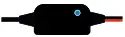 Solid LED Solid LED |
Power established, Dash Cam connected |
Should you experience any difficulties during installation please do not hesitate to contact our technical support team [email protected]
![]()