 RoHS Smart Bracelet User Manual
RoHS Smart Bracelet User Manual
Compatible system and requirement
 Android 4.4 or above
 ios above 8.5 iphone5s
 Bluetooth 4.0
Preparation
Please charge the smart band fully before first use. Charge 1-1.5 hours if the smart band cannot turn on. The smart band are unable to use while in charging mode. 
![]() Note : If the equipment is not used for a long time, make sure to charge the bracelet once every 3 months.
Note : If the equipment is not used for a long time, make sure to charge the bracelet once every 3 months.
Connection Instruction
Download the App
- Method1 : Scan the code below to download the APP.
- Method2: Please ensure the bluetooth is on,and open “Wearfitr”.Click the selection of link to bracelet,find the device name in the list and click it.Then enter the main interface.
 Scan QR code download
The bracelet function specifications
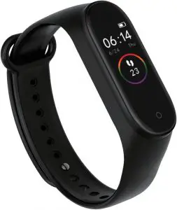
 Time: Time, date, remaining power are shown on the watch face. (Once smart band connected to the device, time will be synchronized with device time. The time cannot be set on the smart band).
 Status mode: Record user steps daily, walking distance, calories consumption
 Heart rate measurement: measure heart rate hourly, or measure heart rate manually. Press and hold to enter into heart rate measurement interface.
 Blood pressure measurement: measure blood pressure hourly, or measure blood pressure manually. Press and hold to enter into blood pressure measurement interface
 Blood oxygen measurement: measure blood oxygen hourly, or measure blood oxygen manually. Press and hold to enter into blood oxygen measurement interface.
 Sport mode: Press and hold on the sport mode interface to enter the sports selection page. There are five different sport modes for selection. Running indoor, running outdoor, cycling, sport walking, and exercise modes. Press and hold in the mode to start record exercise time, calories burnt. Press to pause, press and hold to return.
 Weather: The real-time weather condition will be synchronised with your device data and shown on the time display interface. The smart band needs to be connected to the APP and the device GPS function needs to turn on .
 More: Do not disturb (Press and hold to cancel or turn on vibration), music (press and hold to enter music control panel, press to switch, press and hold to confirm), timer (press and hold to enter timer, press to pause or start), find my phone (press for 5 second to enter phone finding mode→press to start→find the phone according to the ringtone and vibration→press to stop). Please make sure the phone and the smart band are connected and within operating range.
 Settings: Turn off (press and hold to turn off, press to switch), reset (press and hold to reset, press to switch), about (press and hold to check the firmware version, MAC address, press and hold to return or return after five second)
 Others: Charging alert, alarm reminder, sedentary reminder, incoming call display shake to take picture, system update, WeChat/QQ/Text message notification .
Q&A
- Can’t find bracelet and can’t connect with it?
- Please ensure the bluetooth is ON and the system of mobile phone is Android 4.4 or above and iOS 8.4 or above.
- If it still unable to connect, enter the phone settings —> Application Management—) Authorization Management—) Application Rights Management—>Find application [WearFit]—> Allow all permissions as “allowed”—> Enter the phone settings and select GPS location and turn on GPS function. —>Restart the phone->Try to connect.
- Please ensure bracelet is fully charged. Do feel free to contact us if it can t work normally with plenty power.
- The APP shows no connection after bound with bracelet, or it is connected but the power is 0%? In this case, the App is not bound with bracelet successfully, please rebind
- Can’t connect the device with APP? Pull down and refresh main interface, it will manually to synchronize the data, then it can display data in the APP. Auto—sync data will only be synchronized at first binding. Then it will automatic synchronize of data hourly. In addition, don t forget to open hourly measure—ment. Otherwise histogram has it any data.
- Pull—down and refresh APP,the data is not loaded? App settings Restore the factory settings->Click restore factory settings->Turn off the bracelet->Restart bracelet->Match with APP. Then data can be loaded out.
- The bracelet time is not synchronized after connecting with the phone? Mobile phone settings—’Application management/rights management—>Open permissions of APP—’Reconnect the bracelet—’Pull down and refresh it at main interface of the APP.
Basic parameters
| OLED screen size | 0.96″ inch |
| Bluetooth version | BT4.0 |
| Waterproof | I P67 |
| Battery type | Polymer lithium battery |
| Battery capacity | 90mAh |
| Charging time | 1.5-2 hours |
| Strap size | 255mm*20mm*2.2mm |
| Charge Method | Clip charging |
| Packing | Wristband, Charging Clip, User Manual |
Remark
- If there is a product quality problem or the use of products Is not clear, please contact our store by direct mail, we will deal with it quickly.
- The measurement results of this product are for reference only, not for any medical purpose and basis. Please follow the doctors instructions and do not rely on the measurement results for self diagnosis and treatment.
- The waterproof grade Is IP67, which can be used for daily life waterproof. But the bracelet can not be used for diving and put under water for long time. In addition, this product does not prevent hot water, because steam will affect the bracelet.
- Our company reserves the right to modify the contents of this manual without notification. Some functions are different in the various software version, which is normal.
FAQS
What kind of payment methods do you accept?
T/T(Bank transfer), L/C, Western Union, Money Gram, Paypal, Cash etc.
Can you print my brand name (logo) on these smart watches?
Yes of course, please contact with our sales, they will help you to customized your own case.
How about your smart bracelet quality?
We provide unrivaled Quality – Very rigorous testing process for Incoming Quality Control, Input Process Quality Control, and Final Quality Control for every piece. We follow at least 18 QC test procedure,and do 100% FQC to ensure your satisfaction.
How will you deliver my goods to me? How long do I need to wait before my goods arrive?
You can select shipping options possibly, such as DHL, UPS, FedEx, TNT ,EMS to enable our customers get their goods rapidly at door. We also ship by economic method such as air cargo and sea cargo, Direct line, Air Mail according to clients’ request.
3-7 days for international express, 5-7 days for air cargo, 20-40 days by sea cargo.
What’s the delivery time? (How long do you need to prepare my goods?)
1-2 days for sample orders
3-10 days for bulk order (based on different quantities).
Can I get a sample of this?
Yes! You can! You are welcome to place a sample order to check our superior quality and service!
How long is your Warranty?
Usually we offer 12 Months Warranty( details please ask by email ).
How do you charge a Rohs smart bracelet?
Plug it into any USB charger or USB port on your computer. Whilst charging, the white LED flashes and stops when fully charged. Charging takes about half an hour. The fitness band can be controlled by moving the wrist or via touch.
How do you set up a Rohs smartwatch?
Download the App
Method1 : Scan the code below to download the APP.
Method2: Please ensure the bluetooth is on,and open “Wearfitr”. Click the selection of link to bracelet,find the device name in the list and click it. Then enter the main interface. Scan QR code download.
How do you set up a smart bracelet?
1 Plug one end of the USB cable into the charger or into the USB port of a computer. 2 Plug the other end of the cable into the Micro USB port of your SmartBand. 1 From the Home screen of your Android™ device, tap , then find and tap Smart Connect. 2 Tap Devices > SmartBand.
How many different smart watch chargers are there?
There are two types of chargers you can use with your Samsung smart watch: a flat charging dock or a charging dock with pins. The type you need depends on which model watch you have, and the correct charger will come with your watch. If you don’t have a compatible Samsung wall charger, they can be purchased separately.
Can a smart watch be repaired?
If your device has a warranty, you may be able to exchange or get it repaired from the brand. Make sure you learn as much as you can about the smartwatch suppliers you order from.
Can we replace battery in smart watch?
If it’s time to replace your smartwatch battery, you’re in the right place! We stock a full range of smartwatch batteries, chosen for their high-quality components and long life. Select the make and model of your smartwatch from the list to find a suitable replacement smartwatch battery in no time at all!
What battery is used in smart watch?
Any rechargeable Lithium-Ion battery cell can be used, but the maximum charge current is 300mA limited by the charger device bq25120, so, it’s better to limit your battery cell capacity to 300mAH which is usual used in smartwatch and wearable device.
What batteries are in smart watch?
Lithium Ion (Li-ion) batteries are the newest standard in rechargeable batteries for electronic devices. You probably have one in your mobile phone, and this is the type of battery used in our new smartwatches, GPS trackers and other rechargeable devices.
Is it good to wear smart watch all the time?
If you wear a smartwatch 24 hours a day, the radiation it produces can cause headaches. Therefore, smartwatches should not use too long. It has often observed that people use smartwatches late into the night, causing sleep disturbances. Mood swings can cause problems with mood swings.
![]()
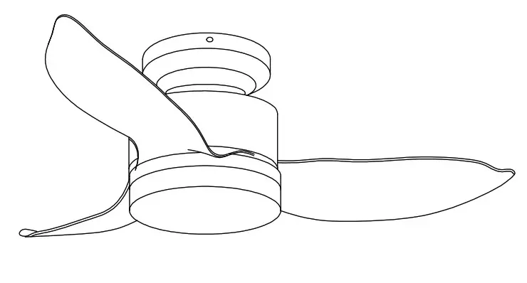
CEILING FAN INSTRUCTION MANUAL

Safety Instructions
- In order to reduce the occurrence of electric shock, the supply line is connected between the fan and must be installed an all-pole Disconnect switch, (switch contacts opening distance requirements played a 3mm). If you lack electrical knowledge, bo sure Please hold “electrician card” professional install it for you.
- To avoid electrical shock hazard, ceiling fan installation, removal before you turn off the power first, will be installed Shall be ground, FireWire, zero line order of installation, disassembly must be disassembled to the zero lines, the line of fire, earth order.
- In order to reduce electric shock or from accidents. do not use non-local governor or switch product requirements
- When a ceiling fan installation, you must determine the various parts of screws securely latched.
- Rotating ceiling fan, the blades should not touch any object to avoid danger.
- Select the appropriate location to install a ceiling fan, ceiling fan blade away from the ground should Above 2.3 meters or more Prevent accidental blade collision accidents.
- To change the fan rotation direction. please turn off and wait for the blades to stop turning after the adjustment reversing switch.
- The power of this machine is 120V/60Hz, maximum motor power of 60W (specifications of different models of ceiling fans, which Motor power will be different), each light source lamp maximum 40w.
- About how to install a ceiling fan and connect the power, please read the fan assembly procedures carefully.
- Do not clean the ceiling fan blades and clean water or detergent directly, use a dry cloth or slightly damp cloth to wipe In addition to dust. Before cleaning the ceiling fans, the ceiling fan must be disconnected from the power switch.
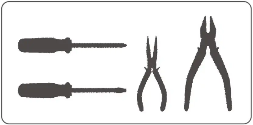
Tools Needed
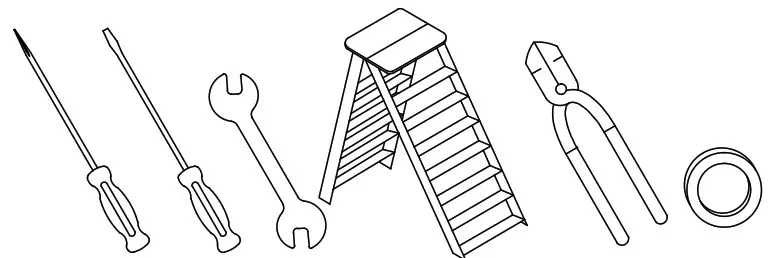
*Phillips Screwdriver
*Blade Screwdriver
*Adjustable Pliers or Wrench
*Step Ladder
*Wire Cutter
*Electrical Tape
1. Tools ready
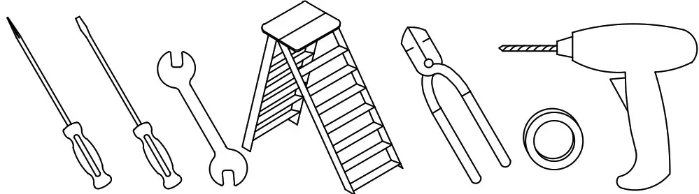
- Phillips screwdriver
- Blade screwdriver
- Adjustable pliers or wrench
- Step ladder
- Wirecutter
- Electrical tape
- Impact drill
2. Parts inspection
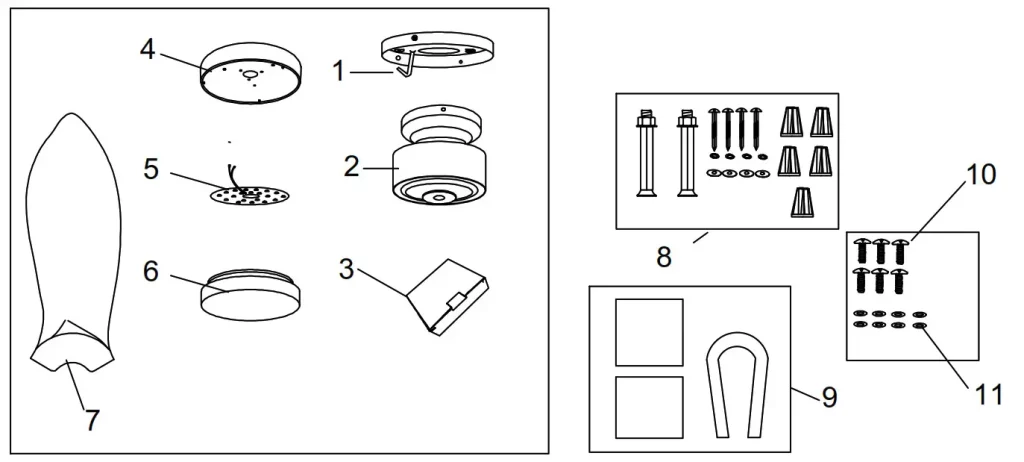
| NO. | Name | Quantity | NO. | Name | Quantity |
| 1 | Hanging board | 1 | 11 | Shim | 6 |
| 2 | Motor body | 1 | |||
| 3 | Remote control | 1 | |||
| 4 | Inner lamp holder | 1 | |||
| 5 | Led light | 1 | |||
| 6 | Lamp cover | 1 | |||
| 7 | Blades | 3 | |||
| 8 | Expansion screws | 1 | |||
| 9 | Balance package | 1 | |||
| 10 | Blade screw | 6 |
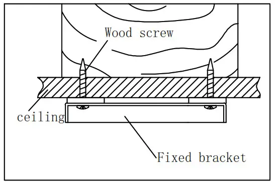
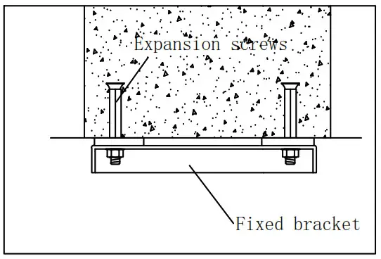
3. Install the hanger
1) Wooden ceiling wood with a wood screwdriver in the wood or “Aberdeen” will be fixed on the lifting tight.
2) In the concrete ceiling, first with a length of the expansion screw, and then use expansion screws with the hanger bracket fixed to the ceiling.
4. Install the lamps
1) The other two blades are also fixed on the blade frame.
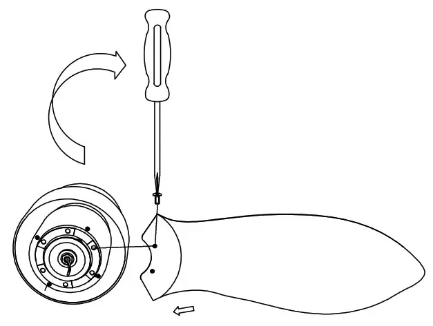
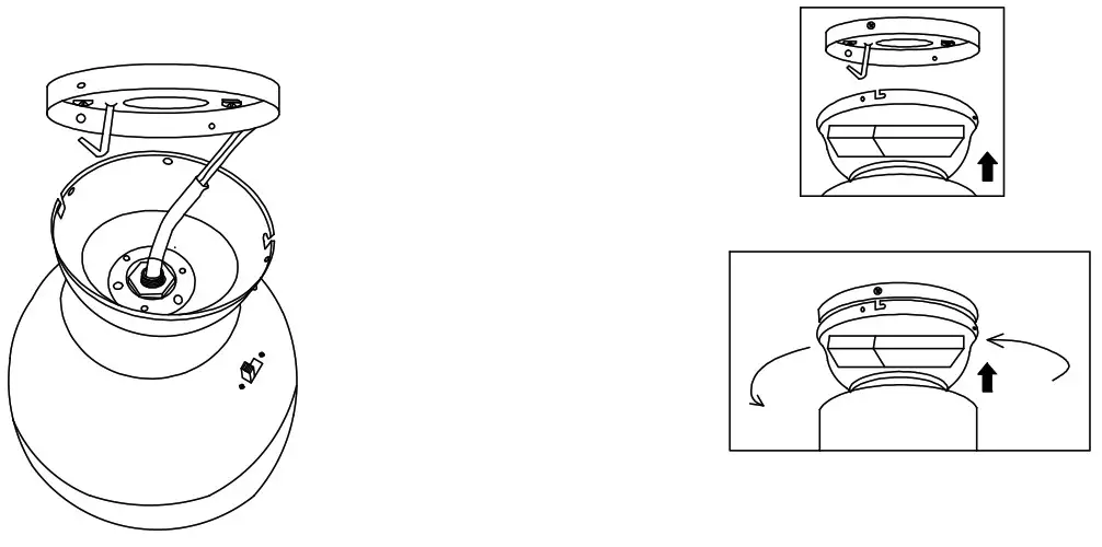
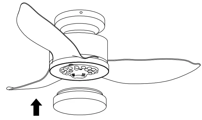
5. Fixed ceiling fan
1) Hang the installed main engine on the pre-locked hanging plate (note. The hook of the hanging disc passes through an oval hole on the bell from the inside to the outside, and then connect the wires of the remote controller according to the wiring mode, take off the main machine, let the L-shaped symmetry of the belt clip into the reserved screws, turn the main body to make the screw holes on the other side right, and then lock the four screws with a screwdriver.
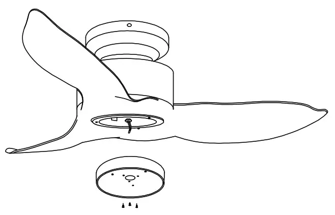
6. Install the lamp panel light source
1) First remove the screws on the junction box of the host machine, and then align the hole position of the lamp panel with the hole position of the screws removed from the junction box, and lock it with screws.
2) Connect the lead of LED light source and the light wire of the host with terminals.
3) Then attach the light source to the lamp panel
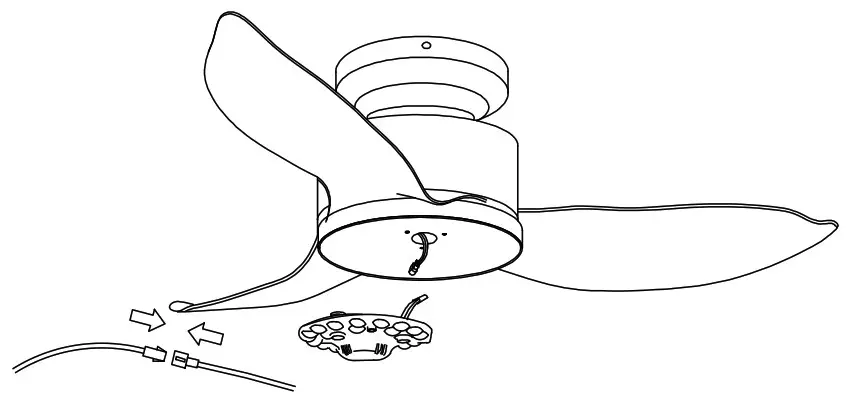
4) Turn the glass lampshade into the lamp panel and install the lamp.
7. Installation height
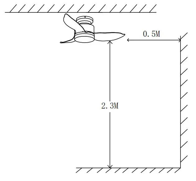
The height of fan leaves from the ground shall not be less than 2.3m Not less than 0.5m away from the wall
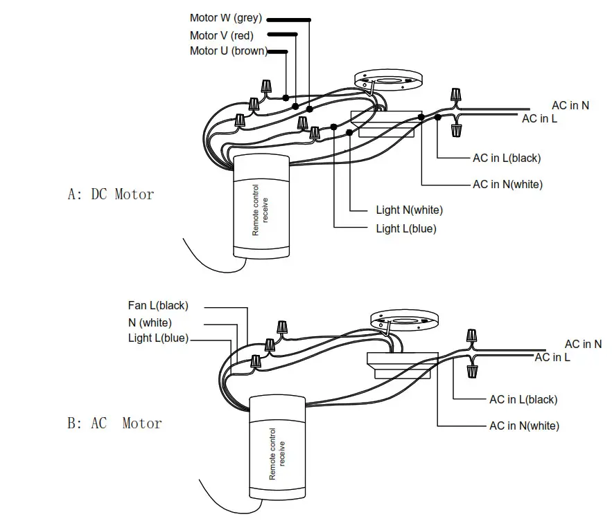
8. Connect the power cord
9. The balance adjustment of the fan Fan is installed, if it shakes up and down, please check the screws in blades, download, and the lamp kit if they are fixed, if not, please fix it with a screwdriver. If it still shakes, please use the balancing kit stools and check the instruction of the balancing kit inside the carton.
Warm Tips: the Maintenance of Ceiling Fans
- Because the ceiling fan always runs, please check regularly whether the hanger, fan blade, leaf rack, and other parts are loose, if not, please fasten it in time to ensure it run safely.
- Keep ceiling fans clean regularly. Only use a soft brush or a lint-free cloth to clean it gently. Do not use a damp cloth or another destructive cleaner.
- Don’t add lubricating oil or lubricant to any part of this product.
Wireless Earbuds T3
V4
Operating Manual
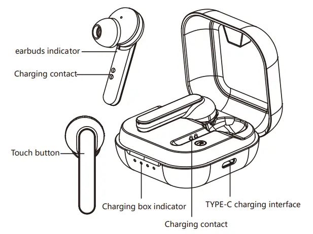
Product Overview
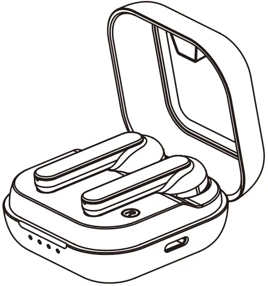
Packing list:
A. TWS Bluetooth earbuds 1 pair (1 charging case)
B. earbud caps (large, medium, small) 1 set each
C. Type-C charging cable 1 piece
D. Operation instructions 1 copy
Basic Features
| Button | Function | Operation method |
| Touch button |
On | Users may turn on the earbuds after opening the charging case
• When there is a pairing record, the earbuds will be re-connected to the device to which it is connected last time after being picked up from the charging case and turned on. If the reconnection fails, it will enter the Bluetooth pairing mode |
| Off | In the “On” state, the user may turn off the earbuds after putting them into the charging case and closing the cover | |
| Play/Pause | Users can play/pause music after turning on the music player and clicking the touch button on the left or right ear | |
| Previous | In the process of playing music, the user may switch to the previous track after double-clicking the “touch button” on the left ear | |
| Next | In the process of playing music, the user may switch to the next track after double-clicking the “touch button” on the right ear | |
| Answer | In the connected mode, the user may answer the call after clicking the “touch button” (either “touch button” on the left or right ear) | |
| Hang up | During the call, the user may hang up after clicking the “touch button” (either “touch button” on the left or right ear) | |
| Reject | When there is an incoming call, double-click the “Touch key” (on either left earbud or right earbud) to reject the call | |
| Wake-on-voice | In standby or music mode, the user may start voice assistant (either “touch button” on the left or right ear) by pressing and holding the “touch button” for 2-3 seconds and release after hearing the “beep” sound. * Require mobile phone support. |
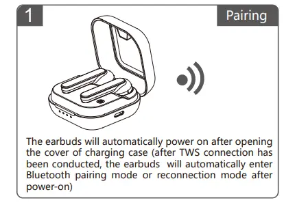
Bluetooth Pairing and Connection
A. During the first connection, the earbuds will automatically power on and pair after T3 charging case is opened, and the main ear will automatically enter the Bluetooth pairing mode in case TWS pairing is completed successfully after 5S.
B. Turn on the mobile phone and Bluetooth, search for Bluetooth devices, search for “Willful T3” and click “Willful T3” for pairing and connection; after a successful connection, the mobile phone will display that “Willful T3” has been connected. At this time, the user may listen to music or call on the mobile phone through Bluetooth earbuds.
C. User may control the functions of answering, hanging up, previous track, and next track through the touch button of Bluetooth earbuds.
Indicator
4.1. Bluetooth indicator of earbuds
| Status | Tone |
| On | The white indicator is on for 3 seconds |
| Off | No LED indicator |
| dual-pairing mode? | The white indicator is flashing quickly |
| Bluetooth pairing state | Main earbud: white indicator flashes once every 3 seconds |
| Auxiliary earbud: white indicator flashes once every 10 seconds | |
| Clear pairing record | The white indicator is on for 2 seconds |
| Connected and standby state | Main record: white indicator flashes once every 10 seconds |
| Auxiliary record: white indicator flashes once every 10 seconds | |
| Charging | No indicator on earbuds (the indicator of the charging case is on according to the dump energy) |
| Low battery alarm | The white indicator flashes once every 2 seconds |
4.2. dump energy indicator of charging case
| Status | Indicator |
| When the residual power is 0% – 25% | The first white indicator is on |
| When the residual power is 25% – 50% | The first and second white indicators are on |
| When the residual power is 50% – 75% | The first, second, and third white indicators are on |
| When the residual power is 75% – 100% | The four white indicators are on |
4.3. Charging indicator of charging case
| Status | Indicator |
| Charging with the power of 0%- 25% |
The first while indicator is slowly flashing |
| Charging with the power of 25% – 50% |
The first white is on and the second white indicator is slowly flashing |
| Charging with the power of 50% – 75% |
The first white indicator is on, the second white indicator is on, and the third white |
| Charging with the power of 75% – 99% |
the indicator is slowly flashing The first white indicator is on, the second |
| Fully charged | and third white indicators are on and the fourth white indicator is slowly flashing The four white indicators are on |
TTS English Prompt Tone
| Prompt tone | Power on | Power off | Pairing | connected | Disconnected | Battery Low |
Charging
In the case of the T3 low-power alarm, please immediately put the earbuds into the charging case to charge. The charging time is 2 hours. When the earbuds are being charged, the indicator of the charging case will display the current power of the charging case. When the earbuds is fully charged, the indicator of the charging case will go out.
Charging connection
Please connect the Type-C joint of the charging cable to the Type-C charging interface of the charging case and the USB joint to the USB charger (car charger, travel charger, computer USB, etc.).
Product Specifications
| Bluetooth specifications | Bluetooth 5.0 |
| Frequency range | 2.402-2.480GHz |
| Supporting protocol | I-IFP, HSP, AVRCP, A2DP |
| Chip Solution | AB1536U |
| Decoding method | SBC MC |
| Range of application | Up to 10 meters |
| Battery capacity | Earbuds: 3.7V 40mAh / Charging case: 3.7V 420mAh |
| Net weight | 46.6g (earbuds: 4.3g ” 2; charging case: 38g) |
| Dimensions | Earbuds: 17.1 ” 23.8 ” 43.1 mm Charging case: 53.5 ” 53.5 ” 28mm |
Notes and Q & A
A. How to connect? What should I do if re-connection fails? What should I do if only one earbud is working normally? After T3 is successfully connected to your mobile phone, it will automatically connect to your mobile phone every time you turn it on. If re-connection failed or only one earbud is working normally, you need to put the earbuds in the charging case, close its cover and keep for 5S, and then open the charging case for connection.
B. How to clear the pairing record?
After the earbuds is turned on, you may press the touch key for
three times to clear the pairing history. After the pairing history is
successfully cleared, the earbuds indicator will be on for 2S and
then enter the left and right ear pairing state again.(This function can only be used when the earbuds work abnormally that only a single earbud can be connected with. You need to disconnect the device when clearing the pairing. )
C. What devices can I use to charge?
All car chargers travel chargers, and computer USBs with a DC voltage of 5V and current of 1A can be used to charge.
NOTE: This equipment has been tested and found to comply with the limits for a Class B digital device, pursuant to part 15 of the FCC Rules. These limits are designed to provide reasonable protection against harmful interference in a residential installation. This equipment generates uses and can radiate radio frequency energy and, if not installed and used in accordance with the instructions, may cause harmful interference to radio
communications. However, there is no guarantee that interference will not occur in a particular installation. If this equipment does cause harmful interference to radio or television reception, which can be determined by turning the equipment off and on, the user is encouraged to try to correct the interference by one or more of the following measures:
– Reorient or relocate the receiving antenna.
– Increase the separation between the equipment and receiver.
-Connect the equipment into an outlet on a circuit different from that to which the receiver is connected.
-Consult the dealer or an experienced radio/TV technician for help
Changes or modifications not expressly approved by the party responsible for compliance could void the user’s authority to operate the equipment.
This device complies with Part 15 of the FCC Rules. Operation is subject to the following two conditions:
(1) this device may not cause harmful interference, and (2) this device must accept any interference received, including interference that may cause undesired operation.
FCC ID: WSG-T3

Made in china
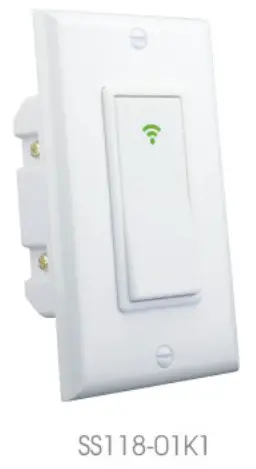
]]>User Manual
Power Supply: AC 100~240V
Rated Frequency: 50/60HZ
Max. Current: 10A/240V/gang
Max. Power: 800W/gang
Wifi: IEEE 802.11 b/g/n
Wireless Standard: WiFi 2.4GHz
App Support: iOS/Android
 Input voltage: AC 100-240V
Maximum current: 10A/ 240V/gang
Transmission power: <2 mw;
Load power: <800W
Since the power consumption: <0.5W
Detection Angle: 180°
Detection range: 3-5 m.
Delay time: 30 seconds
Light induction degree: 8 + 3 LUX
Small night light power: 2W Warm color light
Wifi: IEEE 802.11 b/g/n
Tools You Will Need
IMPORTANT
The fixture controlled by the wifi in-wall smart switch must not exceed 960 watts (incandescent); 800w (10A) Resistive or hp motor. The switch is designed only for use with permanently installed fixtures.
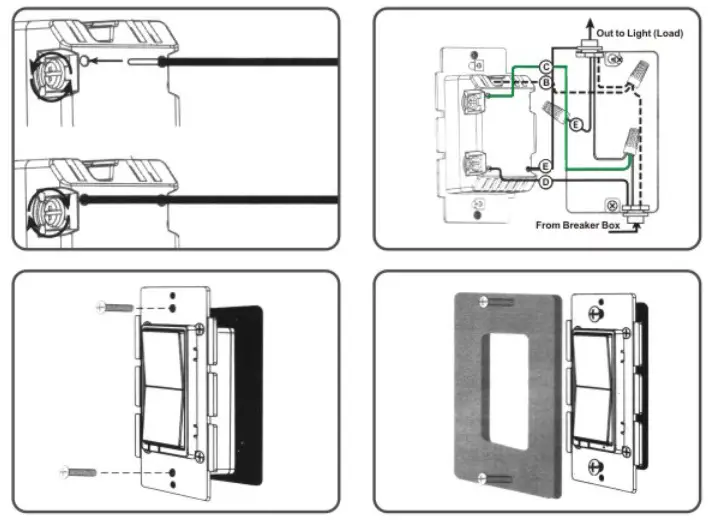
Switch key and wiring position description.
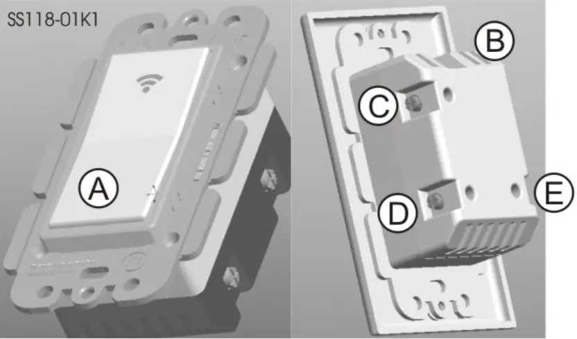
A. Switch button
- Press/release to tum the switch on/off
- Reset the light switch: Press any key of the device for 20
seconds till light flashes, which indicates a successful reset
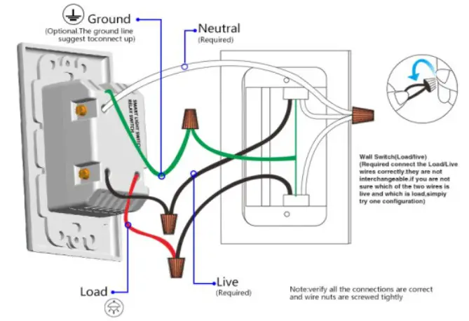
B. Ground wire (green/bare)
C. Neutral wire (white)
D. Live wire (black)
E. Load wire (black)
- US Smart switch indicator description
1. When the wifi signal is in red, it means the switch is on.
2. When the wifi signal is in the blue light, it means the switch is in the off standby state.
3. When the wifi signal light is flashing green, the switch is in the state of fast distribution. Follow the instructions.
4. When the wifi signal light is flashing green slowly, the switch is in the AP distribution network state, and the operation is prompted according to the instructions;
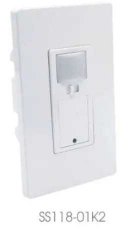
5. When the wifi signal light is steady green, the switch cannot connect to the network. Please check the router network. - Night light sensor smart switch button description
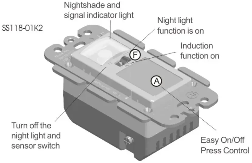 Function button description:
1. Astands for the button switch, press/release to turn the switch on/off
1.1 Rest the light switch :press any key of the device for 20 seconds till light flashes, which indicates a successful reset
2. F stands for the function switch,
2.1 When the F toggle switch is OFF, turn off the sensor switch function and the night light function, and retain the function of the smart button switch.
2.2 When the F toggle switch is in Auto, turn on the sensor switch function, turn off the night light function, and retain the smart button switch function;
(1) When the F toggle switch is in Auto, the light is automatically turned on when the human body passes near the switch about 3 meters, no manual switch is required.
(2) When the F toggle switch is in Auto, the light is automatically turned off when no human movement is detected for 30 seconds.
(3) When the switch is in a bright environment, the luminaire is automatically turned off and the auto-sensing function is turned off.
3. When the F toggle switch is in the LED, turn off the sensor switch function, turn on the night light function, and keep the smart button switch function.
(1) When the F toggle switch is in the LED, the night light will automatically turn on when the room light is dark.
(2) When the F toggle switch is in the LED, the night light will automatically turn off when the room light is bright.
4.Description of the night light sensor Smart switch indicator. See the same above (2.1)
Note:
1. When the switch senses light, the sensing function is automatically turned off.
2. Switch is in standby state, blue light is not bright.
Calculate the actual horizontal detection distance method
Note: The horizontal installation is up to 180°, designed to prevent the detection switch from detecting the space above the ceiling.
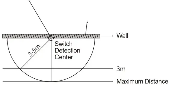
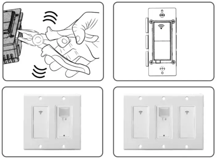
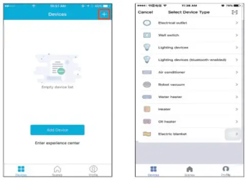
- The side angle of the sheet metal can be disassembled, Can be combined 2gang, 3gang.
Switch wiring installation
Warning-shock hazard
Turn off the power to the branch circuit for the switch and lighting fixture at the service panel. All wiring connections must be made after power down to avoid personal injury and / or damage to the switch. This device is intended for installation in accordance with the national electric code and local regulations in the United States, or Canadian electrical code and local regulations in Canada. If you are unsure or uncomfortable about performing this installation, consult a qualified electrician.
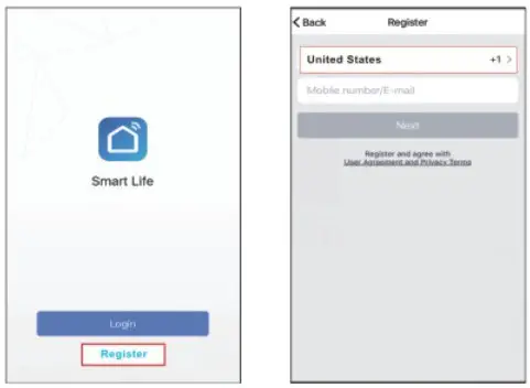
Multi-switch wiring
For 3-way installation, please refer to add-on manual single switch wiring before you start: you may wish to change the paddle color to match your wall plate or decore. please proceed to section 5.
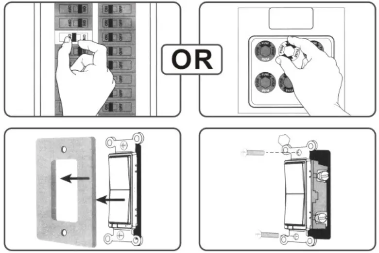
- Shut off the circuit power at circuit breaker or fuse box (IMPORTANT!!! Make sure the power is OFF to switch box before continuing.)
- Remove wall plate
- Remove the switch mounting screws
- Carefully remove the switch from the switch box.
DO NOT disconnect the wires. - There are up to five screw terminals on the switch.
These are marked
A. Switch button
- Press/release to tum the switch on/off
- Reset the light switch : Press any key of the device for 20 seconds till light flashes which indicates a successful reset
B. Ground wire (green/bare)
C. Neutral wire (white)
D. Live wire (black)
E. Load wire (black)
Installation Instruction
Easy to install,better to operate by a licensed electrician
 Simplified steps to install the App on your smart device and pair with Amazon Alexa, Google Assistant and IFTTT using Smart Life App on Apple Store/Google Play Store. Compatible with any smart phone or tablet including both Android and iOS systems.
- Download Smart Life from iOS APP Store or
 .
.
Download or scan the QR code and install the Smart Life App for either iOS or Android.
Once downloaded, the app will ask you to register your device. Enter your phone number or email which ever one makes you feel comfortable and select the country you live in. If phone number selected you will receive a text with If you choose email you will needed if email method then create a password. 6 chosen.

Attention: There’s no a registration code. Registration code
 Attention: there’re two modes for configurabions(Quick Mode/AP Mode) available for you to choose before adding the device to your App. Quick Mode is recommended.
Quick Mode Configuration (Common)
- Make sure quick mode configuration is initiated: the indicator light blinks blue rapidly (twice per second). If it blinks blue slowly (once every 3
seconds), press and hold the power button on your Smart Switch for 20 seconds until the indicator light blinks rapidly. - Tap the icon “+” on the top right corner of choose your device type and enter “Add Device”
- Follow the in-app instructions to connect the Smart Switch to your Wi-Fi network.
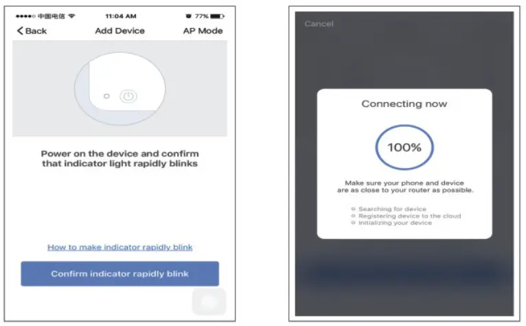
- Once connected, the App will prompt the connection, and click “Done”.
- Now you can control the smart switch through Smart Life App.
- Once the configuration is completed successfully, the indicator light will turn to solid red and the device will be added to the “Device List”.
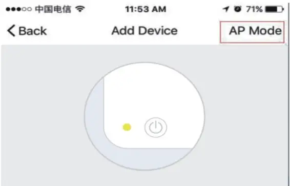
AP Mode Configuration
- Make sure AP mode configuration is initiated: the indicator light blinks blue slowly (once every 3 seconds). If it blinks blue rapidly (twice per second), press and hold the power button on you Smart Switch for 20 seconds until the indicator light blinks slowly.
- Tap the icon “+” at the top right corner of “Start your smart life” tab and then click “AP Mode’ at the top right corner of “Add Device” tab to add device.
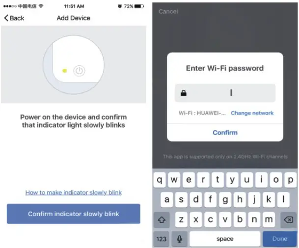
 Power on the device and confirm that indicator light slowly blinks How to make indicator slowly blink Confirm indicator slowly blink
Indicator light is in other status - Follow the in-app instructions to connect the Smart Switch to your Wi-Fi network.
- Once connected, the App will prompt the connection, and click “Done”.
- Now you can control your Smart Switch through Smart Life APP.
- Once the configuration is completed successfully, the indicator light will turn to solid red and the device will be added to the “Device List”.
Please note: you can add the Smart Switch to Echo/Google Home following this instructions below, or one on the App (Open Smart Life App, go to “Profile” – > “Integration” ,tap”Amazon Echo”or”Google Home’and install).
How to connect your Smart Switch to Amazon Alexa
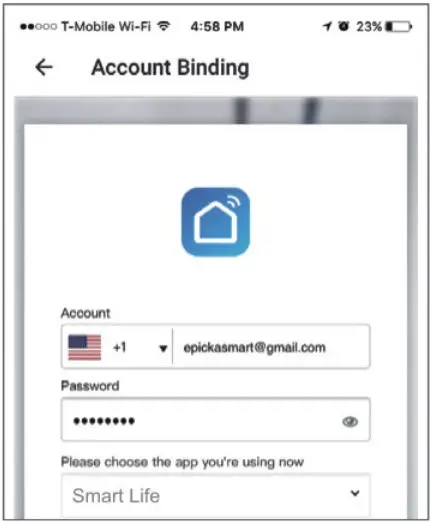
- Launch Smart Life App, sign in your account and make sure your Smart Switch is in your device list.
- Name each device, such as living room light or bedroom light, so that Alexa can easily recognize them.
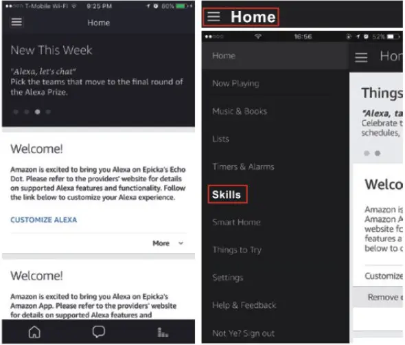
- Minimize Smart Life App, then launch the Alexa App and sign in your Alexa account and make sure you have at least one Alexa voice-controlled device installed like Echo, Echo dot, etc.
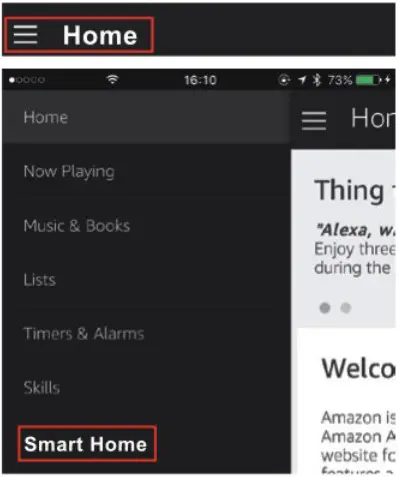
- In the upper left corner of Home page, click
 button to show App menu. Then clicks
  in the menu.
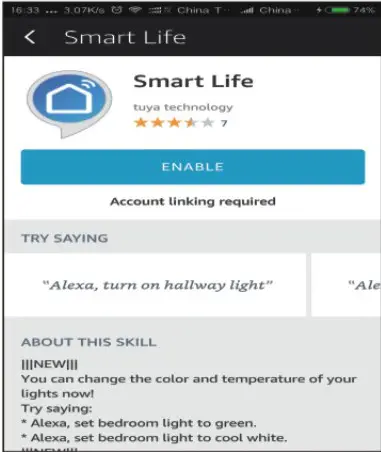
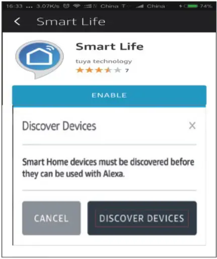
- Type in “Smart Life” in the search and click the search button.

- Enable Smart Life, then sign in your Smart Life account to complete the account linking.
- After successful account linking, ask Alexa to discover devices. After a 20-second device discovery, Alexa will show all the discovered devices.
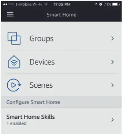
- Back to Menu by clicking
 button, and then click
  button.
- In Smart Home page, you can group your devices for different categories. Your Smart Life APP has been skilled with Alexa. Now you can control your Smart Switch via Alexa.
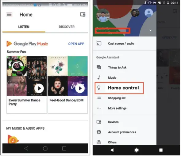
How to connect you Smart Switch to Google Home
- Launch the Google Home App and make sure Google Home speaker is installed. If not,please follow the Google Home Speaker installation to install it first.
- Once Google Home is installed, in the upper left corner of App Home page, click
 button to show App menu. Then clicks “Home Control” in the menu.
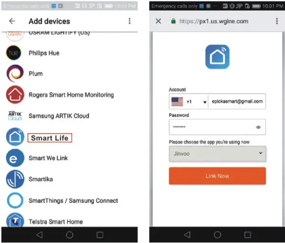
- On “Add devices” page, scroll down to find “Smart Life” and then click it. Sign in Smart Life App with your Smart Life App account and password choose Smart Life App in the dropdown menu to complete the account linking.
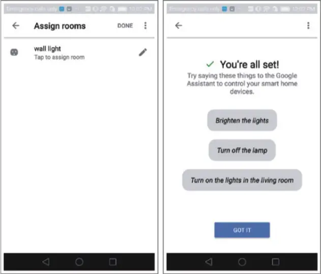
- After successful account linking, in Google Home App you can see all the smart devices from your Smart Life App account. You can assign rooms for each device.
- Now you can use Google Home to control your smart devices, you can Say like:
Ok Google, turn on/off wall light
Ok Google, set bedroom light to red
 5.1 Command the Device through Your Voice
After complete the above operations, you can control the device via Google Home.
Firstly, you need to say “Ok Google, talk to Smart Life” to wake up theSmart Life. Then you can control devices by instructions like these:
 Turn on Smart Switch
Turn off Smart Switch
Attention: after Smart Life has been waken up. you can say “Cancel” or “Stop” to exit Smart Life or say “nothing” when you hear “What can | do for you”. Then says again “Ok Google, tale to Smart Life’to start voice control.
IF TTT – Setup and Usage
Get Started: How to connect Smart product to IFTTT?
Step 1.
Visit the IF TTT official website on your PC and sign in with your IFTTT account.
Note: You can also use IFTTT app and follow similar steps to connect your device to the IFTTT. In this FAO we take the website setting methed for example.
Step 2.
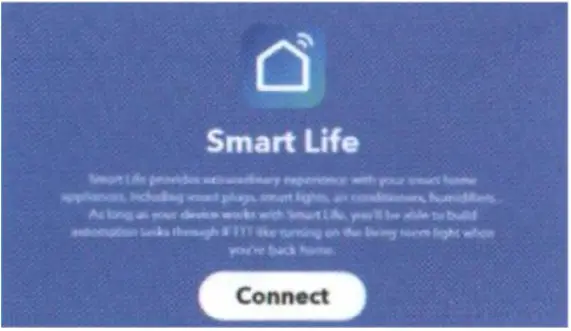
“Search” for “Smart Life’, and then click “Smart Life” service.
Step 3.
Click “Connect”, then login your Smart Life ID and then tap
“Link Now”.
 Step 4.
Successfully connect your IFTTT account to your Smart Life ID. You are ready to enjoy the IFTTT service of products now.
Instructions: 2 methods to use IFTTT with Smart products.
Method 1: On Smart Life swrvice page. choose an existing Applet you need, turn on it and then finish the configuration.
Method 2: Create a new Applet on your own.
Click “My Applets” at the top and then click “New Applet” at theright top corner of the webpage to create a new Applet.
Step 1. Create a Trigger.
Tap “this” to choose a Trigger, You can search for “Weather Underground” to choose a Trigger.
We select “Sunset” Q weather as the Trigger.
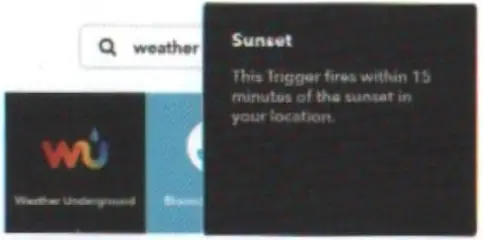 Step 2. Create an Action.
Tap “this” to choose a Action, You can search for”smart life” to choose a Smart Life Action.
We select “Turn on”
Light Switch as the Action in this case. 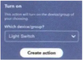 Step 3.
New Applet “If sunset, then turn on Light Switch” is created as a resuit.
Note: The Smart Life service can only works when create an action. You can’t use the “Smart Life” as a Trigger.
Troubleshooting and FAQ
- What devices can I control with the Smart Switch?
You can control lights, in accordance with the Smart Switch specifications. - What should I do when I cannot turn Smart Switch on or off ?
• Make sure your mobile devices and the Smart Switch are connected to the same Wi-Fi network.
• Make sure the devices connected to the Smart Switch are turned on. - What should I do when device configuration process has failed?
You could:
• Check whether the Smart Switch is powered on or not.
• Check whether your mobile device is connected to
2.4GHz Wi-Fi network.
• Check your network connectivity. Make sure the router is working properly:
* If the router is dual-band router, select 2.4G network and then add Smart Switch.
* Enable the router’s broadcasting function.
* Configure the encryption method as WPA2-PSK and authorization type as AES, or set both as auto.
* Wireless mode cannot be 11n only.
* Check for Wi-Fi interference or relocate the Smart Switch to another location within the signal range.
* Check whether the router’s connected devices reach the amount limit. Please try to turn off some devices’ Wi-Fi function and configure Smart Switch again.
* Check if router’s wireless MAC filtering function is enabled. Remove the device from filter list and make sure the router is not prohibiting Mini Smart Switch from connection.• Make sure the password of your Wi-Fi network entered in App is correct when adding Smart Switch.
• Make sure the Smart Switch is ready for App-Config: the indicator light is quickly blinking blue (twice per second) for Quick mode configuration, slow blinking blue (once every 3 seconds) for AP mode configuration.
• Repeat the App-Config process.
• Factory reset the Smart Switch and try to add it again.Sensing function common problems and solutionsMalfunction The reason Solution Proximity sensor light is not bright 1.Light sense control chip is on
2.Bad bulb
3.Dial power is off1.Keep the device in the dark
2.Change bulb
3.Dial the power supply to the AUTO positionInduction lamp does not go out Continuous sensing signal in the detection area Stop moving in front of the switch Induction light is on when there is no signal There is a positional movement signal (moving behind the wall, moving small objects. etc.) Check the surrounding environment There is a moving signal but the sensor light is not lit The detection area is too mall or the light sensitivity is weak Check the detection area and photosensitivity environment
Model: K3 Pro
Introduction
Specification
- Accuracy: ±0.2 degrees(35~42℃,place it in the operating environment for 30 minutes before use)
- Alarm Function: abnormal automatic alarm, flash + sound alarm for about 10 seconds
- Measuring distance: 5cm~10cm automatic measurement
- Display: LCD display
- Transmission interface: USB Type C
- Adaptable power supply: 4 AA batteries (external power supply and internal power supply can be switched)
- Install method: nail hook, bracket fixing
- Environment temperature: 10℃~40℃ (recommended 15℃~35℃)
- Measuring range: 0~50℃
- Response time: 0.5s
- Standby: 30s automatic standby during non-working hours
- Input: DC 5V 500mA
- Weight:303g
- Dimensions: 170X115X140mm
- Counting capacity: 9999 times
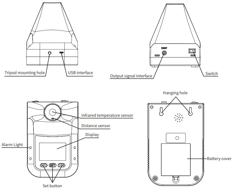
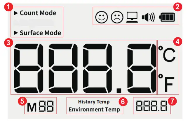
Display Description
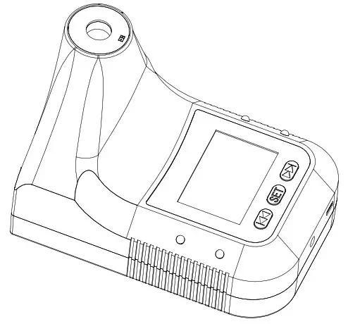
- Working mode: count mode, working mode, surface mode.
- Status indication: expression, USB connection status, volume, power.
- Measurement result: temperature status or count status.
- Temperature unit: Celsius or Fahrenheit.
- Setting item or historical record: M** indicates the historical record number* indicates the setting item number.
- History Temp or Environment Temp.
- Environment temperature status.
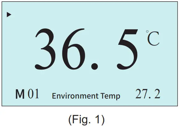
State description
- Standby:
The backlight is turned off and the temperature remains displayed. (Fig. 1)
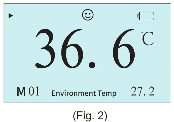
- Insufficient power:
The display indicates that the battery is empty and the icon flashes.(Fig. 2)
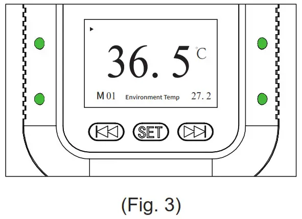
- Normal temperature:
Flashing green lights on both sides
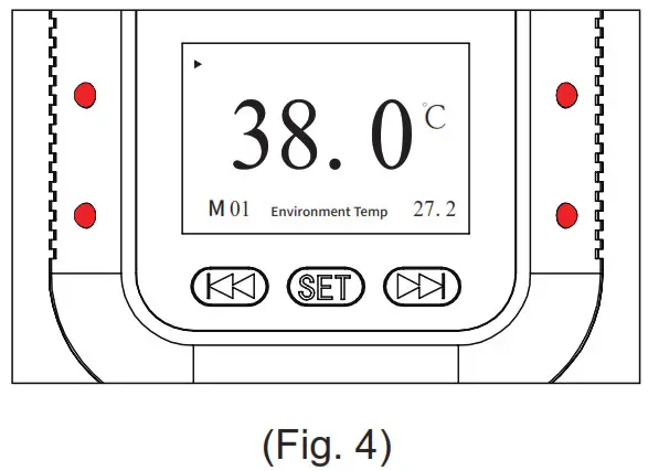
- Abnormal temperature:
Flashing red lights on both sides
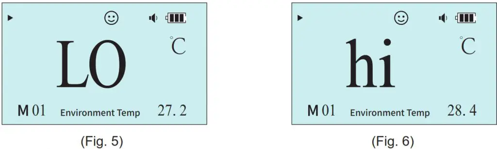
- Out of range(in working mode)
‘Lo’: Ultra-low temperature than 35 degrees Celsius(Fig. 5)
‘HI’: Ultra-high temperature than 42 degrees Celsius(Fig. 6)
Operation Instruction
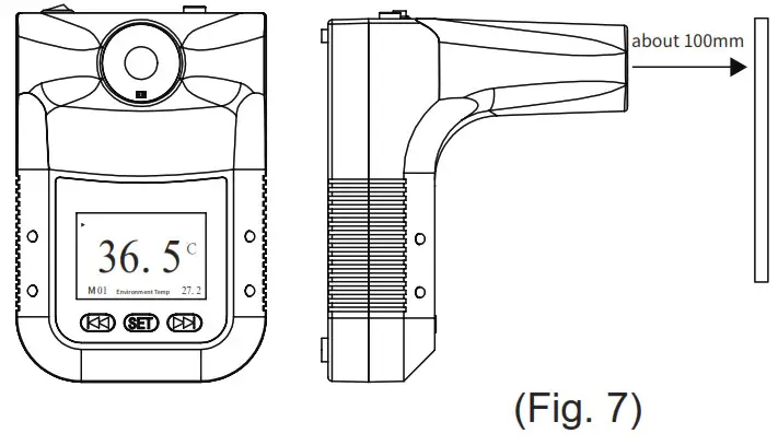
- Temperature measurement:
Front of the thermometer, approach it within 5-10cm.(Fig. 7)
- History temperature query:
Press the left and right buttons to query the historical temperature, M** represents the current historical temperature.The device currently supports up to 30 historical temperatures.
- Temperature unit setting:
Press the SET button to F1, press the left and right buttons to switch between Celsius and Fahrenheit. C:Celsius F:Fahrenheit
- Mode setting:
Press the SET button to F2, press the left and right buttons to switch the working mode.
- Alarm temperature setting:
Press the SET button to F3, it is the alarm setting state of the working model. Press the left and right buttons to switch the alarm
temperature between 37.0~38.0. The default is 37.3 ℃.
Note: The alarm temperature is only valid in the working mode.

- Volume setting:
Press the SET button to F4, it is the volume setting state. Press the left and right buttons to adjust the volume. The more parentheses
behind the small speaker, the greater the volume, and the disappearance of the small speaker represents mute.
- Backlight setting:
Press the SET button to F5, it is the backlight setting state. Press the left and right buttons to turn the backlight on or off.
ON: turn on the backlight
OFF: turn off the backlight
- Language setting:
Press the SET button to F6, press the left and right buttons to switch the language of the voice broadcast.
CH: Chinese EN: English

- Output signal setting:
Press the SET button to F7, press the left and right buttons to switch the output signal type. S1 represents the switch mode and S2 represents the pulse mode.
For more instructions about output signals.
please refer to the output signal user guide.

- Battery installation:
Open the battery cover and install the new battery correctly according to the battery polarity.

- Install method: nail hook, bracket fixing

Warnings
- It is the user’s responsibility to ensure the electromagnetic compatibility environment of the device so that the device can work normally.
- It is recommended to evaluate the electromagnetic environment before using the device.
- When changing the operating environment, the device must be left to stand for more than 30 minutes.
- Please measure the forehead to the thermometer.
- Please avoid direct sunlight when using outdoors.
- Keep away from air conditioners, fans, etc.
- Please use qualified, safety-certified batteries, unqualified batteries, or non-rechargeable batteries used may cause fire or explosion.

USER MANUAL
VS162 / VS164
Package Contents
The VS162 / VS164 Video Splitter package contains the following items:
- 1 VS162 / VS164 Video Splitter
- 1 Power Adapter
- 1 User Instructions*
Check to make sure that all the components are present and that nothing got damaged in shipping. If you encounter a problem, contact your dealer.
Read this manual thoroughly and follow the installation and operation procedures carefully to prevent any damage to the unit, and/or any of the devices connected to it.
* Features may have been added to the VS162 / VS164 since this manual was printed. Please visit our website to download the most up-to-date version of the manual.
Overview
The 2-port VS162 and 4-port VS164 video splitters chart a new direction in multimedia functionality by combining DVI quality video and audio. They take the signals from an audio/video source and replicate them to two (VS162) or four (VS164) audio/ video outputs.
Splitters can be cascaded to three levels to handle up to 64 monitors (VS164), which makes them the ideal solution for situations such as:
a) Broadcasting video information to the public (news headlines, stock prices, airline, and train schedules, etc.)
b) Company training facilities
c) Classroom instruction
Features
- Connects computers with DVI graphics to multiple DVI compatible monitors or projectors
- Fully compliant with the DVI-digital and DVI-analog
- Supports DDWG (Digital Display Working Group) standard for DVI compliant monitors
- Speaker enabled for audio enjoyment
- Cascadable to 3 levels – provides up to 8/64 video signals
- Cascade distance: Source to Device – 1.8m, Device to Device – 5m, Device to Display – 5m
- Installs in minutes
- Maintains the highest single link video resolution (up to 1920 x 1200)
- DDC, DDC2, DDC2B Compatible (Port 1 only)
- DDC/CI support – allows color, brightness, contrast and other adjustments to be made via GUI for DDC/CI-enabled LCD monitors
- HDCP compliant
System Requirements
Consoles
- A DVI display that matches the computer’s DVI display card that is capable of the highest resolution that you will be using on the DVI output.
- Speakers for audio output (optional)
Computers
The following equipment must be installed on any computer that acts as a source of DVI content:
- A DVI-I or DVI-A display port
Note: The quality of the display is affected by the quality of the DVI display card. For best results, we recommend you purchase a high-quality product.
- Audio out port (optional – for audio accompaniment to the display)
Cables
Two (VS162) or four (VS164) sets of DVI cable are required to properly operate this DVI Switch (not included).
Note:
- Cables are not included in this package. Since the quality of the display is affected by the quality and the length of the cables, we strongly recommend that you purchase high-quality cables. Contact your dealer to purchase the correct cable sets for your switch.
- There are three types of DVI signals (DVI-I, DVI-A, DVI-D).
The cable-type must match the type of signal being used by the DVI source and the DVI display.
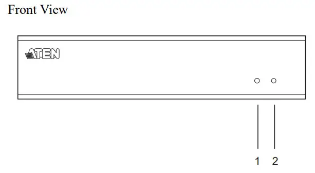
Components

| No. | Component | Description |
| 1 | Activity LED | Lights to indicate that there is a working DVI connection to the computer. |
| 2 | Power LED | Lights to indicate that the VS162 / VS164 is receiving power and is up and running. |
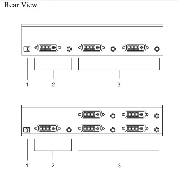
| No. | Component | Description |
| 1 | Power Jack | The power adapter cable plugs in here. |
| 2 | A/V Input Section | The cables from your source device’s DVI video and speaker ports plugin here. |
| 3 | A/V Output Section | The cables from your DVI monitors and speakers plugin here. |
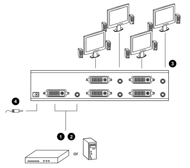
Installation
- Make sure that the power to any device that you connect to the installation has been turned off. You must unplug the power cords of any computers that have the Keyboard Power On function.
- Make sure that all devices you will be installing are properly grounded.
Single Stage
Refer to the installation diagram on the next page (the numbers in the diagram correspond to the numbers of the steps) and do the following:
- Use a male-to-male DVI cable to connect your source device’s DVI port to the VS162 / VS164’s Video In port.
- Use a male-to-male audio cable to connect your source device’s speaker port to the VS162 / VS164’s Audio In port.
- Plug your DVI monitors and speakers into the A/V Outports.
- Plug the power adapter that came with your switch into an AC power source, then plug the power adapter cable into the switch’s Power Jack.
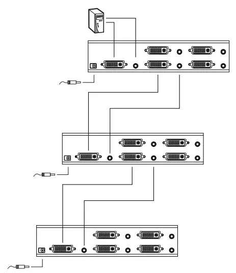
Cascading
To provide even more audio/video display, additional units can be cascaded from the VS162 / VS164’s A/V Outports. Simply use additional male-to-male DVI and audio cables to connect an A/V Out port on the parent splitter to the A/V In the port of the child splitter.
Recommended distances between devices in all cascade levels for transmitting a high-resolution signal are as follows:
Source to VS162 / VS164: 1.8 m
VS162 / VS164 to VS162 / VS164: 5 m
VS162 / VS164 to display: 5 m
- This product is for indoor use only.
- Read all of these instructions. Save them for future reference.
- Follow all warnings and instructions marked on the device.
- Do not place the device on an unstable surface (cart, stand, table, etc.). If the device falls, serious damage will result.
- Do not use the device near water.
- Do not place the device near, or over, radiators or heat registers.
- The device cabinet is provided with slots and openings to allow for adequate ventilation. To ensure reliable operation, and to protect against overheating, these openings must never be blocked or covered.
- The device should never be placed on a soft surface (bed, sofa, rug, etc.) as this will block its ventilation openings. Likewise, the device should not be placed in a built-in enclosure unless adequate ventilation has been provided.
- Never spill liquid of any kind on the device.
- Unplug the device from the wall outlet before cleaning. Do not use liquid or aerosol cleaners. Use a damp cloth for cleaning.
- The device should be operated from the type of power source indicated on the marking label. If you are not sure of the type of power available, consult your dealer or local power company.
- The device is designed for IT power distribution systems with 230V phase-to-phase voltage.
- To prevent damage to your installation it is important that all devices are properly grounded.
- The device is equipped with a 3-wire grounding-type plug.
- This is a safety feature. If you are unable to insert the plug into the outlet, contact your electrician to replace your obsolete outlet. Do not attempt to defeat the purpose of the grounding-type plug. Always follow your local/national wiring codes.
- Do not allow anything to rest on the power cord or cables. Route the power cord and cables so that they cannot be stepped on or tripped over.
- If an extension cord is used with this device make sure that the total of the ampere ratings of all products used on this card does not exceed the extension cord ampere rating. Make sure that the total of all products plugged into the wall outlet does not exceed 15 amperes.
- To help protect your system from sudden, transient increases and decreases in electrical power, use a surge suppressor, line conditioner, or uninterruptible power supply (UPS).
- Position system cables and power cables carefully; Be sure that nothing rests on any cables.
- Never push objects of any kind into or through cabinet slots. They may touch dangerous voltage points or short-out parts resulting in a risk of fire or electrical shock.
- Do not attempt to service the device yourself. Refer all servicing to qualified service personnel.
- If the following conditions occur, unplug the device from the wall outlet and bring it to qualified service personnel for repair.
♦The power cord or plug has become damaged or frayed.
♦Liquid has been spilled into the device.
♦The device has been exposed to rain or water.
♦The device has been dropped, or the cabinet has been damaged.
♦The device exhibits a distinct change in performance, indicating a need for service.
♦The device does not operate normally when the operating instructions are followed. - Only adjust those controls that are covered in the operating instructions. Improper adjustment of other controls may result in damage that will require extensive work by a qualified technician to repair.
Specifications
| Function | VS162 | VS164 | |
| Computer Connections | 2 | 4 | |
| Connectors | Video In | 1 x DVI port (F) | |
| Audio In | 1 x Audio jack | ||
| Video Out | 2 x DVI ports (F) | 4 x DVI ports (F) | |
| Audio Out | 2 x Audio jacks | 4 x Audio jacks | |
| Power | 1 x DC jack | ||
| LEDs | Activity | 1 | |
| Power | 1 | ||
| Resolution | Up to 1920 x 1200; DDC2B | ||
| Power Consumption | DC5.3V, 2.4W | DC5.3V, 4.0W | |
| Signal Range | 5 m (15 ft) | ||
| Environment | Operating Temp. | 0–50ºC | |
| Storage Temp. | -20–60ºC | ||
| Humidity | 0–80% RH, Non-condensing | ||
| Physical Properties | Housing | Metal | |
| Weight | 0.62 kg | 0.72 kg | |
| Dimensions (L x W x H) | 21.0 x 8.8 x 5.55 cm | ||
DVI Pin Assignments
| Pin | Signal | Pin | Signal |
| 1 | TMDS Data2- | 16 | Hot Plug Detect |
| 2 | TMDS Data2+ | 17 | TMDS Data0- |
| 3 | GND | 18 | TMDS Data0+ |
| 4 | N.C. | 19 | GND |
| 5 | N.C. | 20 | N.C. |
| 6 | DDC Clock | 21 | N.C. |
| 7 | DDC Data | 22 | TMDS Clock Shield |
| 8 | Analog Vertical Sync. | 23 | TMDS Clock+ |
| 9 | TMDS Data1- | 24 | TMDS Clock- |
| 10 | TMDS Data1+ | C1 | Analog Red |
| 11 | GND | C2 | Analog Green |
| 12 | N.C. | C3 | Analog Blue |
| 13 | N.C. | C4 | Analog H. Sync. |
| 14 | +5V Power | C5 | Analog Ground (Analog R, G, B Return) |
| 15 | Ground (return for +5V, H Sync., and V Sync.) |
Troubleshooting
| Symptom | Possible Cause | Action |
| Erratic behavior. | Unit not receiving enough power. | Use a DC 5.3V power adapter if you are not already using one. If you are already using a power adapter, check that it matches the system specifications (DC 5.3V), and that it is functioning properly. |
| Video doesn’t display on some ports. | DVI specification of the source device doesn’t match the DVI specification of the DVI cable and/or the DVI display device. | There are three DVI standards: DVI- A; DVI-D; and DVI-I. Make sure that the DVI specifications of the source device, cable and monitor all match. Note: Some monitors are able to support multiple DVI signals. |
| DVI-D only supports resolutions up to 1280 x 1024 | ||
| No DDC2B monitor on Port 1. | Since Port 1 is the port that supports DDC2B, there must be a monitor that supports DDC2B on Port 1. | |
| Port 1 monitor resolution set too high. | The resolution of the monitor on Port 1 must not exceed the maximum resolution of any of the other monitors. | |
| Port 1 monitor resolution not supported by other monitors. | The monitor on Port 1 must be set to a resolution that the other monitors support. | |
| Mixing of Apple Cinema Display and LCD monitors. | The monitors must all be Apple Cinema Display monitors or all LCD monitors. |
Limited Warranty
ATEN warrants its hardware in the country of purchase against flaws in materials and workmanship for a Warranty Period of two [2] years (warranty period may vary in certain regions/countries) commencing on the date of original purchase. This warranty period includes the LCD panel of ATEN LCD KVM switches.
Select products are warranted for an additional year (see A+Warranty for further details). Cables and accessories are not covered by the Standard Warranty.
What is covered by the Limited Hardware Warranty? ATEN will provide a repair service, without charge, during the Warranty Period. If a product is a detective, ATEN will, at its discretion, have the option to (1) repair said product with new or repaired components, or (2) replace the entire product with an identical product or with a similar product that fulfills the same function as the defective product. Replaced products assume the warranty of the original product for the remaining period or a period of 90 days, whichever is longer. When the products or components are replaced, the replacing articles shall become customer property and the replaced articles shall become the property of ATEN.
To learn more about our warranty policies, please visit our website:
http://www.aten.com/global/en/legal/policies/warranty-policy/
FCC Information
This equipment has been tested and found to comply with the limits for a Class B digital device, pursuant to Part 15 of the FCC Rules. These limits are designed to provide reasonable protection against harmful interference in a residential installation. This equipment generates, uses and can radiate radio frequency energy, and if not installed and used in accordance with the instruction manual, may cause interference to radio communications. However, there is no guarantee that interference will not occur in a particular installation. If this equipment does cause harmful interference to radio or television reception, which can be determined by turning the equipment off and on, the user is encouraged to try to correct the interference by one or more of the following measures:
- Reorient or relocate the receiving antenna;
- Increase the separation between the equipment and receiver;
- Connect the equipment into an outlet on a circuit different from that which the receiver is connected;
- Consult the dealer or an experienced radio/television technician for help.
FCC Caution: Any changes or modifications not expressly approved by the party responsible for compliance could void the user’s authority to operate this equipment. This device complies with Part 15 of the FCC Rules. Operation is subject to the following two conditions:
- this device may not cause harmful interference, and
- this device must accept any interference received, including interference that may cause undesired operation.
RoHS
This product is RoHS compliant.
SJ/T 11364-2006
The following contains information that relates to China.
Online Registration
| International | http://support.aten.com |
| North America | http://www.aten-usa.com/product_registration |
Telephone Support
| International | 886-2-8692-6959 |
| China | 86-400-810-0-810 |
| Japan | 81-3-5615-5811 |
| Korea | 82-2-467-6789 |
| North America | 1-888-999-ATEN ext 4988 |
| United Kingdom | 44-8-4481-58923 |
Technical Support
- For international online technical support – including troubleshooting, documentation, and software updates: http://support.aten.com
- For North American technical support
| Email Support | [email protected] | |
| Online Technical Support | Troubleshooting Documentation Software Updates | http://www.aten-usa.com/support |
| Telephone Support | 1-888-999-ATEN ext 4998 | |
Manual Part No. PAPE-1258-AT5G
 Printing Date: 2017-09-18
© Copyright 2017 ATEN® International Co., Ltd.
ATEN and the ATEN logo are registered trademarks of ATEN International Co., Ltd. All rights reserved.
All other brand names and trademarks are the registered property of their respective owners.