DVI Video Splitter
USER MANUAL
VS162 / VS164
Package Contents
The VS162 / VS164 Video Splitter package contains the following items:
- 1 VS162 / VS164 Video Splitter
- 1 Power Adapter
- 1 User Instructions*
Check to make sure that all the components are present and that nothing got damaged in shipping. If you encounter a problem, contact your dealer.
Read this manual thoroughly and follow the installation and operation procedures carefully to prevent any damage to the unit, and/or any of the devices connected to it.
* Features may have been added to the VS162 / VS164 since this manual was printed. Please visit our website to download the most up-to-date version of the manual.
Overview
The 2-port VS162 and 4-port VS164 video splitters chart a new direction in multimedia functionality by combining DVI quality video and audio. They take the signals from an audio/video source and replicate them to two (VS162) or four (VS164) audio/ video outputs.
Splitters can be cascaded to three levels to handle up to 64 monitors (VS164), which makes them the ideal solution for situations such as:
a) Broadcasting video information to the public (news headlines, stock prices, airline, and train schedules, etc.)
b) Company training facilities
c) Classroom instruction
Features
- Connects computers with DVI graphics to multiple DVI compatible monitors or projectors
- Fully compliant with the DVI-digital and DVI-analog
- Supports DDWG (Digital Display Working Group) standard for DVI compliant monitors
- Speaker enabled for audio enjoyment
- Cascadable to 3 levels – provides up to 8/64 video signals
- Cascade distance: Source to Device – 1.8m, Device to Device – 5m, Device to Display – 5m
- Installs in minutes
- Maintains the highest single link video resolution (up to 1920 x 1200)
- DDC, DDC2, DDC2B Compatible (Port 1 only)
- DDC/CI support – allows color, brightness, contrast and other adjustments to be made via GUI for DDC/CI-enabled LCD monitors
- HDCP compliant
System Requirements
Consoles
- A DVI display that matches the computer’s DVI display card that is capable of the highest resolution that you will be using on the DVI output.
- Speakers for audio output (optional)
Computers
The following equipment must be installed on any computer that acts as a source of DVI content:
- A DVI-I or DVI-A display port
Note: The quality of the display is affected by the quality of the DVI display card. For best results, we recommend you purchase a high-quality product.
- Audio out port (optional – for audio accompaniment to the display)
Cables
Two (VS162) or four (VS164) sets of DVI cable are required to properly operate this DVI Switch (not included).
Note:
- Cables are not included in this package. Since the quality of the display is affected by the quality and the length of the cables, we strongly recommend that you purchase high-quality cables. Contact your dealer to purchase the correct cable sets for your switch.
- There are three types of DVI signals (DVI-I, DVI-A, DVI-D).
The cable-type must match the type of signal being used by the DVI source and the DVI display.
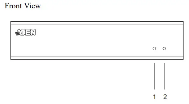
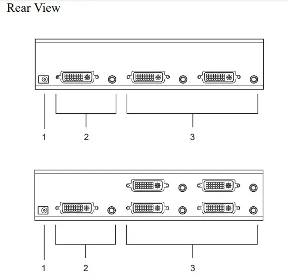
Components

| No. | Component | Description |
| 1 | Activity LED | Lights to indicate that there is a working DVI connection to the computer. |
| 2 | Power LED | Lights to indicate that the VS162 / VS164 is receiving power and is up and running. |
| No. | Component | Description |
| 1 | Power Jack | The power adapter cable plugs in here. |
| 2 | A/V Input Section | The cables from your source device’s DVI video and speaker ports plugin here. |
| 3 | A/V Output Section | The cables from your DVI monitors and speakers plugin here. |
Installation
- Make sure that the power to any device that you connect to the installation has been turned off. You must unplug the power cords of any computers that have the Keyboard Power On function.
- Make sure that all devices you will be installing are properly grounded.
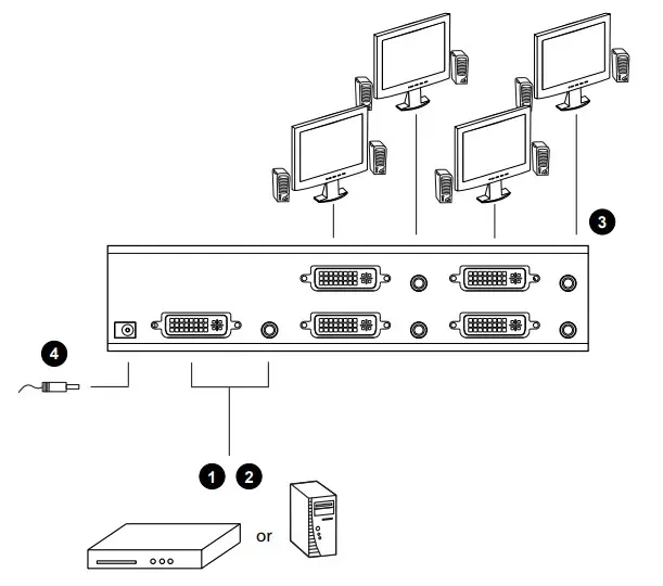
Single Stage
Refer to the installation diagram on the next page (the numbers in the diagram correspond to the numbers of the steps) and do the following:
- Use a male-to-male DVI cable to connect your source device’s DVI port to the VS162 / VS164’s Video In port.
- Use a male-to-male audio cable to connect your source device’s speaker port to the VS162 / VS164’s Audio In port.
- Plug your DVI monitors and speakers into the A/V Outports.
- Plug the power adapter that came with your switch into an AC power source, then plug the power adapter cable into the switch’s Power Jack.
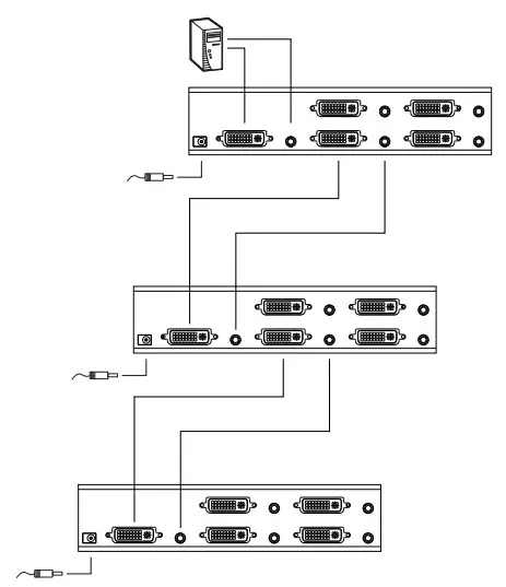
Cascading
To provide even more audio/video display, additional units can be cascaded from the VS162 / VS164’s A/V Outports. Simply use additional male-to-male DVI and audio cables to connect an A/V Out port on the parent splitter to the A/V In the port of the child splitter.
Recommended distances between devices in all cascade levels for transmitting a high-resolution signal are as follows:
Source to VS162 / VS164: 1.8 m
VS162 / VS164 to VS162 / VS164: 5 m
VS162 / VS164 to display: 5 m
- This product is for indoor use only.
- Read all of these instructions. Save them for future reference.
- Follow all warnings and instructions marked on the device.
- Do not place the device on an unstable surface (cart, stand, table, etc.). If the device falls, serious damage will result.
- Do not use the device near water.
- Do not place the device near, or over, radiators or heat registers.
- The device cabinet is provided with slots and openings to allow for adequate ventilation. To ensure reliable operation, and to protect against overheating, these openings must never be blocked or covered.
- The device should never be placed on a soft surface (bed, sofa, rug, etc.) as this will block its ventilation openings. Likewise, the device should not be placed in a built-in enclosure unless adequate ventilation has been provided.
- Never spill liquid of any kind on the device.
- Unplug the device from the wall outlet before cleaning. Do not use liquid or aerosol cleaners. Use a damp cloth for cleaning.
- The device should be operated from the type of power source indicated on the marking label. If you are not sure of the type of power available, consult your dealer or local power company.
- The device is designed for IT power distribution systems with 230V phase-to-phase voltage.
- To prevent damage to your installation it is important that all devices are properly grounded.
- The device is equipped with a 3-wire grounding-type plug.
- This is a safety feature. If you are unable to insert the plug into the outlet, contact your electrician to replace your obsolete outlet. Do not attempt to defeat the purpose of the grounding-type plug. Always follow your local/national wiring codes.
- Do not allow anything to rest on the power cord or cables. Route the power cord and cables so that they cannot be stepped on or tripped over.
- If an extension cord is used with this device make sure that the total of the ampere ratings of all products used on this card does not exceed the extension cord ampere rating. Make sure that the total of all products plugged into the wall outlet does not exceed 15 amperes.
- To help protect your system from sudden, transient increases and decreases in electrical power, use a surge suppressor, line conditioner, or uninterruptible power supply (UPS).
- Position system cables and power cables carefully; Be sure that nothing rests on any cables.
- Never push objects of any kind into or through cabinet slots. They may touch dangerous voltage points or short-out parts resulting in a risk of fire or electrical shock.
- Do not attempt to service the device yourself. Refer all servicing to qualified service personnel.
- If the following conditions occur, unplug the device from the wall outlet and bring it to qualified service personnel for repair.
♦The power cord or plug has become damaged or frayed.
♦Liquid has been spilled into the device.
♦The device has been exposed to rain or water.
♦The device has been dropped, or the cabinet has been damaged.
♦The device exhibits a distinct change in performance, indicating a need for service.
♦The device does not operate normally when the operating instructions are followed. - Only adjust those controls that are covered in the operating instructions. Improper adjustment of other controls may result in damage that will require extensive work by a qualified technician to repair.
Specifications
| Function | VS162 | VS164 | |
| Computer Connections | 2 | 4 | |
| Connectors | Video In | 1 x DVI port (F) | |
| Audio In | 1 x Audio jack | ||
| Video Out | 2 x DVI ports (F) | 4 x DVI ports (F) | |
| Audio Out | 2 x Audio jacks | 4 x Audio jacks | |
| Power | 1 x DC jack | ||
| LEDs | Activity | 1 | |
| Power | 1 | ||
| Resolution | Up to 1920 x 1200; DDC2B | ||
| Power Consumption | DC5.3V, 2.4W | DC5.3V, 4.0W | |
| Signal Range | 5 m (15 ft) | ||
| Environment | Operating Temp. | 0–50ºC | |
| Storage Temp. | -20–60ºC | ||
| Humidity | 0–80% RH, Non-condensing | ||
| Physical Properties | Housing | Metal | |
| Weight | 0.62 kg | 0.72 kg | |
| Dimensions (L x W x H) | 21.0 x 8.8 x 5.55 cm | ||
DVI Pin Assignments
| Pin | Signal | Pin | Signal |
| 1 | TMDS Data2- | 16 | Hot Plug Detect |
| 2 | TMDS Data2+ | 17 | TMDS Data0- |
| 3 | GND | 18 | TMDS Data0+ |
| 4 | N.C. | 19 | GND |
| 5 | N.C. | 20 | N.C. |
| 6 | DDC Clock | 21 | N.C. |
| 7 | DDC Data | 22 | TMDS Clock Shield |
| 8 | Analog Vertical Sync. | 23 | TMDS Clock+ |
| 9 | TMDS Data1- | 24 | TMDS Clock- |
| 10 | TMDS Data1+ | C1 | Analog Red |
| 11 | GND | C2 | Analog Green |
| 12 | N.C. | C3 | Analog Blue |
| 13 | N.C. | C4 | Analog H. Sync. |
| 14 | +5V Power | C5 | Analog Ground (Analog R, G, B Return) |
| 15 | Ground (return for +5V, H Sync., and V Sync.) |
Troubleshooting
| Symptom | Possible Cause | Action |
| Erratic behavior. | Unit not receiving enough power. | Use a DC 5.3V power adapter if you are not already using one. If you are already using a power adapter, check that it matches the system specifications (DC 5.3V), and that it is functioning properly. |
| Video doesn’t display on some ports. | DVI specification of the source device doesn’t match the DVI specification of the DVI cable and/or the DVI display device. | There are three DVI standards: DVI- A; DVI-D; and DVI-I. Make sure that the DVI specifications of the source device, cable and monitor all match. Note: Some monitors are able to support multiple DVI signals. |
| DVI-D only supports resolutions up to 1280 x 1024 | ||
| No DDC2B monitor on Port 1. | Since Port 1 is the port that supports DDC2B, there must be a monitor that supports DDC2B on Port 1. | |
| Port 1 monitor resolution set too high. | The resolution of the monitor on Port 1 must not exceed the maximum resolution of any of the other monitors. | |
| Port 1 monitor resolution not supported by other monitors. | The monitor on Port 1 must be set to a resolution that the other monitors support. | |
| Mixing of Apple Cinema Display and LCD monitors. | The monitors must all be Apple Cinema Display monitors or all LCD monitors. |
Limited Warranty
ATEN warrants its hardware in the country of purchase against flaws in materials and workmanship for a Warranty Period of two [2] years (warranty period may vary in certain regions/countries) commencing on the date of original purchase. This warranty period includes the LCD panel of ATEN LCD KVM switches.
Select products are warranted for an additional year (see A+Warranty for further details). Cables and accessories are not covered by the Standard Warranty.
What is covered by the Limited Hardware Warranty? ATEN will provide a repair service, without charge, during the Warranty Period. If a product is a detective, ATEN will, at its discretion, have the option to (1) repair said product with new or repaired components, or (2) replace the entire product with an identical product or with a similar product that fulfills the same function as the defective product. Replaced products assume the warranty of the original product for the remaining period or a period of 90 days, whichever is longer. When the products or components are replaced, the replacing articles shall become customer property and the replaced articles shall become the property of ATEN.
To learn more about our warranty policies, please visit our website:
http://www.aten.com/global/en/legal/policies/warranty-policy/
FCC Information
This equipment has been tested and found to comply with the limits for a Class B digital device, pursuant to Part 15 of the FCC Rules. These limits are designed to provide reasonable protection against harmful interference in a residential installation. This equipment generates, uses and can radiate radio frequency energy, and if not installed and used in accordance with the instruction manual, may cause interference to radio communications. However, there is no guarantee that interference will not occur in a particular installation. If this equipment does cause harmful interference to radio or television reception, which can be determined by turning the equipment off and on, the user is encouraged to try to correct the interference by one or more of the following measures:
- Reorient or relocate the receiving antenna;
- Increase the separation between the equipment and receiver;
- Connect the equipment into an outlet on a circuit different from that which the receiver is connected;
- Consult the dealer or an experienced radio/television technician for help.
FCC Caution: Any changes or modifications not expressly approved by the party responsible for compliance could void the user’s authority to operate this equipment. This device complies with Part 15 of the FCC Rules. Operation is subject to the following two conditions:
- this device may not cause harmful interference, and
- this device must accept any interference received, including interference that may cause undesired operation.
RoHS
This product is RoHS compliant.
SJ/T 11364-2006
The following contains information that relates to China.
Online Registration
| International | http://support.aten.com |
| North America | http://www.aten-usa.com/product_registration |
Telephone Support
| International | 886-2-8692-6959 |
| China | 86-400-810-0-810 |
| Japan | 81-3-5615-5811 |
| Korea | 82-2-467-6789 |
| North America | 1-888-999-ATEN ext 4988 |
| United Kingdom | 44-8-4481-58923 |
Technical Support
- For international online technical support – including troubleshooting, documentation, and software updates: http://support.aten.com
- For North American technical support
| Email Support | [email protected] | |
| Online Technical Support | Troubleshooting Documentation Software Updates | http://www.aten-usa.com/support |
| Telephone Support | 1-888-999-ATEN ext 4998 | |
Manual Part No. PAPE-1258-AT5G
 Printing Date: 2017-09-18
© Copyright 2017 ATEN® International Co., Ltd.
ATEN and the ATEN logo are registered trademarks of ATEN International Co., Ltd. All rights reserved.
All other brand names and trademarks are the registered property of their respective owners.