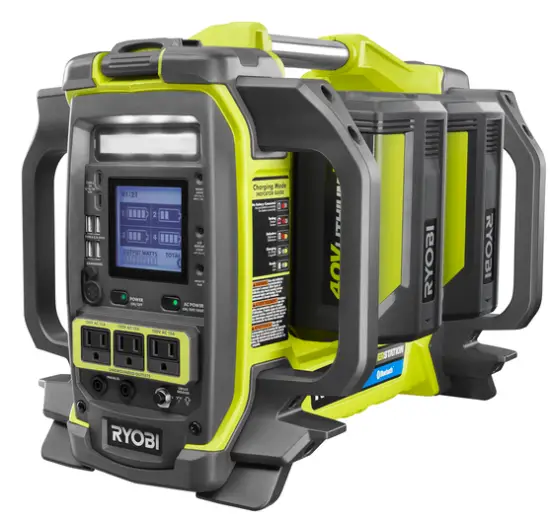
RYOBI RYi1802B6/RYi1802BT 40 VOLT POWER STATION
Parts
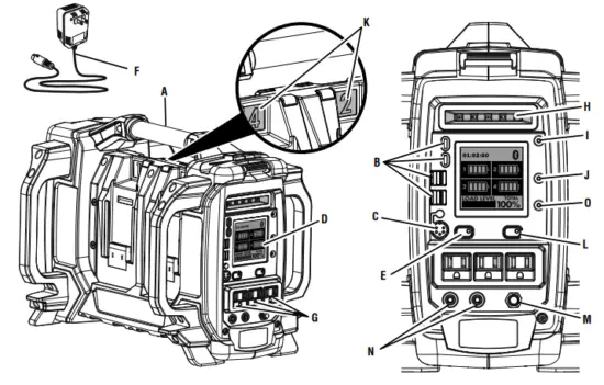
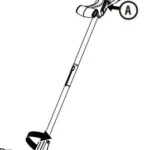
- Carry handle
- USB charging ports
- Charger input jack
- GENCONTROL™ display
- Main power button
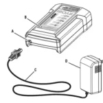
- Charger
- Battery pack
- Battery ports
- Latch
- LED
- High-temp charging
- Low-temp charging
- High-temp shutdown
- Low-temp shutdown
- High-temp reset
- Low-temp reset
- Low-voltage shutdown
- Low-voltage warning
- Overload warning
- Main power button
- AC output button
- AC receptacles
- LED task light
- Task light control button
pairing button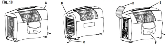
- Protective cover
- Vent opening
- Drawstring
- Panel access cover
SAFETY INSTRUCTIONS
- To reduce the risk of injury, close supervision is necessary when this product is used near children.
- Do not put fingers, hands, or foreign objects into the product.
- Use of an attachment not recommended or sold by the product manufacturer may result in a risk of fire, electric shock, or injury to persons.
- To reduce risk of damage to the electric plug and cord, pull by the plug rather than cord when disconnecting charger from the product.
- Do not use a battery pack or appliance that is damaged or modified. Damaged or modified batteries may exhibit unpredictable behavior resulting in fire, explosion or risk of injury.
- Do not operate the product with a damaged cord or plug, or a damaged output cable.
- Do not disassemble the product; take it to a qualified service person when service or repair is required. Incorrect reassembly may result in a risk of fire or electric shock.
- To reduce the risk of electric shock, unplug the product from the outlet before attempting any instructed servicing.
- To reduce risk of battery explosion, follow these instructions and those published by battery manufacturer and manufacturer of any equipment you intend to use in vicinity of the batteries. Review cautionary markings on the product.
- Do not expose the power station to rain or wet conditions. Water entering the power station will increase the risk of electric shock.
- Do not disassemble the product.
- For indoor use only.
- Store product indoors and away from children.
- As with all electrical devices, use caution when plugging and unplugging this unit into an outlet or plugging/unplugging other devices into this unit. Do not force this unit into an outlet. Do not force plugs into this unit.
- If this unit is used in a manner not specified by the manufacturer, the protection provided by this equipment may be impaired.
- Operate this product using only the AC power type listed in the product specifications.
- Do not force a polarized plug (one prong larger than the other) into this product. Flip plug over and retry.
- Risk of electric shock. When using a grounded appliance this tool will not provide an electrical path to earth ground.
- Do not power devices with damaged or frayed power cords.
- Never block air vents. Blocked vents may cause overheating. Product will automatically shut off when overheated.
- peeKproduct cool. Do not place near heat vents or in direct sunlight.
- Use only with the provided charger or a charger approved by the manufacturer.
- Do not use the product around flammable fumes and gasses, such as in the bilge of a boat or near propane tanks.
- Do not use the power station if it has been dropped or received a sharp blow. A damaged power source will increase the risk of fire.
- Use only in a dry location. Do not allow any liquid to get inside the power station or charger. Do not submerge the power station or charger in any liquid.
- Do not store the power station near fertilizers, gasoline, or other chemicals.
- Do not overload the power station. It must be used for powering devices less than the product rating.
- For use with RYOBI 40 V battery packs, see tool/appliance/battery pack/charger correlation supplement 988000-842.
- NEVER smoke or allow a spark or flame in vicinity of battery.
- Be extra cautious to reduce risk of dropping a metal tool onto product. It might spark or short-circuit battery or another electrical part that may cause explosion.
- Remove personal metal items such as rings, bracelets, necklaces, and watches when working with a battery. A battery can produce a short-circuit current high enough to weld a ring or the like to metal, causing a severe burn.
- When charging the internal battery, work in a well-ventilated area and do not restrict ventilation in any way.
- Under abusive conditions, liquid may be ejected from the battery; avoid contact. If contact accidentally occurs, Do not expose a power pack to fire or excessive temperature. Exposure to fire or temperature above 265°F may cause explosion.
- Have servicing performed by a qualified repair person using only identical replacement parts. This will ensure that the safety of the product is maintained.
- This inverter has not been tested for use with medical devices.
- Do not power life critical medical devices with this tool.
- This product should never be hard wired into a circuit.
- This product should never be wired into an AC distribution circuit.
- Save these instructions. Refer to them frequently and use them to instruct others who may use this product. If you loan someone this product, loan them these instructions also.
SAFETY RULES FOR CHARGER
- Before using battery charger, read all instructions and cautionary markings in this manual, on battery charger, battery, and product using battery to prevent misuse of the products and possible injury or damage.
- Do not use charger outdoors or expose to wet or damp conditions. Water entering charger will increase the risk of electric shock.
- Use of an attachment not recommended or sold by the battery charger manufacturer may result in a risk of fire, electric shock, or injury to persons. Following this rule will reduce the risk of electric shock, fire, or serious personal injury.
- Do not abuse cord or charger. Never use the cord to carry the charger. Do not pull the charger cord rather than the plug when disconnecting from receptacle. Damage to the cord or charger could occur and create an electric shock hazard. If cord or charger is damaged, have the charger replaced by an authorized serviceman.
- Make sure cord is located so that it will not be stepped on, tripped over, come in contact with sharp edges or moving parts or otherwise subjected to damage or stress. This will reduce the risk of accidental falls, which could cause injury, and damage to the cord, which could result in electric shock.
- Keep cord and charger from heat to prevent damage to housing or internal parts.
- Do not let gasoline, oils, petroleum-based products, etc. come in contact with plastic parts. They contain chemicals that can damage, weaken, or destroy plastic.
- An extension cord should not be used unless absolutely necessary. Use of improper extension cord could result in a risk of fire and electric shock. If extension cord must be used, make sure:
- Do not operate charger with a damaged cord or plug, which could cause shorting and electric shock. If damaged, have the charger replaced by an authorized serviceman.
- Do not operate charger if it has received a sharp blow, been dropped, or otherwise damaged in any way. Take it to an authorized serviceman for electrical check to determine if the charger is in good working order.
- Do not disassemble charger. Take it to an authorized serviceman when service or repair is required. Incorrect reassembly may result in a risk of electric shock or fire.
- Unplug charger from outlet before attempting any maintenance or cleaning to reduce the risk of electric shock.
- Disconnect charger from the power supply when not in use. This will reduce the risk of electric shock or damage to the charger if metal items should fall into the opening. It also will help prevent damage to the charger during a power surge.
- Risk of electric shock. Do not touch the uninsulated portion of output connector or uninsulated battery terminal.
- Do not use, store, or charge battery packs or products in locations where the temperature is less than -4°F or more than 113°F. Do not store outside or in vehicles.
- Save these instructions. Refer to them frequently and use them to instruct others who may use this tool. If you loan someone this tool, loan them these instructions also to prevent misuse of the product and possible injury.
SYMBOLS
| Les termes de mise en garde suivants et leur signification ont pour but d’expliquer le degré de risques associé à l’utilisation de ce produit. | ||
| SYMBOLE | SIGNAL | SIGNIFICATION |
 |
DANGER : | Indique une situation dangereuse qui, si elle n’est pas évitée, aura pour conséquences des blessures graves, voire mortelles. |
|
AVERTISSEMENT : | Indique une situation dangereuse qui, si elle n’est pas évitée, aura pour conséquences des blessures graves ou mortelles. |
|
ATTENTION : | Indique une situation dangereuse qui, si elle n’est pas évitée, pourrait entraîner des blessures légères ou de gravité modérée. |
|
AVIS : | (Sans symbole d’alerte de sécurité) Indique les informations jugées importantes sans toutefois représenter un risque de blessure (ex. : messages concernant les dommages matériels). |
ELECTRICAL
| Current in Amperes | Load in Watts | Maximum Allowable Cord Length | |||||
| At 120V | At 240V | #8 Wire | #10 Wire | #12 Wire | #14 Wire | #16 Wire | |
| 2.5 | 300 | 600 | 1000 ft. | 600 ft. | 375 ft. | 250 ft. | |
| 5 | 600 | 1200 | 500 ft. | 300 ft. | 200 ft. | 125 ft. | |
| 7.5 | 900 | 1800 | 350 ft. | 200 ft. | 125 ft. | 100 ft. | |
| 10 | 1200 | 2400 | 250 ft. | 150 ft. | 100 ft. | 50 ft. | |
| 15 | 1800 | 3600 | 150 ft. | 100 ft. | 65 ft. | ||
| 20 | 2400 | 4800 | 175 ft. | 125 ft. | 75 ft. | ||
| 25 | 3000 | 6000 | 150 ft. | 100 ft. | |||
| 30 | 3600 | 7200 | 125 ft. | 65 ft. | |||
| 40 | 4800 | 9600 | 90 ft. | ||||
ELECTRIC MOTOR LOADS
| Motor Size (H.P.) | Running Watts | Watts Required to Start Motor | ||
| Universal | Capacitor | Split Phase | ||
| 1/8 | 275 | N/A | 850 | 1200 |
| 1/6 | 275 | 600 | 850 | 2050 |
| 1/4 | 400 | 800 | 1050 | 2400 |
| 1/3 | 450 | 950 | 1350 | 2700 |
| 1/2 | 600 | 1000 | 1800 | 3600 |
| 3/4 | 850 | 1200 | 2600 | — |
| 1 | 1100 | N/A | 3300 | — |
Make sure the product can supply enough continuous (run- ning) and surge (starting) watts for the items you will power at the same time. Follow these simple steps.
- Select the items you will power at the same
- Total the continuous (running) watts of these items. This is the amount of power the product must produce to keep the items See the wattage reference chart at right.
- Estimate how many surge (starting) watts you will Surge wattage is the short burst of power needed to start electric motor-driven tools or appliances such as a circular saw or refrigerator. Because not all motors start at the same time, total surge watts can be estimated by adding only the item(s) with the highest additional surge watts to the total rated watts from step 2.
Tool or Appliance Running Watts* Starting Watts* Inflator Pump 50 150 Laptop 250 0 46 in. Flat Panel Television 190 0 Light (75 Watts) 75 0 565 Total Running Watts 150 Highest Starting Watts
POWER MANAGEMENT
- To prolong the life of the product and attached devices, it is important to take care when adding electrical loads to the product. There should be nothing connected to the product outlets before starting. The correct and safe way to manage product power is to sequentially add loads as follows:
- With nothing connected, press the main power button, then press the AC output button to power the AC
- Plug in and turn on the first load, preferably the largest load you have.
- Make sure the attached device operates
- Plug in and turn on the next
- Again, verify correct operation of the
- Repeat steps 4 and 5 for each additional
Never add more loads than the product capacity. Take special care to consider surge loads in product capacity as previously described.
| Application/Equipment | Estimated Running Watts* | Estimated Starting Watts* |
| Emergency / Home Standby | ||
| Lights (qty. 4 x 75 W) | 300 | 0 |
| Refrigerator | 600 | 780 |
| 46 in. Flat Panel Television | 190 | 0 |
| Satelite Receiver | 250 | 0 |
| Portable Fan | 40 | 120 |
| Heater | 1300 | 1300 |
| Laptop | 250 | 0 |
| Air Conditioner (10,000 BTU) | 600 | 1200 |
| Radio | 200 | 0 |
| Job Site | ||
| Electric Drill − 3/8 in. | 440 | 600 |
| Quartz Halogen Work Light | 1000 | 0 |
| Reciprocating Saw | 960 | 960 |
| Circular Saw − 7-1/4 in. | 1400 | 2300 |
| Miter Saw − 10 in. | 1800 | 1800 |
| Air Compressor − 1/4 HP | 970 | 1600 |
| Airless Sprayer − 1/3 HP | 600 | 1200 |
FEATURES
- Power Source.……………………………………………. 40 Volt DC
- Rated AC Output……………120 Volt AC, 60 Hz., 13.3 Amps (15.0 Amps for 3 min. Max)
Rated DC Output: - USB-A.……………………………….5 Volts, up to 2.1 Amps
- USB-C.…………………………5/12/20 Volts, up to 3 Amps
- Rated Output.……………..1,600 W (1,800 W for 3 min. Max)
- Starting Watts.……………………………………………….. 3,000 W
- Charger Input……………(nominal) 120V/60Hz AC only, 80 W
- Charging Time ……… Dependent on quantity and amp hour
- capacity of the battery pack(s)
- Operating Temp……………………………………………32°–104°F
KNOW YOUR PRODUCT
The safe use of this product requires an understanding of the information on the product and in this operator’s manual as well as a knowledge of the project you are attempting. Before use of this product, familiarize yourself with all operating features and safety rules. 120 V AC RECEPTACLES Your product has three single phase, 60 Hz outlets that are 120 Volt AC, 15 Amp receptacles. These can be used for operating appropriate appliances, electrical lighting, tools, and motor loads. AC OUTPUT BUTTON The AC output button is used to activate the 120V AC outlets when the power station is on. If an overload occurs, remove all loads, then press the AC output button again to reset. CARRY HANDLE The product is equipped with a carry handle for easy transport. The handle should be used to carry the product. CHARGER Using the charger before storing the power station helps keep the power station’s battery charged and ready at all times. GENCONTROL™ WITH BLUETOOTH® The GENCONTROL™ monitoring system with Bluetooth® tracks battery level, runtime, load, and other functions.
ASSEMBLY
UNPACKING
This product has been shipped completely assembled. n Carefully remove the product and any accessories from the box. Make sure that all items listed in the Packing List are included.
WARNING:
Do not use this product if it is not completely assembled or if any parts appear to be missing or damaged. Use of a product that is not properly and completely assembled could result in serious personal injury. n Inspect the product carefully to make sure no breakage or damage occurred during shipping. n Do not discard the packing material until you have carefully inspected and satisfactorily operated the product. n If any parts are damaged or missing, please call
PACKING LIST
Power Station Protective Cover Charger Cord and Adaptor Operator’s Manual WARNING: If any parts are damaged or missing do not operate this product until the parts are replaced. Use of this product with damaged or missing parts could result in serious personal injury.
WARNING:
Do not attempt to modify this product or create accessories not recommended for use with this product. Any such alteration or modification is misuse and could result in a hazardous condition leading to possible serious personal injury
OPERATION
APPLICATIONS
This product is designed to supply electrical power for operating compatible electrical lighting, appliances, tools, and motor loads.
SPECIAL REQUIREMENTS:
There may be General or State Occupational Safety and Health Administration (OSHA) regulations, local codes or ordinances that apply to the intended use of the product. Please consult a qualified electrician, electrical inspector, or the local agency having jurisdiction:
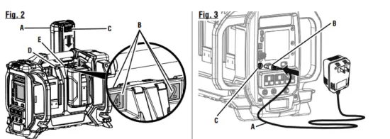
INSTALLING/REMOVING BATTERY PACKS
The power station has a total of four battery ports, but will function even if only one battery pack is installed. The more batteries installed, however, the greater the amount of power available and/or length of run or charge time provided, up to the full capacity noted in the Product Specifications section of this manual. For best performance, use at least two 5Ah or greater batteries.
Battery packs are shipped in a low charge condition and should be charged before first use. To install:
- Install the desired number of battery packs.
NOTE: If not using all of the available battery slots, the location of the batteries installed does not matter and will not affect power station charging performance. - Connect the charger cord to the power station, then plug the charger into a standard electrical outlet that is nominal 120/60 Hz AC (typical U.S. household type circuit).
- Once the charging cable is connected and plugged in, sequential charging of the batteries will begin.
NOTE: If connecting the charger immediately after using the power station at a high AC load, the battery temperature may be outside the acceptable charging range and cause the LCD display to show an error condition. If this occurs, charging will begin automatically once the battery temperature reaches an acceptable level.
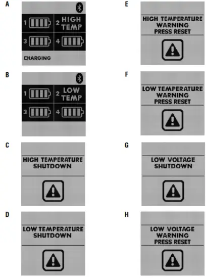
LED FUNCTIONS
| IF LCD DISPLAYS: | THE CONDITION IS: | TO RESOLVE: |
| HIGH TEMP or LOW TEMP when the battery is installed for charging.
See figures 4a – 4b. |
The battery you are charging is outside of the acceptable charging temperature range. | Allow the battery to reach acceptable tem- perature range. Battery may have to be removed from the port and reinstalled before charging will begin. |
| HIGH TEMPERATURE SHUTDOWN
or LOW TEMPERATURE SHUTDOWN. See figures 4c – 4d. |
The power station is outside of the acceptable operating temperature range. | Move the power station to a cooler or warmer area as needed and allow the unit to reach the acceptable temperature range. |
| HIGH TEMPERATURE WARNING or
LOW TEMPERATURE WARNING PRESS RESET. See figures 4e – 4f. |
The power station is nearing the maximum high or minimum low temperature acceptable to operate. | After allowing time for the power station to cool or warm to an acceptable temperature, press the reset button to continue operation. |
| LOW VOLTAGE SHUTDOWN.
See figure 4g. |
The power station’s batteries are discharged. | Charge the power station. If condition per- sists, the power station’s batteries should be replaced. |
| LOW VOLTAGE WARNING PRESS RESET.
See figure 4h. |
The power station’s batteries do not have sufficient charge to run the connected devices. | Disconnect some of the devices. If condi- tion persists, disconnect all devices and recharge the power station’s batteries. |
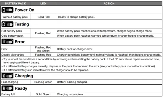
An LED light located at the top of each battery port will indicate the status of each battery. Refer to the Battery Port LED Functions chart for a description of the lights. In addition to the LED indicator, the LCD screen will also provide information about the battery and charging status of the power station.
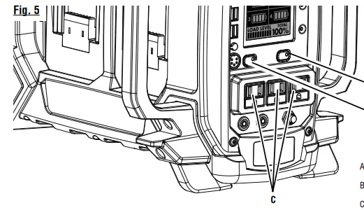
USING THE POWER STATION
See Figure 5.
To power the product on:
- Press and hold the main power button for two seconds to turn the product This will activate the LCD display and allow the USB charging ports and LED task light to be used.
NOTE: The main power button will illuminate when power to the unit is on.
To use the AC outlets:
- After powering the product on, press and hold the AC output button to activate the AC outlets.
NOTE: For normal operation of the power station, the main power button and the AC output button (if using AC outlets) will be solid green and there will be one audible beep. If any other light pattern or beeps occur, refer to the Alert Functions chart that follows.
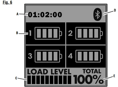
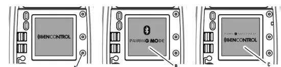
GENCONTROL™ LCD DISPLAY
NOTE: The LCD display will not work unless the product is powered on. Battery charge level: The battery charge level indicator shows how much charge is remaining in the battery. Load level: The load level indicator shows the connected load. If the product is approaching the maximum wattage/amperage capacity, the indicator will blink. If the load level capacity is exceeded, the LCD display will show OVERLOADED. Re-move all loads from the product and press the AC output button to reset (see fig. 5). Add loads back to the product one at a time, being careful not to exceed theproduct’s wattage rating. Run time: The LCD display shows the run time based on when the unit was switched on. Bluetooth®:Once paired, the LCD display indicates whether or not the GENCONTROL™ app is connected through Bluetooth®. Input charging power: The LCD display will show charging condition and full charge output.
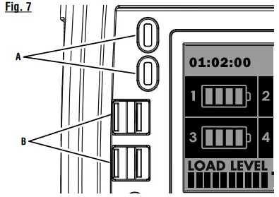
USB CHARGING PORTS
NOTE: The main power button must be on for the USB ports to be active. The USB-dedicated charging ports will charge most USB-compatible devices when used with the appropriate USB-A or USB-C cable (not provided). From the app store on your iOS or Android Bluetooth® enabled device, locate and install the RYOBI™ GENCONTROL™ app.
- Open the app and follow the directions as shown in the GENCONTROL™ app.
NOTE: Make sure Bluetooth® is enabled on your device. - Press the main power button on the power station to turn the LCD display on.
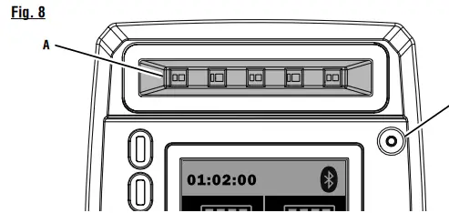
- Push and hold the “Hold to Pair” button to the right of the LCD panel on the product until the LCD panel displays “Pairing Mode.”
- The LCD screen on the product and the app on your device will indicate a successful pairing.
NOTE: If the product and app do not pair, make sure that “Pairing Mode” is displayed during the pairing process and that Bluetooth® is enabled on your device. - Press the menu icon in the top left corner of the app screen. This will show you the available features that can be controlled through the app. Install the cover over the power station as shown. NOTE: Make sure the vent opening is to the back of the unit and the front panel is visible through the panel access cover.
- Snug the protective cover around the unit by adjusting the drawstring to secure it.
- The panel access cover will unzip and allows you to adjust settings when using the protective cover.
- The handle zipper can be opened for carrying or moving the unit.
NOTE: Always keep zippers closed during storage to keep dust and liquids from entering into the unit.
MAINTENANCE
- GENERAL MAINTENANCE
Avoid using solvents when cleaning plastic parts. Most plastics are susceptible to damage from various types of commercial solvents and may be damaged by their use. Use clean cloths to remove dirt, dust, oil, grease, etc. WARNING: Do not at any time let brake fluids, gasoline, penetrating oils, etc., come in contact with plastic parts. Chemicals can damage, weaken, or destroy plastic which may result in serious personal injury. - STORING THE POWER STATION
Store indoors, without battery packs, in a dry, locked-up place, out of the reach of children. Store without battery packs unless actively charging/maintaining with the charger. Keep away from corrosive agents such as garden chemicals and de-icing salts.
TROUBLESHOOTING
| PROBLEM | POSSIBLE CAUSE | SOLUTION |
| Unit will not power on. | Battery is not charged.
Main power button released too quickly. |
Charge battery.
Press and hold main power button for two seconds. |
| AC receptacle does not work. | AC output is not active or AC power button released too quickly.
Item plugged in is defective. Power station is overloaded. |
Press and hold the AC output button for two seconds.
Try a different item. Remove loads and press the AC output button to reset. |
| Unit powers off unexpectedly. | Battery temperature is outside of normal operating thresholds.
Low or no battery charge. Battery fault. |
Battery operating temperature must be between -4˚F and 120˚F. The unit cannot be powered on until the temperature reaches normal operating thresholds. Allow the power station to warm or cool as needed.
Charge the battery. Units needs repair. Take to an autho- rized service center. |
| Charger is not working. | Battery temperature is outside the normal charging thresholds. | Battery charging temperature must be between 32˚F and 113˚F. Allow the pow- er station to warm or cool as needed, then charging will begin. |
| Power Station displays overload message when pulling less than the maximum load. | User exchanged batteries on the unit (removed and installed), at the same time. | Power Station load level should be be- low 40% (720 Watts) before exchanging batteries. |
| If problem persists after trying the above solutions, contact customer service or an authorized service center for assistance. | ||
FCC Statment
This device complies with part 15 of the FCC rules. Operation is subject to the following two conditions: (1) this device may not cause harmful interference, and (2) this device must accept any interference received, including interference that may cause undesired operation. NOTE: The grantee is not responsible for any changes or modifications not expressly approved by the party responsible for compliance. Such modifications could void the user’s authority to operate the equipment. NOTE: This equipment has been tested and found to comply with the limits for a Class B digital device, pursuant to part 15 of the FCC Rules. These limits are designed to provide reasonable protection against harmful interference in a residential installation. This equipment generates, uses and can radiate radio frequency energy and, if not installed and used in accordance with the instructions, may cause harmful interference to radio communications. However, there is no guarantee that interference will not occur in a particular installation. If this equipment does cause harmful interference to radio or television reception, which can be determined by turning the equipment off and on, the user is encouraged to try to correct the interference by one or more of the following measures: This device complies with Industry Canada license-exempt RSS standard(s). Operation is subject to the following two conditions: (1) this device may not cause interference, and (2) this device must accept any interference, including interference that may cause undesired operation of the device.
Under Industry Canada regulations, this radio transmitter may only operate using an antenna of a type and maximum (or lesser) gain approved for the transmitter by Industry Canada. To reduce potential radio interference to other users, the antenna type and its gain should be so chosen that the equivalent isotropically radiated power (e.i.r.p.) is not more than that necessary for successful communication.
SUPPLIER’S DECLARATION OF CONFORMITY
The responsible party declares that this device complies with Part 15 of the FCC Rules. Operation is subject to the following two conditions: (1) this device may not cause harmful interference, and (2) this device must accept any interference received, including interference that may cause undesired operation.
Report No.:
| Responsible Party: | One World Technologies |
| Address: | 115 Innovation Way, Anderson, SC 29621 |
| Telephone: | (864) 226-6511 |
| Fax: | (864) 965-6274 |
| Printed Name/Title: | John Collins / Director Regulatory |
Signature: |
|