behringer Digital Pro Mixer User Guide
DDM4000
Important Safety Instructions
![]()
- Read these instructions.
- Keep these instructions.
- Heed all warnings.
- Follow all instructions.
- Do not use this apparatus near water.
- Clean only with dry cloth.
- Do not block any ventilation openings. Install in accordance with the manufacturer’s instructions.
- Do not install near any heat sources such as radiators, heat registers, stoves, or other apparatus (including amplifiers) that produce heat.
- Do not defeat the safety purpose of the polarized or grounding-type plug. A polarized plug has two blades with one wider than the other. A grounding-type plug has two blades and a third grounding prong. The wide blade or the third prong are provided for your safety. If the provided plug does not fit into your outlet, consult an electrician for replacement of the obsolete outlet.
- Protect the power cord from being walked on or pinched particularly at plugs, convenience receptacles, and the point where they exit from the apparatus.
 Use only attachments/accessories specified by the manufacturer.
- Use only with the cart, stand, tripod, bracket, or table specified by the manufacturer, or sold with the apparatus. When a cart is used, use caution when moving the cart/apparatus combination to avoid injury from tip-over.
- Unplug this apparatus during lightning storms or when unused for long periods of time.
- Refer all servicing to qualified service personnel. Servicing is required when the apparatus has been damaged in any way, such as power supply cord or plug is damaged, liquid has been spilled or objects have fallen into the apparatus, the apparatus has been exposed to rain or moisture, does not operate normally, or has been dropped.
- The apparatus shall be connected to a MAINS socket outlet with a protective earthing connection.
- Where the MAINS plug or an appliance coupler is used as the disconnect device, the disconnect device shall remain readily operable.
 Correct disposal of this product: This symbol indicates that this product must not be disposed of with household waste, according to the WEEE Directive (2012/19/EU) and your national law. This product should be taken to a collection center licensed for the recycling of waste electrical and electronic equipment (EEE). The mishandling of this type of waste could have a possible negative impact on the environment and human health due to potentially hazardous substances that are generally associated with EEE. At the same time, your cooperation in the correct disposal of this product will contribute to the efficient use of natural resources. For more information about where you can take your waste equipment for recycling, please contact your local city office, or your household waste collection service.
- Do not install in a confined space, such as a book case or similar unit.
- Do not place naked flame sources, such as lighted candles, on the apparatus.
- Please keep the environmental aspects of battery disposal in mind. Batteries must be disposed-of at a battery collection point.
- This apparatus may be used in tropical and moderate climates up to 45°C.
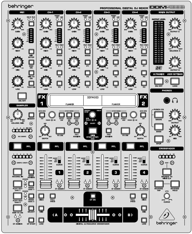
DIGITAL PRO MIXER DDM4000 Controls

- Stereo channels 1 – 4

- Microphone channel

- Crossfader section
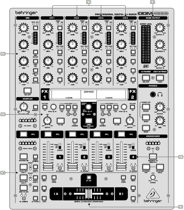
- Main and phones section
- Sampler
- BPM and effects section
Controls
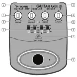
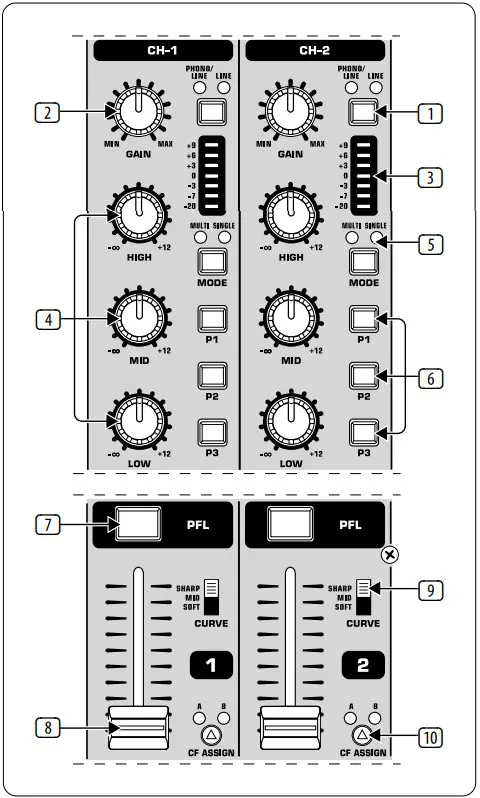
- The input select switch lets you switch between two signal sources. Select Line to hear the signal of the Line input (67). Select Phono/Line to listen to the incoming source signal at the Phono/Line (68) input.
- The GAIN knob adjusts the level of the input signal. The actual level is displayed on the level meter (3).
- The 7-segment LED meter indicates the level of the input signal.
- Each input channel features a 3-band equalizer (HIGH, MID and LOW) with kill feature, giving you up to 12 dB of boost and a maximum cut of -∞ dB (kill). The kill feature lets you mute the given frequency range. When each EQ knob is turned fully left, the signal is effectively muted. All EQ parameters can be adjusted in Channel Setup.
- The MODE push button changes the functionality of the preset push button
- from Multi to Single.
- The preset push buttons P1, P2 and P3 allow you to store and activate equalizer presets. When activated in Single Mode, these push buttons provide a maximum cut of -∞ dB (kill function).
- Press the PFL push button to listen in on the channel’s signal using headphones.
- The fader controls the channel volume.
- The CURVE switch adjusts the response of the fader. In SOFT Mode, the fader responds slower to steady fader movement in the upper range and quicker in the lower range. In SHARP Mode, the fader adjusts the volume quicker in the upper third and slower in the lower range. In MID Mode, the fader responds in a linear fashion. Since a difference in volume levels is heard when switching between modes, don’t use this switch while playing music!
- The CF ASSIGN push button lets you determine on which side of the crossfader (20) (A or B) the signal is to be heard.
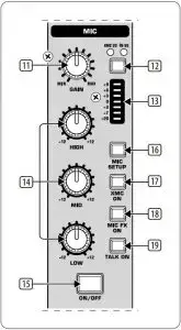
- The GAIN knob adjusts the level of the microphone signal at the MIC 1 input.
- This switch determines which signal is to be displayed on the level meter (13). IN VU shows the unprocessed input level which helps you to adjust the microphone signal correctly. XMC VU shows the level after it has passed the Ultramic processor.
- The 7-segment LED meter indicates the level of the microphone channel.
- The microphone channel strip features a 3-band equalizer (HIGH, MID and LOW). The range is ±12 dB.
- The ON/OFF push button turns the microphone channel on and off.
- The MIC SETUP push button opens the Mic Setup menu on the display. This allows you to adjust the settings of the equalizer, the Ultramic processor and the MIC FX (effects processor).
- The XMC ON push button activates the ULTRAMIC processor, which includes a 2-band compressor and expander. Ultramic settings can be adjusted in Mic Setup.
- The MIC FX ON push button activates the microphone effects processor. Select the effect in Mic Setup.
- The TALK ON push button activates the Talkover function. This attenuates the volume level of the music as soon as you speak into the microphone. This is a very useful function to make yourself heard over the music being played. You can adjust all the relevant settings in Talk Setup.
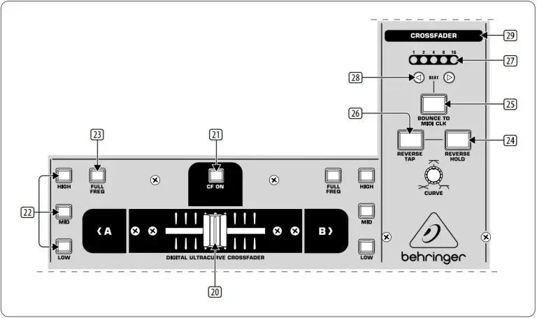
- The replaceable crossfader is used to fade between the signals that are assigned to its two sides A and B. You can assign the stereo channels and sampler using the CF Assign push buttons (10) and (65).
- The CF ON push button activates the crossfader. When the push button is not pressed, the signals of the individual channels are routed straight to the Main outputs.
- There are 3 Kill push buttons (HIGH, MID and LOW) on each side of the crossfader which let you mute the given frequency range. In Crossfader Setup, it is possible to activate a special X-OVER mode that enhances the crossfader’s functionality in combination with the Kill push buttons.
- Press the FULL FREQ push button to remove any frequency cuts of the KILL EQ (22).
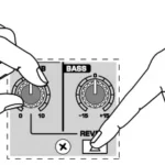
- The CURVE knob lets you seamlessly adjust the response of the crossfader. The REVERSE function allows you to reverse the configuration of the crossfader. This way you can toggle between Channel A and B at the flick of a switch.
- REVERSE HOLD activates a permanent Reverse function. The crossfader fades between sides A and B in the reverse direction. This means that A is now on the right and B on the left side.
- REVERSE TAP activates a momentary Reverse function. This means that A and B are interchanged as long as the TAP push button is held down.
- Press the BOUNCE TO MIDI CLK push button to activate the bouncing. Once the push button is pressed, the signal repeatedly jumps from A to B and back again corresponding to the interval pre-selected by using the BEAT push buttons (28).
- The BEAT push buttons let you determine the Bounce rate, which can range between one and 16 beats.
- These LEDs indicate the number of beats you have chosen.
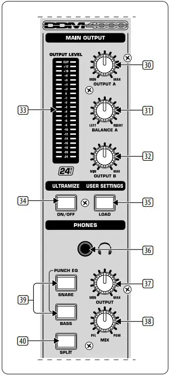
- The OUTPUT A knob controls the volume of output A ((73)).
- The BALANCE knob adjusts the stereo panning of output A.
- The OUTPUT B knob controls the volume of output B ((74)).
- The high-resolution, 22-segment OUTPUT LEVEL meter indicates the level of the output signal on OUTPUT A.
- ULTRAMIZE ON/OFF push button:The Ultramizer is an effect that enhances the loudness and assertiveness by dynamic compression. In Ultramizer Setup, you can configure the Ultramizer.
- The LOAD push button lets you load the user settings of the entire mixer. The settings that are active when the device is turned off are loaded when the device is switched back on again.
- Connect the headphones to the PHONES jack (1/4″ TRS connector).
- The OUTPUT knob controls the volume of the head-phones.
- The MIX knob adjusts the balance between PFL signal and PGM signal (PFL = Pre Fader Listening, fader independent pre-listening of individual channels; PGM = Program, Master signal). When the knob is turned completely to the left, you only hear the PFL signal, whereas when turned completely to the right the Master signal is heard. Between these two positions, you can adjust the mix of both signals.
- The PUNCH EQ function helps synchronize two tracks. You can orient yourself to the snare or the bass drum or both. Press the SNARE or BASS push button to emphasize the selected sound in the headphones.
- When the SPLIT push button is pressed, the PFL signal is heard in the left headphone and the PGM signal is only heard in the right headphone.
- The graphic display shows BPM values, effect names and effect parameters as well as channel assignments. It also leads you through Console Setup.
- The FX ON push button activates the effects unit.
- Press the FX ASSIGN push button to assign an effects unit to a signal source (push button flashes). The possible input sources are listed on the display. Select the preferred source by turning and pressing the PARAMETER knob (45).
- The DEPTH knob adjusts the effect intensity (depth). For some effects, it also lets you adjust the mix between the original signal (dry) and the effect signal (wet).
- Press the PARAM (eter) knob to select the effect parameters. By turning the knob, you can change the parameter shown on the display.
- Press SELECT/LOW to access the effects list (on the display). Turn and press the knob (45) to load a preset.
- Press the PARAM/MID push button to access the effect parameters. Turn the knob (45) to change the parameter value.
- Press DEFAULT/HIGH to restore a preset.
- Depending on the selected effect, the BEAT push buttons can adjust time related parameters. However, the values entered are not in milliseconds or similar units, but in beats.
- To enter the tempo manually, tap this push button (at least 2x) in the rhythm of the music (TAP). By keeping the AUTO BPM/TAP push button pressed a little longer (> 1 s), the automatic tempo input (AUTO BPM) is reactivated.
- Turn the CONSOLE SETUP knob to adjust the tempo of the MIDI Clock (press and turn simultaneously = coarse adjustment). A short press on the knob confirms the entry made. A long press on the knob lets you access Console Setup.
- The MIDI START/STOP/ESC turns on the MIDI Clock.
- The ADJUST push buttons let you transfer the tempo of the BPM counter to the MIDI Clock.
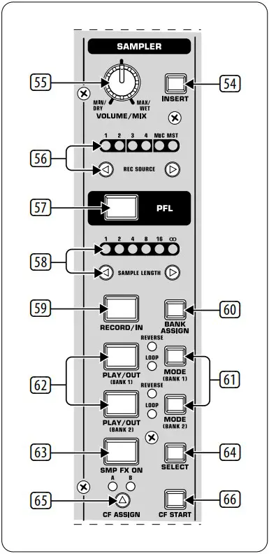
- Press the INSERT push button to add the sampler signal to the channel (Insert Mode). If the push button is not activated, the sampler is mixed to the selected channel (Mix Mode). In both cases, playback is initiated with the REC SOURCE push buttons. When the sampler is routed to the crossfader, the LED of the INSERT push button goes out.
- The VOLUME/MIX knob controls the volume of the sampler (in Mix Mode) as well as the volume balance between input signal and Sampler (in Insert Mode).
- The REC SOURCE push buttons let you select the channel for recording and playing back samples.
- Press the PFL push button to listen in on the sampler signal with the headphones.
- SAMPLE LENGTH adjusts the recording time (1–16 beats or endless recording ∞).
- RECORD/IN lets you record to the Sampler. Select a bank beforehand. By pressing the push button a second time, the recording is stopped (only in ∞ Mode).
- BANK ASSIGN is used to select a bank in which the recorded material is stored. The selected bank is indicated by the relevant MODE push button (61) which signalizes the readiness to record.
- The MODE push buttons (Bank 1 and Bank 2) are used to select the sampler’s types of playback (Reverse and Loop). A short tap activates or deactivates the Reverse function; pressing the push button a little longer activates or deactivates the Loop function.
- Press the PLAY/OUT push button to start the playback of the recorded sample. When the Loop function is deactivated, the sample is only played back as long as the PLAY push button is pressed.
- Press SMP FX ON push button to activate the Brake effect.
- Press the SELECT push button to determine the length of the brake (1, 4 or 8 Beat Brake, which is shown in the center of the display).
- The CF ASSIGN push button lets you determine on which side of the crossfader the sampler signal is to be routed to.
- You can even trigger the sampler with the crossfader when the sampler is assigned to it. To order to do so, simply press the CF START push button. But beforehand, use BANK ASSIGN to select the bank that should be played back when using the fader.
- The LINE inputs are used to connect the Line signals (for example, CD players, sound cards and drum machines).
- The PHONO inputs let you connect turntables.
- Use the PHONO/LINE switches to set the PHONO inputs to Line level in order for you to be able to connect a CD player to the PHONO inputs.
- The GND connectors are used to ground the turntables.
- The balanced XLR connectors provide a connection for dynamic microphones.
- This is the LEVEL control for the MIC 2 input.
- These are the OUT A outputs (XLR) allowing you to connect to an amplifier. Use the OUTPUT A control (30) to adjust the volume level. Additionally, the SUBWOOFER output lets you hook up a subwoofer. A crossover is integrated into the DDM4000. The crossover frequency is adjusted in Output Setup.
- The MAIN OUT connector panel consists of OUT A, OUT B and TAPE outputs.
- DIGITAL OUT is the digital output of the DDM4000. This is where you find the TAPE signal in CD quality (16 bit/44.1 kHz).
- These are the MIDI IN, MIDI OUT and MIDI THRU connectors that allow you to connect external MIDI equipment and synchronize with their MIDI Clock.
- Power is supplied via an IEC connector. The matching cable is provided with the unit.
- FUSE RETAINER/VOLTAGE SELECTOR.
- Use the POWER switch to turn on the DDM4000. Before connecting the unit to the power mains, ensure that the POWER switch is in OFF position. When the unit is in operation, ensure that the mains plug is accessible.
Specifications
| Audio Inputs | |
| Mic 1/2 (XLR, Electronically Balanced) | |
| Max. input level | -14 dBu |
| Input impedance | 2 kΩ |
| Phono (RCA) | |
| Max. input level | -18 dBu |
| Input impedance | 47 kΩ |
| Line (RCA) | |
| Max. input level | +30 dBu |
| Input impedance | 15 kΩ |
| Audio Outputs | |
| Max. output level | +21 dBu |
| Output impedance | 200 Ω |
| OUT A/OUT B/TAPE (RCA) | |
| Max. output level | +21 dBu |
| Output impedance | 100 Ω |
| Phones Out | max. 260 mW @ 100 Ω / 1% THD |
| S/PDIF | (coaxial, 16 bit, 44.1 kHz) |
| Equalizer | |
| Stereo Low | -∞ dB/+12 dB |
| Stereo Mid | -∞ dB/+12 dB |
| Stereo High | -∞ dB/+12 dB |
| Mic Low | -12 dB/+12 dB, Shelving |
| Mic Mid | -12 dB/+12 dB, Peak |
| Mic High | -12 dB/+12 dB, Shelving |
| Digital Effects Processor | |
| DSP | 2x Analog Devices Black Fin |
| AD/DA converter | 24-bit Sigma-Delta
128-times oversampling/Cirrus |
| Sampling rate | 44.1 kHz |
| LCD display | 320 x 40 pixel |
| MIDI Interface | 5-pin DIN jacks In/Out/Thru |
| System Specifications | |
| Frequency Response | |
| Mic | 25 Hz – 20 kHz, +0/-3 dB |
| Phono | 20 Hz – 20 kHz, +0/-3 dB |
| Line | 20 Hz – 20 kHz, +0/-3 dB |
| Signal-to-Noise Ratio | |
| Mic | > 87 dB |
| Phono | > 83 dB |
| Line | > 102 dB |
| Distortion (THD) | < 0,009% (Line – OUT A) |
| Crosstalk | < -80 dB / 1 kHz (Line) |
| Power Supply | |
| Mains Voltage/Fuse | |
| 100 – 240 V~, 50/60 Hz | T 1 A H 250 V |
| Power Consumption | max. 20 W |
| Mains Connector | standard IEC receptacle |
| Dimensions/Weight | |
| Dimensions (H x W x D) |
|
| Weight | approx. 12.3 lbs / 5.6 kg |
Other important information
- Register online. Please register your new MusicTribe equipment right after you purchase it by visiting musictribe.com. Registering your purchase using our simple online form helps us to process your repair claims more quickly and efficiently. Also, read the terms and conditions of our warranty, if applicable.
- Malfunction. Should your MusicTribe Authorized Reseller not be located in your vicinity, you may contact the MusicTribe Authorized Fulfiller for your country listed under “Support” at musictribe.com. Should your country not be listed, please check if your problem can be dealt with by our “Online Support” which may also be found under “Support” at musictribe.com. Alternatively, please submit an online warranty claim at musictribe.com BEFORE returning the product.
- Power Connections. Before plugging the unit into a power socket, please make sure you are using the correct mains voltage for your particular model. Faulty fuses must be replaced with fuses of the same type and rating without exception.
LEGAL DISCLAIMER
Music Tribe accepts no liability for any loss which may be suffered by any person who relies either wholly or in part upon any description, photograph, or statement contained herein. Technical specifications, appearances and other information are subject to change without notice. All trademarks are the property of their respective owners. Midas, Klark Teknik, Lab Gruppen, Lake, Tannoy, Turbosound, TC Electronic, TC Helicon, Behringer, Bugera, Oberheim, Auratone and Coolaudio are trademarks or registered trademarks of Music Tribe Global Brands Ltd. © Music Tribe Global Brands Ltd. 2021 All rights reserved.
LIMITED WARRANTY
For the applicable warranty terms and conditions and additional information regarding Music Tribe’s Limited Warranty, please see complete details online at musictribe.com/warranty.
FEDERAL COMMUNICATIONS COMMISSION COMPLIANCE INFORMATION
Behringer DIGITAL PRO MIXER DDM400
Responsible Party Name: Music Tribe Commercial NV Inc.
Address: 5270 Procyon Street, Las Vegas NV 89118, United States
Phone Number: +1 702 800 8290
DIGITAL PRO MIXER DDM4000
This equipment has been tested and found to comply with the limits for a Class B digital device, pursuant to part 15 of the FCC Rules. These limits are designed to provide reasonable protection against harmful interference in a residential installation. This equipment generates, uses and can radiate radio frequency energy and, if not installed and used in accordance with the instructions, may cause harmful interference to radio communications. However, there is no guarantee that interference will not occur in a particular installation. If this equipment does cause harmful interference to radio or television reception, which can be determined by turning the equipment off and on, the user is encouraged to try to correct the interference by one or more of the following measures:
- Reorient or relocate the receiving antenna.
- Increase the separation between the equipment and receiver.
- Connect the equipment into an outlet on a circuit different from that to which the receiver is connected.
- Consult the dealer or an experienced radio/TV technician for help.
This device complies with Part 15 of the FCC rules. Operation is subject to the following two conditions:
- this device may not cause harmful interference, and
- this device must accept any interference received, including interference that may cause undesired operation.
Important information:
Changes or modifications to the equipment not expressly approved by Music Tribe can void the user’s authority to use the equipment.
Hereby, Music Tribe declares that this product is in compliance with Directive 2014/35/EU,Directive 2014/30/EU, Directive 2011/65/EU and Amendment 2015/863/
EU, Directive 2012/19/EU, Regulation 519/2012 REACH SVHC and Directive 1907/2006/EC.
Full text of EU DoC is available at https://community.musictribe.com/
EU Representative: Music Tribe Brands DK A/S
Address: Ib Spang Olsens Gade 17, DK – 8200 Aarhus N, Denmark