Behringer X32 Producer Digital Mixer Quick Start Guide

X32 PRODUCER DIGITAL MIXER
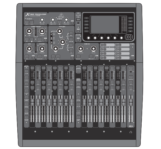
40-Input, 25-Bus Rack-Mountable Digital Mixing Console with
16 Programmable Midas Preamps, 17 Motorized Faders,
32-Channel Audio Interface and iPad/iPhone Remote Control
![]()
Important Safety Instructions


To reduce the risk of electric shock, do not remove the top cover (or the rear section). No user serviceable parts inside. Refer servicing to qualified personnel.
To reduce the risk of fire or electric shock, do not expose this appliance to rain and moisture. The apparatus shall not be exposed to dripping or splashing liquids and no objects filled with liquids, such as vases, shall be placed on the apparatus.
These service instructions are for use by qualified service personnel only. To reduce the risk of electric shock do not perform any servicing other than that contained in the operation instructions. Repairs have to be performed by qualified service personnel.
- Read these instructions.
- Keep these instructions.
- Heed all warnings.
- Follow all instructions.
- Do not use this apparatus near water.
- Clean only with dry cloth.
- Do not block any ventilation openings. Install in accordance with the manufacturer’s instructions.
- Do not install near any heat sources such as radiators, heat registers, stoves, or other apparatus (including amplifiers) that produce heat.
- Do not defeat the safety purpose of the polarized or grounding-type plug. A polarized plug has two blades with one wider than the other. A grounding-type plug has two blades and a third grounding prong. The wide blade or the third prong are provided for your safety. If the provided plug does not fit into your outlet, consult an electrician for replacement of the obsolete outlet.
- Protect the power cord from being walked on or pinched particularly at plugs, convenience receptacles, and the point where they exit from the apparatus.
- Use only attachments/accessories specified by the manufacturer.

- Unplug this apparatus during lightning storms or when unused for long periods of time.
- Refer all servicing to qualified service personnel. Servicing is required when the apparatus has been damaged in any way, such as power supply cord or plug is damaged, liquid has been spilled or objects have fallen into the apparatus, the apparatus has been exposed to rain or moisture, does not operate normally, or has been dropped.
- The apparatus shall be connected to a MAINS socket outlet with a protective earthing connection.
- Where the MAINS plug or an appliance coupler is used as the disconnect device, the disconnect device shall remain readily operable.

- Do not install in a confined space, such as a book case or similar unit.
- Do not place naked flame sources, such as lighted candles, on the apparatus.
- Please keep the environmental aspects of battery disposal in mind. Batteries must be disposed-of at a battery collection point.
- Use this apparatus in tropical and/or moderate climates.


LEGAL DISCLAIMER
Music Tribe accepts no liability for any loss which may be suffered by any person who relies either wholly or in part upon any description, photograph, or statement contained herein. Technical specifications, appearances and other information are subject to change without notice. All trademarks are the property of their respective owners. Midas, Klark Teknik, Lab Gruppen, Lake, Tannoy, Turbosound, TC Electronic, TC Helicon, Behringer, Bugera, Auratoneand Coolaudio are trademarks or registered trademarks of Music Tribe Global Brands Ltd. © Music Tribe Global Brands Ltd. 2020 All rights reserved.
LIMITED WARRANTY
For the applicable warranty terms and conditions and additional information regarding Music Tribe’s Limited Warranty, please see complete details online at musictribe.com/warranty.
Getting Started

Mixer Operational Overview
Welcome to the X32 PRODUCER digital mixing console Quick Start Guide! This document will give you an overview of the basic operations of the mixer, allowing you to get up and running quickly. While reading through the information in this document, we encourage you to experiment with the console’s different screens and controls. The console’s user interface was designed to be extremely easy to navigate through and learn. In addition to this Quick Start Guide, there is an English user manual available as a PDF download from behringer.com.
General user interface operation
The X32 PRODUCER user interface is divided into five major sections:
- Channel Strip and Monitoring
- Input Channels
- Display
- Group/Bus/Main Channels
- Various Assignments
View buttons rule
Throughout the top panel of the console, you will find small buttons labeled View. Press these buttons to immediately switch the console’s large color display (known as the Main Display) to show information related to the section whose View button you have just pressed.
For example, if you are editing the equalizer and feel like seeing a large display of the EQ frequency response curve or corresponding EQ parameter value, simply press the adjacent View button in the EQ section. If you need to check where the monitor signal is being routed, simply press the View button next to the Phones Level knob and the main display will show the details.
With the View button approach of the X32 PRODUCER console, there is almost never a need to drill down through multiple menu pages, since the View buttons will always take you directly to the relevant screen.
Tip: The Setup/Global tab on the main display allows preferences for the behavior of View and Select buttons to be adjusted.
Customizing the X32 PRODUCER through the Utilities page
Press the Utility button, located to the right of the main display, to bring up useful functions in a “context-sensitive” manner. For example:
- When you are adjusting the equalizer of a console channel, pressing the Utility button will offer copying, pasting, loading or saving of equalizer settings
- Pressing the Utility button while holding a channel select button depressed will present a naming screen where you can customize the channel’s appearance on both the main display as well as the small channel display
- On the Routing pages, pressing the Utility button will offer loading or saving different presets of routing scenarios
- In the Scenes menu, pressing the Utility button offers copying, loading, saving or naming console scenes
Sometimes there is more to say

Some of the individual pages on the main display contain more adjustable parameters than can be controlled by the 6 rotary push encoders located beneath it. In these cases there is a small page number indication, e.g. “1/2”. Simply press the Layer Up/Down buttons to switch between layers.

Section 1: Channel Strip and Monitoring
The X32 PRODUCER’s channel strip offers dedicated controls for the most important processing parameters of the currently selected channel. To adjust controls for a given channel strip, simply press the Select button on the desired input or output channel.
Certain sections of the channel strip (such as the low cut filter, noise gate, EQ and compressor) contain a respectively labeled button that can be pressed to switch the specific effect on and off. The button illuminates to show the effect is active, and goes dark when bypassed.
Within the channel strip, the rotary control knobs are surrounded by an amber LED collar that indicates the parameter’s value. Whenever this backlit knob is turned off, it indicates that this specific control/parameter is not available for the selected channel type. For example, if an output bus is currently selected, the LED collar and the gain knob are turned off, because there is no input gain to be controlled on an output bus.
The channel strip consists of the following sub-sections:
- Config/Preamp
- Gate, Dynamics
- Equalizer
- Main Bus
Each of these subsections correspond to the processing steps of the currently selected channel, and they each have their own View button that, when pressed, switches the Main Display to a page displaying all related parameters for that subsection.
Monitoring and Talkback
There are two separate Level controls in this section, one for the headphone output located at the front of the console, and a second one for the monitor outputs located on the rear panel.
Press the section’s View button to edit various monitoring preferences, such as the input source for the phones bus and the monitor outputs.
This section also contains independent Talkback buttons (A and B). Press the View button next to the Phones Level knob, then press Page Select right to access the Talkback A and B edit pages.

Section 2: Input Channel Banks
You will find a select button on top of every channel that is used to direct the control focus of the user interface, including all channel related parameters (channel strip and main display), to that channel. Please note that at any time, there is exactly one channel selected (either Input Ch 1-32, Aux 1-6/USB, FX Returns 1L-4R, Mix Bus 1-16, Main LR/C, or Matrix 1-6). DCA Groups (digitally controlled amplifier) cannot be selected because they control a number of assigned channels rather than one specific channel.
The Input Channels section of the console is located on the left hand side, and offers 8 separate input channel strips. These 8 channel strips represent six separate layers of inputs for the console, including:
- Input Channels 1-8
- Input Channels 9-16
- Input Channels 17-24
- Input Channels 25-32
- Aux Inputs 1-6/USB playback
- Effects Returns
Press any of the correspondingly labeled layer buttons on the left side of the console to switch the input channel bank to any of the six layers listed above. The button will illuminate, reminding you which layer is active.
Two more layers (Bus Master 1-8 and 9-16) are also offered, allowing you to adjust the levels of the 16 Mix Bus Masters, which is useful when you wish to include Bus Masters into DCA Group assignments.
On each fader strip you will find a motorized 100 mm level fader, Mute and Solo buttons, a Gate indicator, an input level meter, Compressor indicator, and the channel select button.

The main color display presents information about various sections of the console. It can be switched to different screens using the console’s View buttons, as well as any of the 10 buttons on either side of the display.
The top section of the main display permanently covers useful status information. The top left corner shows the selected channel number, its nickname and the selected icon. The next block shows the current scene number and name in amber, as well as the next upcoming scene. The center section displays the playback file name along with elapsed and remaining time and a recorder status icon. The next block to the right has 4 segments to show the status of AES50 ports A and B, the Card slot and the audio clock synchronization source and sample rate (top right). Small green square indicators show proper connectivity. The right most block shows the console time that can be set under Setup/Config.
When working with any given screen, press the Page keys located on the display bezel to switch to different screen pages.
Editing parameters or settings on each of the screens is done using the 6 associated push-encoders along the bottom edge of the display.
- Whenever there is a continuous control or list entry, you can turn the corresponding knob for editing, which is indicated by various circular icons
- When there is a switch or toggle function on one of these knobs, you will see a broad rectangular button along the lower edge of the field. Pressing the encoder changes the on/off state of the corresponding function. When the rectangular button in the display is dark grey, the corresponding function is off/inactive; when it is amber, the function is on/active

Section 4: Group/Bus Channel Banks
This section of the console offers eight channel strips, divided into the following layers:
- Eight DCA (digitally controlled amplifier) groups
- Mix Bus masters 1-8
- Mix Bus masters 9-16
- Matrix Outputs 1-6, and the main center bus
This section also contains a main LR output fader, which is independent and always available no matter which channel bank or layer is active.
When using the DCA Groups layer, the DCA Groups can be soloed and muted, but they cannot be selected. To edit the DCA group names, icons and colors, navigate to the Setup/DCA Groups page on the main display. DCA group names, icons and color can also be edited by pressing the Utility and Select button concurrently. Once the Setup/scribble strip page is open you can directly select any other channel for editing its layout in the same run.
When using any of the output bus layers, note that the bottom LEDs on the meters in this section illuminate when the respective bus is fed from pre-fader sources of the selected channel.
Section 5: Various Assignments
- Assigning DCA Groups
Thanks to the two distinct fader groups (inputs on the left, outputs on the right), the task of assigning channels or buses to a virtual DCA Group is a breeze on the X32 PRODUCER. Simply hold the respective DCA Group Select button on the right-hand side of the console, while pressing the Select buttons for all the input channels that you wish to assign to said DCA Group. You can also press the DCA Group Select button in order to check which channels are already assigned to it. The assigned channel Select buttons will light up.
- Custom Assignable Controls:
The Assign section of the console offers three banks of 8 buttons, allowing for freely customizable access to 24 random functions on the X32 Compact.
To make a custom assignment:
- Press the View button in the Assign section to edit the assignments
- Select the set of controls you wish to edit (A, B or C)
- Select the control 1-8 you wish to assign
- Select the parameter you wish to control and assign the function
Usually this is used to control a specific channel’s parameter, like the lead vocalist’s reverb on/off status.
The Jump-to-Page control is a special target type that does not alter any audio parameter, but rather brings you directly to any specified display page.
The “Sends on Faders” Function
The X32 console features a very useful function that can be accessed by pressing the dedicated Sends on Faders button, located between the two fader sections.

The Sends on Faders function aids with level setting of channels sent to any of the 16 Mix Buses. It is only for channels assigned to Mix Buses 1-16, and does NOT work for DCA groups, main or matrix buses. The Sends on Faders function works in two convenient ways to cover the most obvious situations in a live sound environment:
When preparing a monitor mix for a specific musician
- Select the monitor bus (1-8, 9-16) that feeds the talent’s stage monitor
- Press the Sends on Faders button; it will illuminate
- Select one of the six input channel layers
- As long as the Sends on Faders is active, all faders in the input channels section (located on the left side of the console) correspond to the send levels to the selected (monitor) mix bus
When checking/editing where a selected input signal is (to be) sent to
- Select the input channel in the left section
- Press the Sends on Faders button; it will illuminate
- Select either bus channel layer 1-8 or 9-16
- The bus faders (located on right side of the console) now represent the send levels from the selected input channel (located on the left side of the console)
The option to use Sends on Faders in both ways, selecting an input or an output channel, is a special feature of the X32.

Cabling for AES50 connections between X32 and S16 stageboxes:
- Shielded CAT-5e cable
- Ethercon terminated cable ends
- Maximum cable length 100 meters (330 feet)
Routing I/O
The X32 PRODUCER console features 16 analog rear-panel XLR inputs with microphone preamps, as well as 8 rear-panel XLR Outputs and 6 TRS Aux Sends and Returns. In addition, there are two AES50 ports, each featuring 48 input and output channels, and a card slot for 32 channels of input and output to and from a connected computer via USB 2.0.
Input Signals can be attached to the console’s internal audio processing engine in blocks of 8 signals from any one of the aforementioned input sources.
Note: All signal blocks patched to the audio processing will be connected to the corresponding input channels automatically.
Local inputs 17-24 and 25-32 are listed with brackets, indicating that these are not physically available on this device. Assigning these will obviously carry no signal, but they can still be used when preparing shows for a full X32 console.

Output Signals can be freely assigned from any internal signal to any of the following outputs:
- 8 analog local XLR outputs (with adjustable digital delay for time-alignment of speakers)
- 8 virtual outputs (marked with *) for routing over AES50 or card outputs
- 6 auxiliary sends on ¼” TRS outputs
- 16 channels personal monitoring using the console’s P-16 Bus output connector
Any and all of the above signals can also be mirrored in blocks of 8 signals on either one of
- 48x channels on AES50 port A
- 48x channels on AES50 port B
- 32x channels on USB interface card

Input Channels 1-16 are pre-configured to use the local input signals 1-16, but can be patched to use any other available signal on the audio engine as well, including mix bus/sub group outputs. Changes of the Channel Source can be made on the Preamp Config page.
Input Channels 17-32 are pre-configured to AES50 A inputs 1-16, so that connecting an S16 stage box to port A will automatically feed the channels.
Aux Return Channels 1-8 are pre-configured to use the 6 aux input signals, and the two USB playback outputs, but can be patched to use any other available signal of the console as well.
FX Return Channels 1L-4R control the 4 stereo output signals of side-chain FX 1-4.

The configuration of Mix Bus Channels 1-16 can be pre-set (in the Setup/Global page) or can also be configured on an individual, per-channel basis. The bus processing includes (in this order):
- Insert point (swappable between post-EQ and pre-EQ operation)
- 6-band fully parametric EQ
- Compressor/expander (swappable between post-EQ and pre-EQ operation)
- Bus sends to 6 matrices
- Main LR panning
- Mono/Center level
Main Bus Channels LR/C are always available and independent from Mix Buses. The processing steps for this signal path include (in this order):
- Insert point (swappable between post-EQ and pre-EQ operation)
- 6-band fully parametric EQ
- Compressor/expander (swappable between post-EQ and pre-EQ operation)
- Bus sends to 6 matrices
Matrix Channels 1-6 are fed exclusively by MAIN LRC and Mix Bus 1-16 signals. The processing steps include (in this order):
- Insert point (swappable between post-EQ and pre-EQ operation)
- 6-band fully parametric EQ
- Compressor/expander (swappable between post-EQ and pre-EQ operation)
Effects Processing 1-8
The X32 PRODUCER console contains eight true-stereo internal effects engines.
- FX 1-4 can be configured as side chain or insert effects, while FX 5-8 can only be used in insert points of channels or buses
- The returns of side chain FX 1-4 can always be controlled using the 6th bank (layer) of the input channels – Effects Returns. Note that the return signals of FX 1-4 have separate faders for left and right
- The FX Home screen allows selection of the FX 1-4 input sources and selecting the effects type/algorithm for each of the 8 FX slots of the virtual rack
- The subsequent tabs FX 1-FX 8 of the FX screen allow editing all parameters of the chosen effects processor
iPad App for X32 PRODUCER
Many functions of the X32 PRODUCER console can be remotely controlled by a dedicated iPad app. Details about the app’s download, setup and operation are included in a separate user manual available for download from the X32 PRODUCER product page.
The app’s User Interface is optimized for the touchscreen nature of the iPad device and provides many useful remote features of the console. Using the app, you can perform functions such as adjusting monitor mixes from the stage while interacting with musicians, or adjusting the frontof-house mix from the audience, while hearing the mix exactly as the audience does.
Windows-based application and Linux/ OS X application for X32 PRODUCER
Also offered is a separate remote editor running on host computers that will allow for complete editing control of the X32 PRODUCER via Ethernet. Details of the remote editor’s download, setup and operation are included in a separate user manual available for download from the X32 PRODUCER product page. Check out behringer.com for more information.
Tip: The X32 PRODUCER remote communication is OSC-based (open sound control) and we will share the protocol on our website, allowing developers to design their own control software. Stay tuned to behringer.com for details on the OSC protocol.
X-USB card
The X-USB card allows transmission of up to 32 channels to and from a connected computer. Please download the X-USB drivers and Quick Start Guide from behringer.com before connecting the mixer to your computer.
Startup and Shutdown, and Update:
We recommend switching the X32 PRODUCER mixer on first, and shutting it off last when any sound system is connected. This will prevent the possibility of any unexpected noises being transmitted during the startup/shutdown process.
The Setup screen’s general preference page contains a Safe Main Levels function. When activated, the console automatically mutes the main LRC levels when booting the console. It also prevents any scene loading from affecting (i.e. turning up) the mains levels.
Synchronization and Sample Rate settings for the console can be adjusted on the Setup/Config page, but please note that sample rate changes will require a reboot of the console. When you see a red square indication at the top section of the main display, please verify if the synchronization settings on Setup/Config make sense (see section 3).

If the console has been used by someone else, and you feel unsure about its specific routing status, you can reset the X32 PRODUCER to default settings in two convenient ways:
- While the console is booting and the “X32” logo appears on the screen, press and hold the Scenes/Undo button until the console is fully operational and the Home screen is displayed. The console will now be in the same state as it was when shipped from the factory. However, you can immediately revert to the status the console was in when being switched off the last time by pressing the Scenes/Undo button
- You can also reset the console any time after booting by pressing Setup/Config, then Initialize
NOTE: Initializing the console does not automatically erase the current show data or any stored scenes. If you wish to clear all scenes, please use the ‘Initialize All Show Data’ option on Setup/Config page.
In order to prevent any errors by losing power during a store operation, we recommend using the “Safe Shutdown” function from the Setup/Global page.
NOTE: The X32 PRODUCER can be locked against unintended use by activating ’Lock Console’ from the Setup/Global page. In this state the UI will not allow any changes to be made and the display shows “X”. Keep HOME depressed for about 5s to unlock the X32 again.
The X32 firmware can easily be updated by performing the following steps:
- Download the new console firmware from the X32 PRODUCER product page onto the root level of a USB thumb drive
- Plug the USB thumb drive into the top panel USB connector while the console is turned off
- Hold the USB View button depressed while switching the console on. While booting, the X32 PRODUCER will run a fully automatic firmware update, which will take 2-3 minutes longer than the regular boot sequence
When no update file is available on the USB drive, or when it is corrupted, the update mode will remain active, preventing the X32 from booting regularly. Switch the console off and back on without holding the USB View button to boot the console with the existing firmware.
CAUTION: Please do not block the vent openings of the X32 PRODUCER cabinet! Specifically when mounting the X32 PRODUCER in a road case, please ensure there is sufficient space to allow for some airflow.
X32 PRODUCER DIGITAL MIXER Block Diagram

Specifications


*including all channel and bus processing, excluding insert effects and line delays
iPhone, iPad, and OS X are trademarks of Apple Inc., registered in the US and other countries. Windows is a registered trademark of Microsoft Corporation in the United States and other countries. Cirrus Logic is a trademark of Cirrus Logic Inc. Linux is a registered trademark of Linus Torvalds.
Important information
- Register online. Please register your new MusicTribe equipment right after you purchase it by visiting behringer.com. Registering your purchase using our simple online form helps us to process your repair claims more quickly and efficiently. Also, read the terms and conditions of our warranty, if applicable.
- Malfunction. Should your MusicTribe Authorized Reseller not be located in your vicinity, you may contact the MusicTribe Authorized Fulfiller for your country listed under “Support” at behringer.com. Should your country not be listed, please check if your problem can be dealt with by our “Online Support” which may also be found under “Support” at behringer.com. Alternatively, please submit an online warranty claim at behringer.com BEFORE returning the product.
- Power Connections. Before plugging the unit into a power socket, please make sure you are using the correct mains voltage for your particular model. Faulty fuses must be replaced with fuses of the same type and rating without exception.
FEDERAL COMMUNICATIONS COMMISSION COMPLIANCE INFORMATION
![]()
Responsible Party Name: Music Tribe Commercial NV Inc.
Address: 901 Grier Drive Las Vegas, NV 89118 USA
Phone Number: +1 702 800 8290
X32 PRODUCER DIGITAL MIXER
complies with the FCC rules as mentioned in the following paragraph:
This equipment has been tested and found to comply with the limits for a Class B digital device, pursuant to part 15 of the FCC Rules. These limits are designed to provide reasonable protection against harmful interference in a residential installation. This equipment generates, uses and can radiate radio frequency energy and, if not installed and used in accordance with the instructions, may cause harmful interference to radio communications. However, there is no guarantee that interference will not occur in a particular installation. If this equipment does cause harmful interference to radio or television reception, which can be determined by turning the equipment off and on, the user is encouraged to try to correct the interference by one or more of the following measures:
- Reorient or relocate the receiving antenna
- Increase the separation between the equipment and receiver
- Connect the equipment into an outlet on a circuit different from that to which the receiver is connected
- Consult the dealer or an experienced radio/TV technician for help
This device complies with Part 15 of the FCC rules. Operation is subject to the following two conditions:
(1) this device may not cause harmful interference, and
(2) this device must accept any interference received, including interference that may cause undesired operation.
Important information:
Changes or modifications to the equipment not expressly approved by Music Tribe can void the user’s authority to use the equipment.