Sections in this Manual
- Package Includes
- Optional Cover Plate installation
- UWP Mounting System installation
- Power options
- Setting Slider Tabs
- Wiring terminal designations
- Thermostat mounting
- System operation settings
- Fan operation settings
- Installer setup (ISU)
- Advanced setup options (ISU)
- Installer system test
- Specifications
UWP Mounting System installation
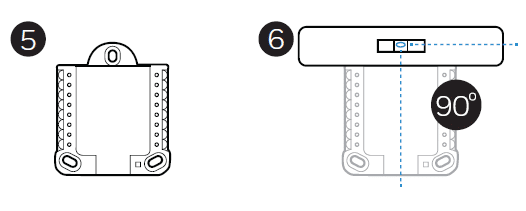
5. Before starting, turn the power off at the breaker box or switch. Open package to find the UWP. See Figure 5.
6. Position the UWP on the wall. Level and mark hole positions. See Figure 6. Drill holes at marked positions, and then lightly tap supplied wall anchors into the wall using a hammer.
‒‒ Drill 7/32” holes for drywall.
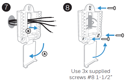
7. Pull the door open and insert the wires through the wiring hole of the UWP. See Figure 7.
8. Place the UWP over the wall anchors. Insert and tighten mounting screws supplied with the UWP. Do not overtighten. Tighten until the UWP no longer moves. Close the door. See Figure 8.
Power options
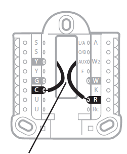
Insert R and C wires into designated terminals for primary AC power (C terminal is optional if batteries are installed, but it is recommended). Remove wires by depressing the terminal tabs.
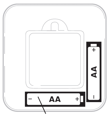
Insert AA batteries for primary or backup power.
Setting Slider Tabs
Set R Slider Tab.
- Use a built-in jumper (R Slider Tab) to differentiate between one or two transformer systems.
- If there is only one R wire, and it is connected to the R, Rc, or RH terminal, set the slider to the up position (1 wire).
- If there is one wire connected to the R terminal and one wire connected to the Rc terminal, set the slider to the down position (2 wires).
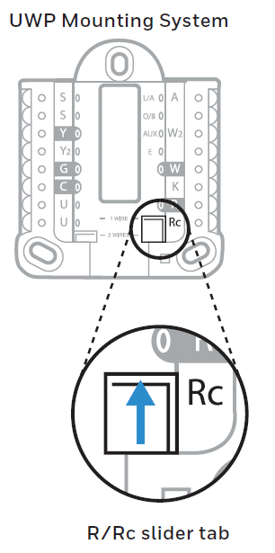
NOTE: Slider Tabs for U terminals should be left in place for T6 Pro models.
Wiring terminal designations
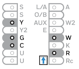
Note: Not all terminals may be used, depending on the system type that is being wired. The most commonly used terminals are shaded.
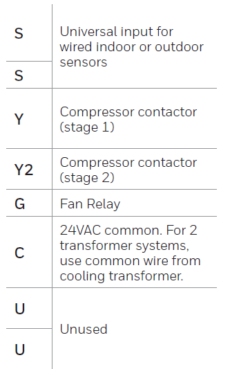
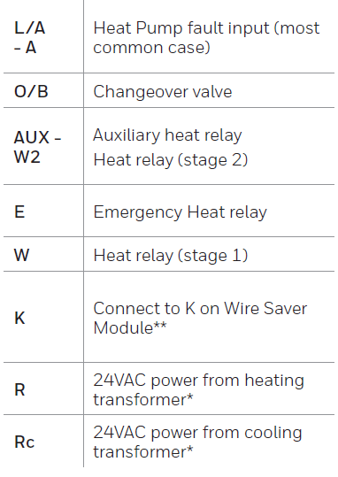
- The terminal can be jumped using Slider Tab. See “Setting Slider Tabs” above.
- The THP9045A1023 Wire Saver Module is used on heat/cool systems when you only have four wires at the thermostat, and you need a fifth wire for a common wire. Use the K terminal in place of the Y and G terminals on conventional or heat pump systems to provide control of the fan and the compressor through a single wire—the unused wire then becomes your common wire. See THP9045 instructions for more information.
Wiring conventional systems: forced air and Hydronics
Shaded areas below apply only to TH6320U/TH6220U or as otherwise noted.
1H/1C System (1 transformer)
R Power [1]
Rc [R+Rc joined by Slider Tab] [2]
Y Compressor contactor
C 24VAC common [3]
W Heat relay
G Fan relay
Heat-only System
R Power [1]
Rc [R+Rc joined by Slider Tab] [2]
C 24VAC common [3]
W Heat relay
Heat-only System (Series 20) [5]
R Series 20 valve terminal “R” [1]
Rc [R+Rc joined by Slider Tab] [2]
Y Series 20 valve terminal “W”
C 24VAC common [3]
W Series 20 valve terminal “B”
Heat-only System
(power open zone valve) [5]
R Power [1]
Rc [R+Rc joined by Slider Tab] [2]
W Valve
C 24VAC common [3]
1H/1C System (2 transformers)
R Power (heating transformer) [1]
Rc Power (cooling transformer) [1]
Y Compressor contactor
C 24VAC common [3, 4]
W Heat relay
G Fan relay
Heat-only System with Fan
R Power [1]
Rc [R+Rc joined by Slider Tab] [2]
C 24VAC common [3]
W Heat relay
G Fan relay
Cool-only System
R Power [1]
Rc [R+Rc joined by Slider Tab] [2]
Y Compressor contactor
C 24VAC common [3]
G Fan relay
2H/2C System (1 transformer) [6]
R Power [1]
Rc [R+Rc joined by Slider Tab] [2]
Y Compressor contactor (stage 1)
C 24VAC common [3]
W Heat relay (stage 1)
G Fan relay
W2 Heat relay (stage 2)
Y2 Compressor contactor (stage 2)
NOTES
Wire specifications: Use 18- to 22-gauge thermostat wire. A shielded cable is not required.
- Power supply. Provide disconnect means and overload protection as required.
- Move R-Slider Tab on UWP to the R setting. For more information, see “Setting Slider Tabs” on page 3
- Optional 24VAC common connection.
- The common connection must come from the cooling transformer.
- In ISU set Heat system type to Radiant Heat. Set the number of cool stages to 0.
- In Installer Setup, set system type to 2Heat/2Cool Conventional
Wiring heat pump systems
Shaded areas below apply only to TH6320U/TH6220U or as otherwise noted.
1H/1C Heat Pump System
R Power [1]
Rc [R+Rc joined by Slider Tab] [2]
Y Compressor contactor
C 24VAC common [3]
O/B Changeover valve [7]
G Fan relay
2H/1C Heat Pump System [8]
R Power [1]
Rc [R+Rc joined by Slider Tab] [2]
Y Compressor contactor
C 24VAC common [3]
O/B Changeover valve [7]
G Fan relay
Aux Auxiliary heat
E Emergency heat relay
L Heat pump fault input
2H/2C Heat Pump System [9]
R Power [1]
Rc [R+Rc joined by Slider Tab] [2]
Y Compressor contactor (stage 1)
C 24VAC common [3]
O/B Changeover valve [7]
G Fan relay
Y2 Compressor contactor (stage 2)
L Heat pump fault input
3H/2C Heat Pump System
(TH6320U only) [10]
R Power [1]
Rc [R+Rc joined by Slider Tab] [2]
Y Compressor contactor (stage 1)
C 24VAC common [3]
O/B Changeover valve [7]
G Fan relay
Aux Auxiliary heat
E Emergency heat relay
Y2 Compressor contactor (stage 2)
L Heat pump fault input
Dual Fuel System
R Power [1]
Rc [R+Rc joined by Slider Tab] [2]
Y Compressor contactor (stage 1)
C 24VAC common [3]
O/B Changeover valve [7]
G Fan relay
Aux Auxiliary heat
E Emergency heat relay
Y2 Compressor contactor (stage 2 – if needed)
L Heat pump fault input
S Outdoor sensor
S Outdoor sensor
Wire specifications: Use 18- to 22-gauge thermostat wire. A shielded cable is not required.
- Power supply. Provide disconnect means and overload protection as required.
- Move R-Slider Tab on UWP to the R setting. For more information, see “Setting Slider Tabs” on page 3
- Optional 24VAC common connection.
- In Installer Setup, set system type to 2Heat/2Cool Conventional.
- In Installer Setup, set the changeover valve to O (for cool changeover) or B (for heat changeover).
- In ISU set Heat system type to Heat pump. 1 compressor and 1 stage of backup heat.
- In ISU set Heat system type to Heat pump. 2 compressors and 0 stage of backup heat.
- In ISU set Heat system type to Heat pump. 2 compressors and 1 stage of backup heat.
