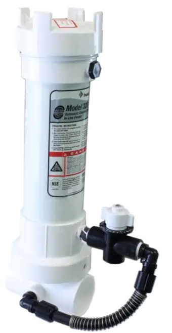
PENTAIR 320 Rainbow Chlorine Bromine Feeder

Information
It is important to read all information BEFORE proceeding with the installation. The information will guide you in installing your feeder properly and to avoid problems due to improper installation.
IF YOUR POOL OR SPA HAS COPPER PLUMBING . . . STOP!!
Never install the feeder into copper plumbing as pipe damage will occur. (See Equipment Safety CAUTION sheet enclosed). NOTE: If heaters are used, a Fireman’s Switch or equivalent must be installed to prevent possible damage and improper operation of Check Valve and other equipment subject to heat damage.
INSTALLATION INSTRUCTIONS MODEL #320
Note: Make sure all pumps and timer switches are in the OFF position.
WHERE TO INSTALL YOUR FEEDER
The #320 feeder is designed for permanent installation in the return line of your new pool or spa and must always be installed after the heater, pool cleaner, valves, etc. If your pool does not have a heater, then it must be installed after the filter or any other piece of equipment. DAMAGE TO THE HEATER AND OTHER EQUIPMENT COULD RESULT IF HIGHLY CHLORINATED
WATER FLOWS THROUGH IT.
If your pool is equipped with a solar system it may be necessary to install a HI FLOW KIT. This kit can be installed if your feeder is not getting adequate flow and/or pressure through the system. Refer to the information on sheet enclosed. Your feeder may be installed in existing PVC plumbing but will require a union and/or other fittings. The feeder comes complete for installation with 2″ or 1½” PVC plumbing. Choose a site in the return line where feeder can be installed in a vertical position. Always install as far from any metal equipment as practical since fumes, etc. can corrode them. If optional corrosion-resistant check valve is required refer to installation instructions before next step.
BASIC PLUMBING INSTALLATION INSTRUCTIONS
2″ OR 1½” PVC PIPE: If feeder is being installed on a pool, spa or pool/spa combination, correct plumbing procedures must be followed to insure proper flow through feeder. If pool or spa is plumbed with 2″ PVC pipe, be certain the pump, filter and heater all have 2″ inlet and outlet fittings. If any part of the equipment has less than 2″ fittings or pipe, then a minimum of 6″ x 1½” reducer bushings must be installed directly into the inlet side of the feeder using the 2″ x 1½” reducer bushings supplied. This will build pressure directly into the feeder insuring proper operation. Continue with 2″ PVC pipe on the outlet side of the feeder.
POOL/SPA COMBINATION:
If plumbing and equipment is a full 2″ and the feeder is being installed on the pool return line after the diverter valve, with a portion of the water diverted to the spa, install a minimum section of 6″ x 1½” PVC pipe directly into the inlet side of the feeder using the 2″ x 1½” reducer bushing supplied. Continue with 2″ PVC pipe on the outlet side of the feeder. This will compensate for that portion of water being diverted to the spa. 90° ELBOWS: Plumbing a 90° elbow directly into the inlet side of the feeder may cause turbulence inside the elbow. This will prevent water from being scooped into the feeder. A minimum of a 6″ length of PVC pipe should be installed between the 90° elbow and the inlet side of the feeder.
2″ PVC: Simply glue feeder to the return line using PVC SOLVENT CEMENT. Be sure arrows on feeder point in the direction of water flow returning to the pool or spa.
1½” PVC: Remove (2) 2″ x 1½” slip reducer bushings packed inside the feeder and glue into 2″ slip tee on bottom of feeder. Complete installation by gluing into 1½” return line making sure the arrows on feeder point in the direction of water flow returning to the pool or spa. Use only PVC SOLVENT CEMENT. Follow directions on solvent cement label. Allow to dry. Installation in now complete.
OPERATING INSTRUCTIONS
Before start up of feeder, your pool should be properly conditioned and the residual should be 1.0 to 1.5 ppm.The water in a newly-filled pool should be properly conditioned to insure maximum effectiveness of the feeder. Consult your local dealer for water conditioning information for your area.
- Remove cap of feeder and fill with proper size tablets.
For Pools: 1″ or 3″ dia. tablets For Spas: 1″ dia. tablets in optional Spa Chamber. - Make sure the O-ring is clean, lubricated with Lifegard Silicone and is in place, replace cap. Hand tighten only.
- Turn on the pump and timer switches for a minimum of 6 to 8 hours.
- Adjust control valve according to your pool/spa size. Use a test kit to determine the chemical residual. It is recommended that the chemical residual be checked daily for the first 5 days. Remember . . . hot days, higher water temperature or increased pool/spa activity will cause your pool/spa to use more sanitizer. When possible, increase the feed rate a day or two in advance. Because the chlorine demand in your pool/spa varies and is dependent on many factors (sunlight, bather load, water temperature, etc) your valve setting may have to be changed from time to time to adjust to these conditions. For example, the winter setting may be #2 while the summer setting is #3. Check the chlorine residual daily to find the ideal setting. Note: Higher numbers dispense more chemical. Small gradual changes are imperative for control.
HOW TO RECHARGE FEEDER
- Turn control valve to the closed position. SHUT OFF PUMP.
- Wait one minute. This will allow water and fumes to drain from feeder.
- Leave control valve closed and turn on pump. The check valve will prevent water from entering the feeder.
- Remove cap and fill with proper size tablets or sticks. (See Operating Instructions #1)
- Making sure O-ring is clean, lubricated with Lifegard silicone and is in place, replace cap. Hand tighten only.
- Open control valve to original setting. Inspect inlet line below control valve each time feeder is recharged. Replace lines yearly if necessary.
SPECIAL FEATURES AND INSTRUCTIONS
If while using 3″ diameter tablets the #320 feeder does not provide enough chlorine residual, switch to 1″ tablets. The smaller tablet will erode faster producing more chlorine residual. If this does not correct the situation, the #320 has been fitted with an optional opening at the top of the feeder (which is plugged). To accommodate attachment of the valve and tubing assembly for top entry of water into the feeder, an additional length of tubing has been included.The following procedure should only be used if the suggested change has not solved the situation. Top entry in normal situations can cause over-chlorination.
- Turn off pump and timer switches.
- Remove tubing by unscrewing the compression nut at each end of tubing.
- Remove plug at top of the feeder directly above control valve.
- Remove the control valve. If nipple stays in valve, carefully remove by using pliers at the center of nipple. There is no need to remove the 90° tube fittings.
- Wrapping with 2 or 3 wraps of threaded tape in the opposite direction of tightening. Screw into the opening where control valve was attached. Hand tighten plus 2 or 3 turns. Do not overtighten.
- Wrap threads of nipple with threaded tape.Thread nipple into top opening.Finger tighten only. Thread valve onto nipple. After nipple starts to turn from tightening valve, 2 to 3 more turns is enough. The nipple or valve can be broken by overtightening.
- Slide compression nut over long section of tube. Slide tube over tapered part of 90°tube fitting and tighten. Hand tighten only. Repeat for another end of tubing.
- Set control valve to #1. Turn on the pump and timers. Check residual daily to determine proper setting. Small gradual changes are imperative for control.
BELOW WATER LEVEL INSTALLATION
Feeder should be installed above water level whenever practical. If installed below water level, a drain valve must be installed to prevent spillage and dangerous splash back of high chlorinated water during recharging. Drill and tap a ¼” MPT hole at the same level the control valve is located. Make sure there is no water or tablets inside the feeder before drilling. Install optional drain valve, Part R172060, or suitable chemical resistant drain valve.
BELOW WATER LEVEL RECHARGING INSTRUCTIONS
- Shut off pump and timer switches.
- Shut off the control valve.
- Place a clean container under drain and open drain valve.
- Exercise extreme caution when opening or servicing feeder. Do not inhale fumes. Wear protective gear. Remove cap.Water will now drain from feeder. Empty container back into pool or spa.
- Close drain valve. fill with proper size tablets or sticks.
- Make sure the O-ring is clean, lubricated with Lifeguard Silicone and in in place, replace cap.
- Turn on pump and timer switches.
- Reset control valve to the original setting. Inspect inlet and outlet line each time feeder is recharged. Replace lines yearly if necessary.
D A N GER
READ CAREFULLY
This feeder is designed to use only CLEAN Trichlor-s-trizinetrione OR CLEAN Bromine tables – slow dissolving type. Never use dirty tablets. UNDER NO CIRCUMSTANCES MIX Trichlor or Bromine with Calcium Hypochlorite, with other forms of concentrated chlorine or with other chemicals. Keep inside of feeder clean of dirt and debris at all times. FIRE AND/OR EXPLOSION MAY RESULT. NEVER use oils or grease to lubricate o-ring. Oil in contact with Trichlor OR Bromine may result in FIRE. Lubricate o-ring with Lifegard Silicone o-ring Lubricant ONLY, available at your dealers. If shock treatments or Algaecides containing chemicals other than sanitizers tablets in feeder must be used, turn off Feeder OR remove tablets until the shock or Algae treatment is complete and all granules have dissolved. Failure to do so may result in granules mixing in feeder causing FIRE AND/OR EXPLOSION. The shock or algae treatment dissolved in water is safe with tablets. If you are not the original owner of this feeder, not sure which chemicals was used, or if dirt and/or debris inside feeder, be SAFE and flush thoroughly with fresh water. CAUTION SHOULD BE USED
WHEN REMOVING CAP. DO NOT INHALE FUMES.
CALCIUM HYPOCHLORITE IS NOT TO BE USED IN ANY FORM. Use of chemicals other than listed by the manufacturer may be hazardous.
Bromine Standpipe Installation
To increase erosion of small bromine tablets, install Bromine Standpipe as follows:
- Remove screen from bottom of chamber exposing check valve (F)
- Insert adapter (T) into check valve opening.
- Cut supplied 5/8″ black tube (Q) to 6″ length and push tube into adapter opening.
YOU MAY SUBSTITUTE BROMINE TABLETS OR STICKS FOR TRICHLOR IN THIS FEEDER. DO NOT MIX.
CALCIUM HYPOCHLORITE IS NOT TO BE USED IN ANY FORM.
IMPORTANT OPTION.
SEE CORROSION CAUTION SHEET.
CAUTION
Do not install feeder into copper plumbing. Pipe damage could occur. Never install feeder before heater. Heater damage could occur.
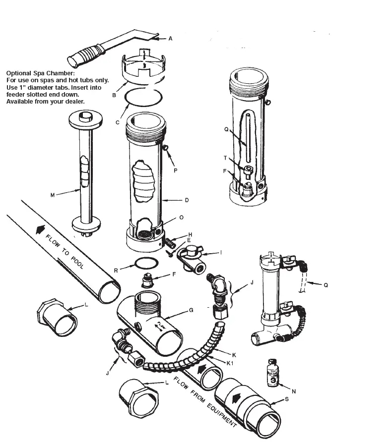
#320 CHLORINE / BROMINE FEEDER PARTS BREAK DOWN DRAWING
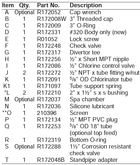
*Not used with 2″ PVC, for 1½” PVC only.
**Be sure screen has not come loose in shipment—if loose: Simply snap over 4 posts in bottom of chlorinator to replace.
NOTE: To service check valve F, Remove lockscrew E, and unscrew (counter-clockwise) D chlorinator body from G divertor tee. 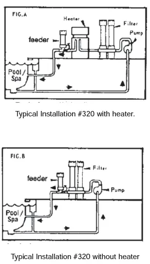
DIRECTIONS
- Turn off pump and timer switches.
- Loosen compression nut and remove Feeder tube and 90° elbow from the diverter tee at base of Feeder.
- Using thread seal tape as thread sealant, wrap ½” MPT plug threads (1) with several turns of the tape only.
Install in place of 90° elbow on diverter tee. - Disconnect another end of Feeder tube from control valve 90° elbow, by loosening the compression nut. Use the compression nuts from old tube to attach new 6′ section (2).
- Push compression nut over tubing end, then push tubing onto tapered end of elbow. Tighten nut firmly by hand.
- Connect another end of plumbing. IF THE POOL/SPA HAS A HEATER, INSTALL IT BETWEEN FILTER AND HEATER. IF YOUR POOL/SPA HAS A SOLAR SYSTEM, INSTALL IT BEFORE SOLAR
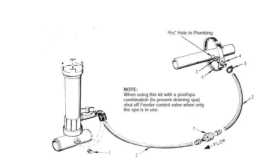
SYSTEM INLET LINE. IF NO HEATER, INSTALL IT BETWEEN PUMP AND FILTER. Drill 9/16″ hole in plumbing, remove burrs, and install saddle clamp assembly. (See illustration) Tighten the clamp with a screwdriver. Slide small stainless steel clamp #3 over tubing #2 and slide tubing over saddle tube fitting #4. Secure tubing to fitting by tightening camp with screwdriver. Make sure clamp is below rib at end of saddle tube fitting. - To install ½” CHECK VALVE, cut tube approximately 6″ away from plumbing connection. Remove compression nuts from check valve. Slide nuts over both ends of tube. Insert check valve ends into both pieces of tubing and tighten compression nuts firmly by hand. Be sure arrow “FLOW” is pointing toward the Feeder.
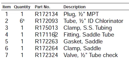
HI FLO FEEDER KIT #R171099 PARTS BREAKDOWN DRAWING
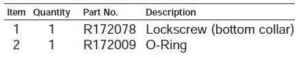
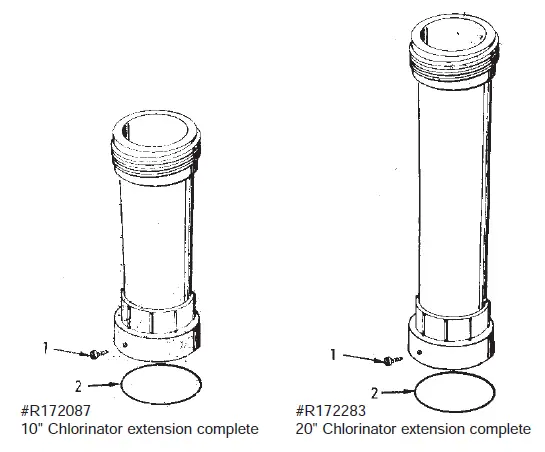
EXTENS IONS
- Going on vacation?
- Need more chlorine?
- Filling Chlorinator/Brominator too frequently?
LIFEGARD CHLORINATOR EXTENSIONS SOLVE THE ABOVE PROBLEMS BY:
- Increasing tablet capacity.
- Larger chamber size allows more erosion of tablets. (See special instructions below)
The 10″ extension doubles and the 20″ extension triples (approximately) the capacity and time between refills. *AVAILABLE THROUGH LIFEGARD DEALERS ONLY.
NOTE: On free standing #300 series chlorinators, the base of the chlorinator should be secured to
prevent the possibility of the chlorinator tipping over due to increased height.
INSTALLATION INSTRUCTIONS
- Follow recharging instructions to the point of filling with tablets
- Making sure O-Ring is clean, lubricated with Lifegard Silicone and in place, screw on extension tightly and secure with lock screw. (You may wish to wait until back in operation before tightening screw to insure against leaks).
- Fill with tablets and continue with normal recharging procedure.
SPECIAL INSTRUCTIONS:
The large chamber size will result in more chlorine being dispensed at the same valve setting, therefore, once installed, several days monitoring will be necessary to readjust chlorinator output.
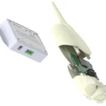
R 172288 1½ ” and 2 ” SLIP SPRING CHECK VALVE
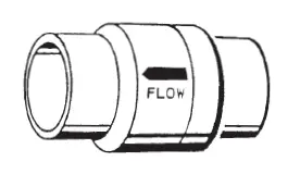
- Special corrosion resistant 1½” & 2″ slip spring check valve can be used
- to check back flow of fluids, air, etc.
- Full free flow design
- Special Spring and Seal for corrosive applications.
- Enclosed spring insuring free operation.
- Very effective when used in conjunction with chlorinator to check back flow
- of chemicals to pool/spa equipment, preventing corrosion problems
- and damage.
- Can be mounted in any position.
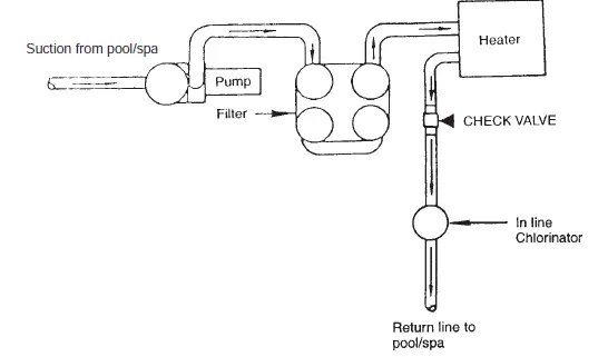
Typical check valve installation
NOTE: If heaters are used, a Fireman’s Switch or other safety device must be installed to prevent possible damage and improper operation of Check Valve and other equipment subject to heat damage.
EQUIPMENT SAFETY CAUTION!
PLEASE READ CAREFULLY
Since most pool’s plumbing is not airtight, and a mixture of air and chlorine is highly corrosive to metals, it is important to protect these items from corrosion in the OFF period when no circulation is taking place. (There is no chance for chlorine corrosion when the circulating system is in operation.)
Of course, corrosion or erosion of metal components can still occur independently of any chlorinator installation for the following reasons:
- Water velocity too high.
- Water pH less than 7.2.
- Total alkalinity less than 100 PPM.
If your pool or spa has any of the following equipment, special plumbing procedures must be followed for safe operation:
- Brass or bronze gate, rotary or backwash valves.
- The preceding valves are constructed of PVC or other plastic material with metallic shafts.
- Filters, heaters, heat exchanges or other items with metallic tanks, shafts, coils or tubes.
- NOT FOR USE IN COPPER PLUMBING.
Installation of the OPTIONAL Rainbow #R172288 positive seal, corrosion resistant check valve SHOWN ON REVERSE SIDE will prevent the backflow of corrosive liquids and gases that can damage equipment containing metallic components. Examples listed above.
WARNING: If your pool is equipped with a permanent built in pool-cleaning system, damage could occur to that system if materials are not compatible with low pH Tri-Chloro feeders. Check with the manufacturer for compatibility.
WARNING: Before installing this product, read and follow all warning notices and instructions accompanying this valve. Failure to follow safety warning and instructions can result in severe injury, death, or property damage. Call (800) 831-7133 for additional free copies of these instructions.
IMPORTANT NOTICE!
Attention Installer: This manual contains important information about the installation, operation and safe use of this product. This information should be given to the owner/operator of this equipment.
- The valve must be installed by a qualified serviceman in accordance with the National Electrical Code and all applicable local codes and ordinances.
- Always disconnect power to the equipment at the circuit breaker before servicing any of the equipment. Ensure that the disconnected circuit is locked out or properly tagged so that it cannot be switched on while you are working on the equipment. to do so could result in serious injury or death to servicemen, operator users or others due to electric shock.
- Position the filter and the air relief valve to safely direct water drainage and purged air or water. Water discharged from an improperly positioned filter or valve can create an electrical hazard that can cause severe personal injury as well as damage to property.
For Installation of Electrical Controls at Equipment Pad (ON/OFF Switches, Timers and Automation Load Center)
Install all electrical controls at equipment pad, such as on/off switches, timers, and control systems, etc. to allow the operation (startup, shut-down, or servicing) of any pump or filter so the user does not place any portion of his/her body over or near the pump strainer lid, filter lid or valve closures. This installation should allow the user enough space to stand clear of the filter and pump during system start-up, shut down or servicing of the system filter.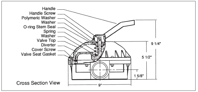
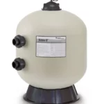
FILTER OPERATES UNDER HIGH PRESSURE.
When any part of the circulating system, (e.g., clamp, pump, filter, valve(s), etc.), is serviced, air can enter the system and become pressurized. Pressurized air can cause the lid to separate which can result in severe injury, death, or property damage. To avoid this potential hazard, follow these instructions:
- Before repositioning valve(s) and before beginning the assembly, disassembly, or adjustment of
the clamp or any other service of the circulating system: (A) Turn the pump OFF and shut OFF any automatic controls to ensure the system is NOT inadvertently started during the servicing; (B) open the manual air relief valve; (C) wait until all pressure is relieved. - Whenever installing the filter clamp FOLLOW THE FILTER CLAMP INSTALLATION INSTRUCTIONS EXACTLY.
- Once service on the circulating system is complete FOLLOW SYSTEM RESTART INSTRUCTIONS EXACTLY.
- Maintain circulation system properly. Replace worn or damaged parts immediately, [e.g., clamp, pressure gauge, valve(s), o-rings, etc].
- Be sure that the filter is properly mounted and positioned according to the instructions provided.
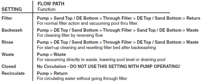
Valve Positions Overview
Valve Installation
This valve is available in two models for use with sand type or diatomaceous earth (DE) type pool filters. Be sure that you have the correct model for your filter. Installing the incorrect model may cause your pump to dead head, or drain the pool when in backwash position.
- Confirm correct valve is being used; DE valves for DE filters and Sand valves for Sand filters.
- Install valve to filter by securing bulkhead nuts on valve to fittings on the filter.
- Plumb pump piping to center pipe in valve.
- Plumb return and waste lines.
Technical Data
Replacement Parts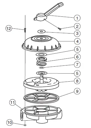
| Item | P/N | Description | Qty. |
| 1 | 272520 | Handle | 1 |
| 2 | 272405 | Screw – Handle | 1 |
| 3 | 272402 | Washer, Plastic | 1 |
| 4 | 272412 | Valve Top | 1 |
| 5 | 271193 | Washer – 18 GA | 2 |
| 6 | 272400 | Spring – Compression | 1 |
| 7 | 272406 | O-ring – Diverter | 1 |
| 8 | 272413Z | Diverter | 1 |
| 9 | 272409 | Seal -Diverter | 1 |
| 10 | 98211400 | Nut – 1/4″ – 20 Hex | 8 |
| 11 | 272415 | Plat – 2″ Valve Bottom | 1 |
| 12 | 272403 | Screw – 1/4″ – 20 | 8 |
| * | 272422 | Valve Top Assembly | 1 |
*This part number includes items 1 thru 9
Note: When replacing gasket P/N 272409, secure it to valve bottom with an instant cyanocrylate adhesive suitable for bonding rubber to plastic.
Head Loss Curves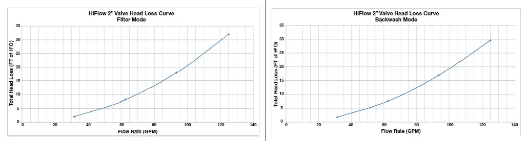
1620 HAWKINS AVE., SANFORD, NC 27330 • (919) 566-8000
10951 WEST LOS ANGELES AVE., MOORPARK, CA 93021 • (805) 553-5000
WWW.PENTAIR.COM
All Pentair trademarks and logos are owned by Pentair or one of its global affiliates. Hi-Flow™ is a trademark of Pentair Water Pool and Spa, Inc. and/or its affiliated companies in the United States and/ or other countries. Unless expressly noted, names and brands of third parties that may be used in this document are not used to indicate an affiliation or endorsement between the owners of these names and brands and Pentair Water Pool and Spa, Inc. Those names and brands may be the trademarks or registered trademarks of those third parties. Because we are continuously improving our products and services, Pentair reserves the right to change specifications without prior notice. Pentair is an equal opportunity employer.
© 2018 Pentair Water Pool and Spa, Inc. All rights reserved. This document is subject to change without notice.