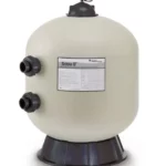
OMNIFILTER Quickconnect Tankless Reverse Osmosis System
Product Information
The OMNIFILTER QuickConnect Water Filtration System is a
tankless reverse osmosis system designed to provide clean and
purified water. This system is manufactured by Pentair, a trusted
brand in water filtration technology.
Before installing the tankless reverse osmosis system, it is
important to ensure that your water supply meets the following
operating specifications:
- Recommended Feed Pressure Range: [Insert recommended feed
pressure range] - Production Rate (GPD): [Insert production rate]
- Pressure Range: [Insert pressure range]
- Temperature Range: [Insert temperature range]
- Operating Voltage: [Insert operating voltage]
- TDS (Total Dissolved Solids): [Insert maximum TDS]
- Maximum Hardness: [Insert maximum hardness level]
- Sulfide, Iron, and Manganese: [Insert tolerance for sulfide,
iron, and manganese] - Chlorine in Water Supply: [Insert tolerance for chlorine
presence] - pH Limits: [Insert pH limits]
- Overall Dimensions: [Insert dimensions of the system]
- Weight: [Insert weight of the system]
Please note that failure to comply with these operating
specifications may reduce the effectiveness of the system and void
the warranty.
Product Usage Instructions
- Ensure that your water supply meets the operating
specifications mentioned above. - Select an appropriate location for installing the OMNIFILTER
QuickConnect Water Filtration System. It should be near a cold
water supply line and a drain for wastewater. - Shut off the main water supply to your home or building.
- Install the pre-filter cartridge(s) according to the provided
instructions. This step may vary depending on the specific model of
the system. - Connect the system’s inlet valve to the cold water supply line
using the provided fittings. Ensure a secure and leak-free
connection. - Connect the system’s outlet valve to a faucet or dispenser
using the provided fittings. Again, ensure a secure
connection. - Connect the wastewater drain line to a suitable drain. Make
sure it is positioned to prevent any backflow or leaks. - Turn on the main water supply and check for any leaks. If leaks
are detected, immediately shut off the water supply and fix them
before proceeding. - Allow the system to flush for a few minutes to remove any air
or impurities. - Follow the system-specific instructions for turning on and
operating the reverse osmosis filtration process. - Regularly replace the filter cartridges as recommended by the
manufacturer to ensure optimal performance and water quality.
For more detailed installation and operation instructions, refer
to the OMNIFILTER QuickConnect Water Filtration System Tankless
Reverse Osmosis System Installation and Operation Manual provided
by Pentair.
Remember to consult a professional plumber or contact the
manufacturer’s customer support if you encounter any difficulties
during installation or have any questions regarding the product
usage.
View Fullscreen
OMNIFILTER
QUICKCONNECT WATER FILTRATION SYSTEM TANKLESS REVERSE OSMOSIS SYSTEM INSTALLATION AND OPERATION MANUAL
©2022 Pentair Residential Filtration, LLC
pentair.com
IMPORTANT: Before installing this tankless reverse osmosis system, make certain your water supply complies with the following operating specifications. Failure to do so may reduce the effectiveness of the system and will void the warranty.
· Please read all instructions and precautions before installing and using your Tankless Reverse Osmosis system.
· For standard, under-sink installation on 3/8″ (9.52 mm) steel, brass, or copper cold water line.
· When selecting a location of the system, take into consideration the length of tubing required for connections between existing plumbing and system components. Some installation sites may require more tubing than provided in the kit.
· Ensure that the system’s installation location is within 5 feet (1.52 meters) of a 110 volt grounded outlet.
· Numbered diagrams correspond with numbered steps.
SPECIFICATIONS
Recommended Feed Pressure Range: Production Rate (GPD): Pressure Range: Temperature Range: Operating Voltage:
TDS: Maximum Hardness: Sulfide, Iron and Manganese: Chlorine in Water Supply: pH Limits: Overall Dimensions:
Weight:
10 to 60 psi (0.694.14 bar) 396.4 gpd (1500 Lpd) 15 to 100 psi (2.756.89 bar) 40100°F (4.437.8°C) Input Voltage: 100-240V AC Output Voltage: 24V DC <2000 ppm <10 gpg (170 mg/L) <0.01 ppm <2 ppm 311 5.51″ W x 17.60″ D x 17.10″ H (140mm x 447mm x 434mm) 25.35 lbs (11.5 kg)
If the hardness of your water is above 10 gpg (171 mg/L), lime scale will build up rapidly on the membrane. Scale buildup will plug the membrane and make the system ineffective. We do not recommend these tankless reverse osmosis systems be used with water in excess of 10 gpg (171 mg/L) hardness.
A maximum total level of approximately 0.01 ppm sulfide, iron or manganese is permissible. See your local dealer to reduce these substances in your water.
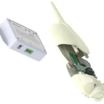
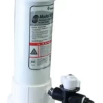
PARTS INCLUDED:
· Main Body Assembly · Power Adapter · Composite Filter (CF) & Carbon Filter (CB) Cartridges · RO Membrane Cartridge (RO) · Inlet Water Adapter · Smart Faucet · 1/4″ Tubing – White · 1/4″ Tubing – Red · 3/8″ Tubing – White · 1/4″ Quick Connect Locking Clip · 3/8″ Quick Connect Locking Clip · 1/4″ Quick Connect Fitting · Drain Line Clamp · Front Cover · Owner’s Manual · Quick Reference Guide
Tools and Materials Required
· Hand or electric drill (cordless preferred) · (2) Adjustable wrenches · Slotted and Phillips screwdrivers · File · Safety glasses · Drill bits: 1/8″, 3/16″, 1/4″, 3/8″ · Tube cutter or utility knife · Pencil · Towel · Bucket If sink does not have hole for separate faucet: · Center punch · 3/4″ hole saw or drill bit · Safety mask
NOTE: All tools may not be necessary for installation. Read installation procedures before starting to determine what tools are necessary.
CALIFORNIA PROPOSITION 65 WARNING
WARNING: This product contains chemicals known to the State of California to cause cancer or birth defects or other reproductive harm.
PRECAUTIONS
GENERAL
WARNING: Do not use with water that is microbiologically unsafe or of unknown quality without adequate disinfection before or after the system.
CAUTION RO System must be protected against freezing,
which can cause cracking of the RO components and water leakage. NOTE:
· Your water must be within required limits for satisfactory operation. If not, your membrane life may be shortened and your warranty will be voided (see Specifications on page 2).
· This tankless reverse osmosis system will not protect against disease-causing bacteria or remove naturallyoccurring harmless bacteria.
· Install on cold water line only. · Make certain that installation complies with all state and
local laws and regulations. · The replacement cartridges and tankless reverse osmosis
element included with this system have limited service lives. Changes in taste, odor, and color of the water being filtered indicate that the cartridge should be replaced. · After prolonged periods of non-use (such as during a vacation) it is recommended that the system be flushed for 5 minutes before it is used. · A drinking water cartridge may contain carbon fines (very fine black powder). After installation, flush the system for 5 minutes to remove the carbon fines before using the water. · It is recommended that you run the tap at least 20 seconds prior to using water for drinking or cooking purposes. · The contaminants or other substances removed or reduced by this water treatment device are not necessarily present in your water.
2 · QUICKCONNECT TANKLESS RO Installation and Operation Manual
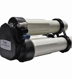
HOW REVERSE OSMOSIS WORKS
The Tankless Reverse Osmosis (RO) System uses a semipermeable membrane to reduce dissolved salts and minerals, improving the taste and odor of your water. The RO membrane is made of layers of micron-thin film wound around a hollow center core. Water molecules can pass through the membrane, but dissolved salts and minerals are rejected.
The Tankless Reverse Osmosis System features 3-stage filter action. Your water supply is pre-filtered to reduce dirt and chlorine that may foul the membrane. The RO membrane separates this pre-filtered water into PRODUCT WATER and DRAIN or REJECT WATER. Incoming water pressure forces the product water through the membrane. Dissolved solids and other contaminants cannot pass through the membrane and are sent to the drain as reject water.
For each gallon of water produced, less than 1 gallon of water goes to the drain. When used under the Specifications on page 2 of the manual, your Tankless Reverse Osmosis membranes should last 12-24 months.
INSTALLATION
GROUNDING INSTRUCTIONS: This appliance must be grounded. In the event of a malfunction or breakdown, grounding will reduce the risk of electric shock by providing a path of least resistance for electric current. This appliance is equipped with a cord having an appliance-grounding conductor and a grounding plug. The plug must be plugged into an appropriate outlet that is installed and grounded in accordance with all local codes and ordinances.
WARNING: Improper connection of the appliancegrounding conductor can result in a risk of electric shock. Check with a qualified electrician or service representative if you are in doubt whether the appliance is properly grounded. Do not modify the plug provided with the appliance; if it will not fit the outlet, have a proper outlet installed by a qualified technician.
A. The power-supply receptacle for the appliance shall be installed in a cabinet or on a wall adjacent to the undercounter space in which the appliance is to be installed;
B. There shall be an opening through the partition between the compartments specified in (A) that is large enough for the attachment plug to pass through. The longest dimension of the opening shall not be more than 1-1/2 in (38 mm);
C. The edges of the opening specified in (B) shall, if the partition is wood, be smooth and rounded, or, if the partition is metal, be covered with an edge protector provided for this purpose by the manufacturer; and
D. Care shall be exercised, when the appliance is installed or removed, to reduce the likelihood of damage to the supply cord.
QUICKCONNECT TANKLESS RO Installation and Operation Manual · 3
INSTALLATION CONTINUED . . .
1. Installing the Water Supply Adapter
1
The supply adapter fits 1/2″-14 NPS supply threads or 3/8″ x 3/8″ compression. If local codes permit, it may be used to connect the system to the cold water supply line. If local codes do not permit the use of the supply adapter, alternate connectors can be obtained from your local supplier.
Directions:
(A) Turn off cold water supply line. If cold water line does not have a shut-off valve under the sink, you should install one.
(B) Turn on the cold water faucet and allow all water to drain from line.
(C) Disconnect riser cold water supply valve.
(D) Ensure the sealing gasket is fully seated into the feed adapter valve female thread.
(E) Install feed adapter valve onto supply valve as desired. The feed adapter valve may be installed at the bottom of the supply hose or the top of the cold water line. Hand tighten only.
(F) Connect the riser to the feed adapter valve.
NOTE: Be careful not to cross-thread.
2. Selecting the Faucet Location
The drinking water faucet should be positioned with function, convenience, and appearance in mind. An adequate flat area is required to allow faucet base to rest securely. The faucet fits through a 3/4″ hole. Most sinks have pre-drilled 1-3/8″ or 1-1/2″ diameter holes that may be used for faucet installation. If these pre-drilled holes cannot be used or are in an inconvenient location, it will be necessary to
drill a 3/4″ hole in the sink to accommodate the faucet.
CAUTION This procedure may generate dusts which can cause severe irritation if
inhaled or come in contact with the eyes. The use of safety glasses and safety mask for this procedure is recommended.
CAUTION DO NOT ATTEMPT TO DRILL THROUGH AN ALL-PORCELAIN SINK. If
you have an all-porcelain sink, mount the faucet in pre-drilled sprayer hole or drill through countertop next to sink.
CAUTION When drilling through a countertop, make sure the area below the
drilled area is free of wiring and piping. Make certain that you have ample room to make the proper connections to the bottom of the faucet.
CAUTION Do not drill through a countertop that is more than 1″ thick.
CAUTION Do not attempt to drill through a tiled, marble, granite or similar
countertop. Consult a plumber or the countertop manufacturer for advice or assistance.
The following instructions apply to stainless steel sinks ONLY.
(A) Line bottom of sink with newspaper to prevent shavings, parts or tools from falling down the drain.
(B) Place masking tape over the area to be drilled to help prevent scratches if drill bit slips.
(C) Mark point with center punch. Use a 1/4″ drill bit to drill a pilot hole through sink.
(D) Use a 1-1/4″ hole saw to enlarge hole. Smooth rough edges with a file.
2
4 · QUICKCONNECT TANKLESS RO Installation and Operation Manual
Pilot Hole
B
C D
1/41″/4″C
11/4″ 11/4″
D
Mounting A
Hole
INSTALLATION CONTINUED . . .
3
3. Mounting the Faucet
NOTE: Not all parts provided with the faucet may be needed for installation.
(A) Slide chrome plate and black rubber washer onto faucet by threading both drain tubes through the holes on the plate and washer.
(B) Attach large diameter white 1/4″ drain tube to barb fitting at the faucet base.
(C) Slide white extension spacer onto long threaded section of faucet. Open end of extension should come in contact with base of faucet.
(D) Screw washer, and locking nut onto end of faucet threads.
(E) Screw quick connector onto end of faucet threads.
(F) Wet end of 1/4″ white tube. Push into bottom of quick connector. Tug gently to be sure connection is complete. Insert 1/4″ quick coupling lock plate between quick connect port and claw of tubing.
NOTE: To remove the tube, push on the fittings’ collar and pull the tube out.
(G) Holding the faucet, feed the tube through the hole in the sink. Position the faucet handle at a desired location.
(H) Center the faucet. Tighten the locking nut with a wrench until it is tight.
4. Installing the Drain Clamp
NOTE: If you have a single-basin sink with a disposal unit, call Technical Support
5
for options.
NOTE: Before installing the drain clamp, check the drainpipes under the sink
B
for corrosion. Corroded pipes should be replaced before continuing with
installation.
(A) Attach the drain clamp to a vertical section of the drainpipe, about 6″ above the trap. Make sure the opening on the drain clamp is facing towards the drinking water faucet.
(B) Using the fitting hole of the drain clamp as a guide, drill a 1/4″ hole through one side of the drainpipe.
(C) Remove the drain clamp from the drainpipe and enlarge the hole with a 3/8″ drill bit. Use a file to remove rough edges from the drilled hole.
5
(D) Make sure the black rubber gasket is adhered to the inside of the drain clamp and place the drain clamp assembly over the drilled hole. Look through the hole and position the clamp so that the center of the clamp hole is slightly higher (about 1/16″) than the center of the drilled hole. Tighten the clamp securely.
(E) Screw the plastic compression nut onto the drain clamp until hand-tight.
5. Connecting the System to the Drain
CAUTION This is a gravity drain line. Any loops, kinks or sharp bends must be
eliminated before proceeding.
(A) Locate the 1/4″ red tubing.
(B) Insert one end of the tubing into the “Drain” port on the back of the system. Insert 1/4″ quick coupling lock plate between the quick coupling and the jack
6
catch of the tubing.
(C) Run the other end of the tubing to the desired drain location.
6. Installing the System
WARNING: When selecting a installation location of the system, take into consideration the length of tubing required for connection between components. Some installation sites may require more tubing than provided in the kit.
(A) Select a location under the sink, or other suitable area where the system will be installed.
NOTE: The system carton can be used to determine the operational footprint required for installation of the system and replacement cartridges.
(Figure 6) Carton is oversized 4-6″ in each direction for packing materials.
(B) The system should be set on a firm, solid surface that is able to support the weight of the system.
Faucet Body Upper Gasket Countertop Gasket Ring Below Gasket Installation Knob Inlet Water Threaded Pipe Direct Quick Coupling 1/4″ Quick Coupling Lock Plate 1/4″ PE Pipe
3/8″ Tube
C
QUICKCONNECT TANKLESS RO Installation and Operation Manual · 5
7
INSTALLATION CONTINUED . . .
7. Connecting the Faucet to the System
(A) Determine the length of plastic white tubing needed to connect from the system to the faucet. Be sure to allow enough tubing to prevent kinking and cut the tubing squarely. Use a marker to mark one end of the tubing 5/8″ from the end. Wet the end of the 1/4″ tube and push into the port on the back of the system labeled “Drinking Faucet”. Insert 1/4″ quick coupling lock plate between quick connect port and claw of tubing.
CAUTION Do not bend or crimp tube while inserting.
(B) Gently pull back on the tube to ensure it is connected properly.
8. Connecting the System to the Water Supply Adapter
(A) Locate remaining length of 3/8″ plastic white tubing.
8
(B) Place a mark on the tubing 5/8″ from the end. Moisten the end of the tubing
with water and insert with a twisting motion push into inlet quick connect
fitting on the back of the system labeled “Inlet”. Insert the 3/8″ quick
coupling lock plate between the quick connect port and the claw of the water
inlet tubing.
(C) Cut the tube to a length that will allow connection to the Water Supply Adapter that was installed in Step 1. Ensure the tubing does not kink. Place the Compression Nut and Compression Sleeve over the Plastic tubing and then place the Insert Fitting into the end of the Tubing. Tighten the Compression Nut onto the Water Supply Adapter.
9. Connecting the Power Adapter
(A) Locate the electrical adapter, and plug the smaller end into the power receptacle on the back of the system.
9
(B) Locate the Faucet power cord and plug into the port titled “Faucet Power” on the back of the system. Screw the movable nut on the aviation connector clockwise until tightened.
10. Filter Installation
(A) Remove filter cartridges from their packaging and remove the rubber stoppers at the top of each cartridge.
(B) The order sequence of the cartridges is as follows: Top: RO Membrane Cartridge Middle: CB Filter Cartridge Bottom: CF Filter Cartridge
(C) Insert filter cartridges with handle parallel to the floor, turn 90° so that the handle is now perpendicular to the floor.
11. System Start-up
10
(A) Connect machine to power supply and plug into electrical outlet. When the machine is first powered on, a small beep will occur and four indicator lights will flash.
(B) The machine will automatically flush for 5 minutes. During this time the water quality indicator light will flash red.
(C) Open faucet and allow to run for 30 minutes. During this time the water quality indicator light will flash with the actual water quality color.
(D) While flushing occurs, check the tightness of all parts and fittings carefully to ensure no leaks at the connection points.
(E) Once flushing is complete, the faucet can now be closed. The machine will enter a normal water production state and the water indicator light will remain on with the actual water quality color.
CAUTION Visually check the entire system for leaks. If a leak is present, see
Troubleshooting on page 8.
NOTE: To complete 24-hour flushing, reference page 9. Flush 24-hours upon start or before first use. For the first 24-hours use water for cooking and/or cleaning.
6 · QUICKCONNECT TANKLESS RO Installation and Operation Manual
Filter Cartridge Replacement
NOTE: The life of the filter cartridges depends on water volume used and the quality of the feed water. It is recommended that the filter cartridges be replaced every 12 months, or when there is a noticeable change in taste, odor, or flow of filtered water.
Ensure the correct cartridge is purchased for the system. Pentair Tankless RO System #4006877 uses the following replacements: #4006882 / ROM-24M / Replacement RO Membrane #4006943 / CF-12M / CB-12M / Replacement Filter 2-Pack
Cartridge Sequence
Cartridge Replacement A. Twist cartridge 90 degrees counter-clockwise and remove
from system. B. Install new cartridge in the proper location, push firmly and
twist clockwise.
Indicator Lights
Indicator Lights · CF: CF Filter Cartridge Lifetime Indicator · RO: RO Membrane Cartridge Lifetime Indicator · CB: CB Filter Cartridge Lifetime Indicator · Water Drop: Water Quality Indicator (TDS indicator)
Smart Faucet Indicator Lights
· To quickly and easily get filter life indication, the Smart Faucet includes an LED ring around the base of the faucet which indicates filter life.
· Blue – Normal, filter life is good · Purple – Needs attention, filter life will expire soon.
Indicator will change when there are 15 days of filter life remaining. · Red – Expired, filter should be changed
Inserting Cartridges into System
Cartridges Fully Engaged in System
Troubleshooting
QUICKCONNECT TANKLESS RO Installation and Operation Manual · 7
Indicator Status
System Error Indications
Error Type Timeout fault
Indicator Lights 3 red indicators flash
Frequent start-stop Water leakage
Low temperature
3 purple indicators flash 4 red indicators flash 3 indicators flash
Filter Cartridge Lifetime Display
Fault Indicator Go out Go out
Red indicators flash Red indicators flash
Recover Method
Power off and then power back on the system
Power off and then power back on the system
Locate and repair water leak
Power off and then power back on the system
Lifetime status
Life Time Left (Days)
Treatment Capacity Remaining
Warning Type
Filter cartridge indicator
Buzzer
Normal Early Warning
Alarming
Greater than 15 days
Greater than 0 and less than 15 days
Zero days
Greater than 150 liters
Continuous Blue light on
No warning reminder
Greater than 0 and less than 15 liters
Zero
Continuous Purple light on Continuous Red light on
Beeps twice during water production (beep 0.3
seconds, stop 1 second)
Beeps during production (beep 0.3 seconds, stop 1
second)
Water Quality Indicator Display
Blue < 100 ppm
TDS LED Color Purple > 100 < 150 ppm
Red > 150 ppm
8 · QUICKCONNECT TANKLESS RO Installation and Operation Manual
Machine Functions
Function
Action logic
Filter Cartridge Indicator
Initial system power on
Beeps 0.1 second, indicator display 3 seconds
Blue-Purple-Red indicator light
First time use washing
Replacement filter flushing
Automatic flushing 5 mins
User turns on the faucet, allows water to flush for 24 hours
NOTE: View To Complete 24-hour Flushing section on the bottom of page 9.
1. CF filter cartridge: turn on the faucet and flush for 5 minutes.
2. RO filter cartridge: turn on the faucet and flush for 30 minutes.
3. CB filter cartridge: turn on the faucet and flush for 15 minutes.
4. Reset the RO filter cartridge together with other filter cartridge: turn on the faucet and flush for 5 minutes, then re-flush for 30 minutes.
5. Reset the CF filter cartridge and CB filter cartridge: turn on the faucet and flush for 15 minutes.
Water production
Water making action
Standby
The machine stops making water and goes into standby mode
Blue light always on
Blue light always on
Light always on (base on filter lifetime
display) Light always on (base on filter lifetime
display)
Fault Indicator Blue-Purple-Red
indicator light Red flashing Flashing according to current water quality status
Water quality indicator light red flashing during
flushing
Light always on according to current
water quality Go out
To reset the filter cartridge: Press and hold the corresponding filter cartridge reset key for 5 seconds. A small beep will sound, the corresponding filter cartridge life indicator will flash purple twice and then turn blue.
To Complete 24-Hour Flushing
A. Within 10 seconds of plugging the system in, press the CF filter button 5 times. You will hear 2 beeps.
NOTE: If the system is already plugged in, unplug the system first and plug it back in to complete this step.
B. Open the faucet and allow water to run for 24-hours. C. Close the faucet. D. Unplug the system and plug it back it. Within 10 seconds
of plugging the system in, press the CF filter button 5 time. You will hear 1 long beep for 3 seconds. E. The system is ready for operation.
QUICKCONNECT TANKLESS RO Installation and Operation Manual · 9
Leaks from tubing fittings
1. Relieve pressure by turning off the water supply to the system and opening faucet until water flow stops. Place a bucket or towel under the system to catch any water drips.
2. Depress collet on system or inlet supply adapter tubing fittings and pull tubing from fitting. Inspect surface of tubing for scratches or debris. Clean or cut back tubing to access clean surface.
3. Wet the end of the inlet tubing and press into the inlet fitting of the system. Ensure the tubing is fully pushed past the fitting O-rings. Place system into operation and check for leaks. If leaks persist, turn off the water supply and contact Technical Support at 1-800-279-9404.
Leaks on quick-connect fittings
1. Close the cold water supply.
2. Depress plastic collar and pull out tubing.
3. Cut off 1″ of tubing and place a mark 5/8″ from end of tubing. Tubing should be cut squarely. The internal and external burrs should be removed.
4. Push tubing 5/8″ into fitting.
5. Open the cold water supply. If leaks persist, call Technical Support.
High TDS in Product Water
If high levels of TDS (Total Dissolved Solids) are detected in your product water as determined by a TDS Monitor, the
cartridge membrane may need to be replaced. See your dealer or plumber to check product water TDS.
Reduced production
Slow or no product water flow usually indicates a clogged cartridge. Replace the CF and CB filter cartridges.
Gradual return of taste and odor
Gradual return of unpleasant taste and odor over a period of time may indicate that your cartridges need to be replaced.
Sudden return of taste and odor
If shortly after complete servicing noticeable taste and odors return, contact Technical Support.
10 · QUICKCONNECT TANKLESS RO Installation and Operation Manual
TANKLESS RO REPLACEMENT PARTS
PART NUMBER
DESCRIPTION
Quantity
Image
4006967
SMART FAUCET
1
4006889
POWER ADAPTER, 120V 60Hz US PLUG
1
4006888
3/8″ PE TUBING, WHITE
60 inches
4006887
1/4″ PE TUBING, WHITE
60 inches
4006886
1/4″ PE TUBING, RED
60 inches
4006882
RO MEMBRANE CARTRIDGE
1
4006943
COMPOSITE AND CARBON FILTERS
1 ea filter (2 total)
For replacement parts, call 800.279.9404 QUICKCONNECT TANKLESS RO Installation and Operation Manual · 11
PERFORMANCE DATA
IMPORTANT: Testing is performed under standard laboratory conditions, actual performance may vary.
Read this performance data and compare the capabilities of this system with your actual water treatment needs. The Tankless RO system contains a replaceable treatment component, critical for the effective reduction of TDS and that product water shall be tested periodically to verify that the system is performing properly.
It is recommended that before installing a water treatment system, you have your water supply tested to determine your actual water treatment needs.
This system has been tested according to NSF/ANSI 58 for the reduction of substances listed below. The concentration of the indicated substances in water entering the system was reduced to a concentration less than or equal to the permissible limit for water leaving the system as specified in NSF/ANSI 58.
WARNING: Do not use with water that is microbiologically unsafe or of unknown quality without adequate disinfection before or after the system.
NOTE: Substances reduced are not necessarily in your water. Filter must be maintained according to manufacturer’s instructions, including replacement of filter cartridges.
The tested efficiency rating for these systems is 54.90%. Efficiency rating means the percentage of the influent water to the system that is available to the user as reverse osmosis treated water under operating conditions that approximate typical daily usage.
The tested recovery rating is 57.50%. Recovery rating means the percentage of the influent water to the membrane portion of the system that is available to the user as reverse osmosis treated water when the system is operated without a storage tank or when the storage tank is bypassed.
MODEL T600R INSTALLED WITH CB-12M, CF-12M, AND ROM-24 CARTRIDGES
Tankless RO Model
Substance
Influent Challenge Reduction
Concentration
Requirements
Standard 58
TotalDissolvedSolids 750 ± 40 mg/L
75%
Average Reduction
96.8%
System tested and certified by NSF International against NSF/ANSI Standard 58 for the reduction of the claim specified on the Performance Data Sheet. C US
This reverse osmosis system contains a replaceable component critical to the efficiency of the system. Replacement of the reverse osmosis component should be with one of identical specifications, as defined by the manufacturer, to ensure the same efficiency and contaminant reduction performance.
12 · QUICKCONNECT TANKLESS RO Installation and Operation Manual
} For Pentair Product Warranties visit:
pentair.com/assets/residentialfiltration-warranty
13845 Bishops Dr. | Suite 200 | Brookfield, WI 53005 | United States P: 262.238.4400 | Customer Service: 800.279.9404 | [email protected] | pentair.com
All indicated Pentair trademarks and logos are property of Pentair. Third party registered trademarks and logos are the property of their respective owners. © 2022 Pentair. All rights reserved.
4006894 REV A DE22