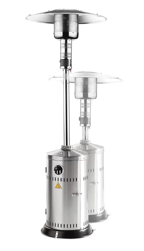
 PATIO HEATER
272602, 272701
You should read this user manual carefully before using the appliance.
Keep these instructions with the appliance.
Use outdoors only.
| Innovatielaan 6, 6745 XW De Klomp,The Netherlands www.hendi.eu |
|
||||||
| Item | 272602 Patio Heater | PIN : 0063CO7365 | |||||
| Country | NL/DE/AT/CH | BE/FR/LU/GB/IE/GR/IT | AT/CH/HR | RO/IT/HU | CZ/SK | PL | |
| Power | [HS] 12,5 kW | [HS] 10 kW | [HS] 13,5 kW | [HS] 9 kW | [HS] 10 kW | [HS] 12 kW | |
| Category | I3P | I3P | I3B/P | I3B/P | I3+ | I3B/P | |
| Consumption | 909 g/h | 715 g/h | 982 g/h | 643 g/h | G30: 728 g/h, G31: 715 g/h |
873 g/h | |
| Set up | G31-50 mbar | G31-37 mbar | G30/31-50 mbar |
G30/31-30 mbar |
G30-28-30 mbar, G31-37 mbar |
G30/31-37 mbar |
|
| Serial no. | |||||||
| Innovatielaan 6, 6745 XW De Klomp,The Netherlands www.hendi.eu |
|
||||||
| Item | 272601 Patio Heater | PIN : 0063CO7365 | |||||
| Country | NL/DE/AT/CH | BE/FR/LU/GB/IE/GR/IT | AT/CH/HR | RO/IT/HU | CZ/SK | PL | |
| Power | [HS] 12,5 kW | [HS] 10 kW | [HS] 13,5 kW | [HS] 9 kW | [HS] 10 kW | [HS] 12 kW | |
| Category | I3P | I3P | I3B/P | I3B/P | I3+ | I3B/P | |
| Consumption | 909 g/h | 715 g/h | 982 g/h | 643 g/h | G30: 728 g/h, G31: 715 g/h |
873 g/h | |
| Set up | G31-50 mbar | G31-37 mbar | G30/31-50 mbar |
G30/31-30 mbar |
G30-28-30 mbar, G31-37 mbar |
G30/31-37 mbar |
|
| Serial no. | |||||||
Dear Customer,
Thank you for purchasing this Hendi appliance. Please read this manual carefully before connecting the appliance in order to prevent damage due to incorrect use. Read the safety regulations in particular very carefully.
Safety regulations
- This appliance must be used outdoors or in a well-ventilated area, and should not be installed or used indoors.
- Change the gas cylinder in a well-ventilated area, away from any inflammation sources.
- The cylinder must be stored outdoors or in a well-ventilated area.
- Storage this appliance indoors is permissible only if the gas cylinder is disconnected and removed from the appliance.
- Do not move this appliance when in operation, or after it has been turned off before the temperature has cooled down.
- Do not attempt to alter the appliance in any manner. Do not paint the radiant screen, control panel, or reflector.
- Do not obstruct the ventilation holes of the cylinder housing.
- The appliance must be installed and the gas cylinder stored in accordance with local gas fitting regulations.
- Shut off the valve at the gas cylinder or the regulator before moving the appliance.
- Use only the type of gas specified by the manufacturer.
- Repairs should be done by a qualified person.
- In case of a violent wind, particular attention must be taken to the tilting of the appliance.
- Check that the regulator seal is correctly fitted and able to fulfill its function.
- Close the gas supply at the valve of the gas cylinder or the regulator after use.
- Do not use this appliance until all connections have been leak tested.
- In the event of gas leakage, the appliance shall not be used or if alight, the gas supply shall be shut off and the appliance shall be investigated and rectified before it is used again.
- Checking the tubing or the flexible hose per month and each time the cylinder is changed.
- The tubing or the flexible hose must be changed within the prescribed intervals or within one year. The flexible hose should not be extended to 1.5m according to standard EN16436:2014.
- The hose assembly must be replaced prior to the appliance being put into operation if there is evidence of excessive abrasion or wear, or if the hose is damaged, and that the replacement hose assembly shall be that specified by the manufacturer.
- The heater should be inspected before use and at least annually by a qualified service person. More frequent cleaning may be required as necessary. It is imperative that the control compartment, burners, and circulating air passageways of the appliance be kept clean.
- Shut off and check the heater immediately if any of the following conditions exist:
*The smell of gas in conjunction with extreme yellow tipping of the burner flames.
*Heater does not reach a proper temperature. A temperature less than 5ºC will cause restricted heat flow and the appliance will not work properly.
*The appliance starts making popping noises during use (a slight popping noise is normal when the appliance is extinguished). - The regulator & hose assembly must be located out of pathways where people may trip over it or in an area where the hose will not be subject to accidental damage.
- Any guard or other protective device removed for servicing the heater must be replaced before operating the heater.
- Children and adults should be warned of the hazards of high surface temperatures and should stay away to avoid burns or clothing ignition.
- Young children and pets should be carefully supervised when they are in the area of the heater.
- Clothing or other flammable materials should not be hung from the appliance or placed on or near the appliance.
- Do not place articles on or against this appliance. Certain material or items when stored under or near this appliance will be subjected to radiant heat and could be seriously damaged.
- Do not use or store flammable materials near this appliance.
- Do not spray aerosols in the vicinity of this appliance while it is in operation.
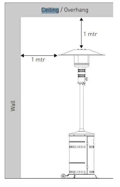
- Always maintain at least 0.9m clearance from combustible materials.
- Always position the appliance on a firm level surface. An amply ventilated area must have a minimum of 25% of the surface area open. The surface area is the sum of the surface of the wall.
- The injector in this appliance is not removable and the injector is only assembled by the manufacture. This appliance is forbidden to convert from one gas pressure to another pressure.
- Do not connect the gas cylinder directly to the appliance without a regulator.
- The gas cylinder must be fixed by the cylinder belt, which is inside the housing, while installation.
Intended use
- The device is intended for professional use and can be operated only by qualified personnel.
- The appliance is designed only for heating outdoors or well-ventilated areas. Any other use may lead to damage to the appliance or personal injury.
- Operating the appliance for any other purpose shall be deemed a misuse of the device. The user shall be solely liable for improper use of the device.
Part List
Assembly parts supplied:
- 5pcs bolts M5 x 12 and 5pcs washers M5 for the rear panel of housing and base.
- 5pcs bolts M5 x 12 and 5pcs washers M5 for the rear panel of housing and housing lid.
- 3pcs bolts M5 x 12 and 3pcs washers M5 for connection of post assembly.
- 4pcs bolts M6 x 12 and 4pcs washers M6 for the post and housing lid.
- 9pcs bolts M6 x 8, 12pcs wing nuts M6 and 12pcs washers M6 for a reflector.
- 3pcs bolts M5 x 10 and 3pcs washers M5 for main burner and the post.
- 6pcs bolts M5 x 12 and 6pcs washers M5 for base stands and base.
- 2pcs bolts M8 x 12, 4pcs washers M8, and 2pcs M8 nuts for wheels assembly.
Patio heater part:
| Item No | Description | |
| 1 | Reflector assembly | |
| 2 | Burner screen | |
| 3 | Lower tray of the burner | |
| 4 | The lower screen cone assembly | |
| 5 | Post assembly | |
| 6 | Housing lid | |
| 7 | The rear panel of the housing | |
| 8 | Wheel | |
| 9 | Base | |
| 10 | Door | |
| 11 | Hinge | |
| 12 | Assembly Bolts M5x10 | |
| 13 | Washers M5 | |
| 14 | Bolts M6x8 | |
| 15 | Wing Nut M6 | |
| 16 | Lock | |
| 17 | Plastic cover | |
| 18 | Inner pipe | |
| 19 | Igniter | |
| 20 | Assembly bolts M5x12 | |
| 21 | Washer M6 | |
| 22 | Bolts M8x12 | |
| 23 | Washer M8 | |
| 24 | Nut M8 | |
| 25 | Bolts M6x12 |
Patio heater assembly
Assembly instructions
- Screwdriver / Adjustable Spanners / Wrenches
- Leak Detection Solution one part detergent and three parts water
- Before assembly, make sure all protection packing material must be moved.
- Assembling all nuts and bolts loosely at first. Tighten all connections after completion of assembly. This eases your work and increases the stability of your appliance.
- Small deviations in equipment may occur. This is no lack of quality but is subject to improvements.STEP
SETP 1: Screw rear panel of housing to the base with 5pcs bolts M5 x 12 and 5pcs washer. (Detail Abb. A)
SETP 2: Push the housing lid over a rear panel of housing and place it onto a rear panel of the housing. Screw together the housing lid and rear panel of housing with 5pcs bolts M5x12 and 5pcs washers. (Detail Abb. B)
SETP 3: Fix the post assembly upwards onto the housing lid with 4pcs bolts M6 x 12 and 4pcs washers, then put plastic cover through the post. Detail Abb. D-1)Connect the post assembly with 3pcs M5x12 screw and 3pcs flat washer. (Detail Abb. D-2)
SETP 4: Fix one piece reflector to the central dome with 1pc bolt M6*8, 1pcs cap screw, 1pcs flat washer firstly. (Detail Abb. E-1). Connect the second reflector part to the first one and central dome with 3pc bolt M6x8, 3pcs cap screw, 3pcs flat washer later. (Detail Abb. E-2). Fix the third reflector part with 5pc bolt M6x8, 5pcs cap screw, 5pcs flat washer at last. (Detail Abb. E-3)
SETP 5: Tighten the inner gas pipe to the main burner (See Figure 1), Then fix the main burner to the pot with 3 bolts M5x10 and 3pcs washers. (Detail Abb. F)
NOTE: DO NOT OVERTIGHTEN! REFER TO LEAK TESTING ON PAGE5.
SETP 6: Fix the door to the housing. (See Figure 2 and Detail Abb. G)
| Detail A |
Detail E |
| Detail B |
Detail F |
Detail C |
Detail G |
Detail D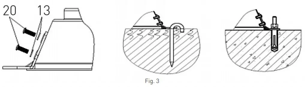 |
Detail H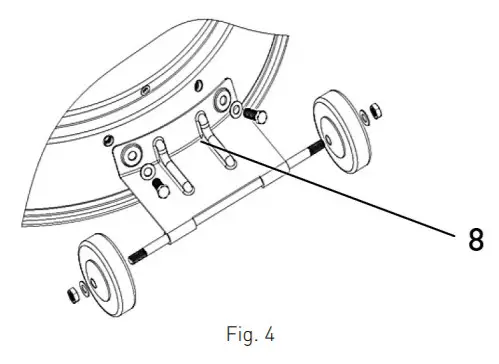 |
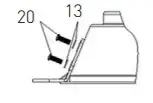
Optional base stand
Base stand assembly parts: 6pcs bolts M5 x 12 and 6pcs washers for base stands and base.
Attach 3pcs stands to the base. Buy suitable hook bolts or rawlbolts from your local market to insert them into the ground or floor through base stand holes for this appliance’s stability. (See Figure 3)
Optional wheels
Wheels assembly parts: 2pcs bolts, 4pcs washers, and 2pcs nuts for wheels assembly. Collect wheels parts together and fix wheels to the base. (See Figure 4)
Operating instructions
Before first use and after every gas cylinder change, the gas delivery system must be purged of air before igniting!
To do this, turn the control knob counter-clockwise to the pilot setting. Press knob in and hold for 3 minutes before attempting ignition.
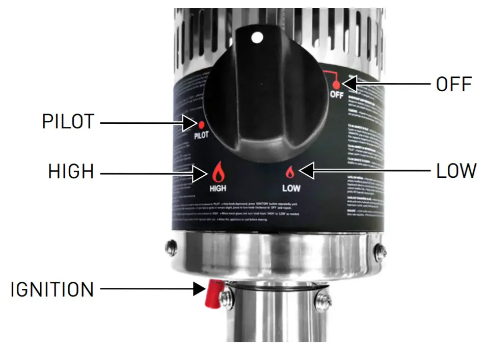
To light the pilot
- Check all connections prior to each use.
- Turn on the main gas supply.
- Press to turn control knob counter-clockwise to PILOT, see right photo.
- Hold knob depressed, press IGNITION button repeatedly until pilot flame is lit, then continue to hold the knob depressed for 10 seconds until the pilot remains it after releasing knob.
- If the pilot fails to ignite or alight, press to turn the knob clockwise to OFF and repeat.
To light the patio heater
- The pilot should be lit and the knob set to PILOT.
- Press the knob 3mm and turn anti-clockwise to HIGH.
- When mesh glows lit, turn the knob clockwise from HIGH to LOW as needed.
Note: The burner may be noisy when initially turned on. To eliminate excessive noise from the burner, turn the control knob to the pilot position. Then, turn the knob to the level of heat desired.
Re-lighting
Note: For your safety, Control Knob cannot be turned OFF without first depressing Control Knob in PILOT position and then rotating it to OFF.
- Turn Control Knob to OFF.
- Wait at least 5 minutes, to let the gas dissipate, before attempting to re-light the pilot.
- Repeat the “Lighting” steps
To extinguish
- Hold knob depressed & turn the knob clockwise to ‘OFF’
- Close the valve of the gas cylinder or the regulator after use.
- Allow this appliance to cool before moving.
Note: After use, some discoloration of the emitter screen is normal.
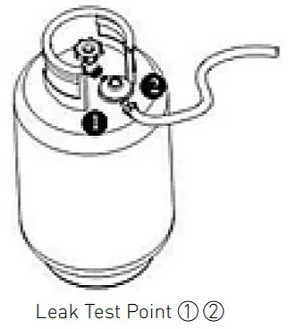
Leak testing
NEVER USE A NAKED FLAME TO CHECK FOR LEAKS. NEVER LEAK TEST WHILE SMOKING
The gas connections on this appliance are leak tested at the factory prior to shipment. This appliance needs to be periodically checked for leaks and an immediate check is required if the smell of gas is detected.
- Make a soap solution using 1 part of liquid dish-washing soap to 3 parts water. The soap solution can be applied with a soap bottle, brush, or rag to the leak-tested points shown in the figure above.
- The valve of the gas cylinder should be in the OFF position at this point of the leak test. Once the soapy solution is applied to the gas connections, the valve of the gas cylinder needs to be turned to the ON position.
- Soap bubbles will begin to form in the soapy solution if a leak is present.
- In case of a leak, turn off the gas supply. Tighten any leaking fittings, then turn the gas supply on and recheck.
Gas requirements
- The pressure regulator and hose assembly to be used must conform to local standard codes.
- Never use a gas cylinder with a damaged body, valve, collar, or foot ring.
- A dented or rusty gas tank may be hazardous and should be checked out by a gas supplier.
- Never connect this appliance to an unregulated gas source.
- When the appliance is not in use, turn the gas cylinder OFF.
- Always perform a leak test on gas connections whenever a cylinder is connected. If bubbles form in the leak test solution, do not use it. Never use a flame to test for leaks.
Connecting to a gas cylinder
- Recommend to use a 9kg gas cylinder or refer to your gas supplier for suitable gas cylinders.
- The approved gas regulator is used according to appliances categories and countries listed in the data plate. The approved flexible hose would be changed when the national conditions require it & consult the local regulations, these may differ.
- Warning: assembly of the tubing must be conducted by some qualified tuber of destination countries.
- Refer to your gas supplier for instructions on the use of your gas cylinder.
- Only change gas cylinders outdoors or in a well-ventilated area away from naked flames and any other source of ignition.
- The gas cylinder must always be used in an upright position.
- Close the heater control knob by turning fully clockwise.
- Close the gas cylinder tap and then attach the regulator onto the gas cylinder.
- Tighten all connections firmly and with a spanner where appropriate. The cylinder should be located on the cylinder base.
- The gas cylinder must be fixed by the cylinder belt, which is inside the housing, while installation.
- Check for leaks at all joints using soapy water. If a leak is found, tighten the joint and then re-test.
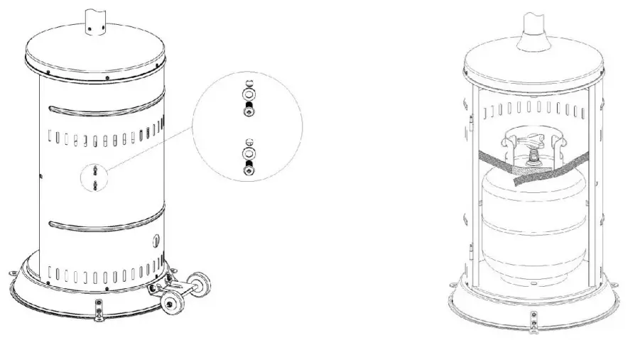
Securing the gas cylinder
- Fix both brackets of Velcro tapes onto the base using 4pcs M6*12 bolts, M6 washer, and M6nuts.
- Position a gas cylinder inside the tank housing.
- Connect the gas cylinder with a regulator. Please refer to the instructions attached with the regulator on how to connect a regulator with the gas cylinder.
- Stick Velcro tapes together as the above photo illustrated. The tapes must be in a proper tightness for the gas cylinder.
Caution: Please take care that the Velcro tapes. DO NOT strain the regulator assembly.
Important safety rules
For use outdoors or in amply ventilated areas. An amply ventilated area must have a minimum of 25% of the surface area open.
The surface area is the sum of the surface of the wall.
The use of this appliance in enclosed areas can be dangerous and is PROHIBITED.
Children and adults should be aware of the high operating temperatures of areas above the post when operating this heater. Children should be carefully supervised when in the vicinity of the heater.
NEVER hang anything, including clothes or any other flammable items, on this heater.
DO NOT operate this heater unless it is fully assembled ith its reflector in place. Respect the minimum clearances from combustible materials.
The length of the gas hose may not exceed 1,5 meters.
Maintenance
To enjoy years of outstanding performance from your heater, make sure you perform the following maintenance activities on a regular basis:
- Keep exterior surfaces clean.
- Use warm soapy water for cleaning. Never use flammable or corrosive cleaning agents.
- While washing your unit, be sure to keep the area around the burner and pilot assembly dry at all times. If the gas control is exposed to water in
any way, DO NOT try to use it. It must be replaced. - Airflow must be unobstructed. Keep controls, burner, and circulation air passageways clean. Signs of possible blockage include:
- Gas odor with extreme yellow tipping of flame.
- The heater does NOT reach the desired temperature.
- The heater glow is excessively uneven.
- The heater makes popping noises.
- Spiders and insects can nest in burner or orifices.
This dangerous condition can damage the heater and render it unsafe for use. Clean burner holes by using a heavy-duty pipe cleaner. Compressed air may help clear away smaller particles. - Carbon deposits may create a fire hazard. If any carbon deposits develop, clean the dome and engine with warm soapy water.
Note: in a salt-air environment (such as near the sea), corrosion occurs more quickly than normal. Frequently check the corroded areas and repair them promptly.
Servicing
- Please consult your local dealer for servicing this appliance and replacement of its parts. The servicing of the appliance shall be carried out only by authorised personnel.
- Caution: do not use unauthorized parts or components for this appliance, only use original equipment replacement parts and components. The use of unauthorized parts or components will void the warranty and can create an unsafe condition.
Storage
Between uses:
Turn control knob OFF
Turn gas cylinder OFF
Store the Heater upright in an area sheltered from direct contact with inclement weather (such as rain, sleet, hail, snow, dust and debris).
If desired, cover to protect exterior surfaces and to prevent build-up in air passages.
Note: Wait until the heater is cool before covering.
During periods of extended inactivity or when transporting:
Turn control knob OFF.
Disconnect gas cylinder and move to a secure, well-ventilated location outdoors. DO NOT store in a location that will exceed 50°C. Store heater right in an area sheltered from direct contact with inclement weather (such as rain, sleet, hail, snow, dust, and debris).
If desired, cover the heater to protect exterior surfaces and to prevent build-up in air passages.
Note: Wait until the heater is cool before covering
CAUTION: DO NOT USE UNAUTHORISED PARTS OR COMPONENTS FOR THIS APPLIANCE. ONLY USE ORIGINAL EQUIPMENT REPLACEMENT PARTS AND COMPONENTS.
To retract the heater (272701 only)
Retracting the heater makes storage much easier. Loose the plastic screw (17) properly. Pull up the main post vertically until it encounters the housing lid. Turn the main post clockwise and lower it until it has reached the desired level. To lock the main post on the desired level pull up the main post just
a little and turn it counterclockwise. Then lower it until the main post stands on its screws. Tighten the plastic screw to keep the heater stable.
Note: Mind your head. Wait until the heater is cool before retracting.
Troubleshooting
| PROBLEM | AND THIS CONDITION EXISTS | THEN DO THIS |
| Pilot won’t light | The cylinder valve is closed | Open valve |
| Blockage in orifice or pilot tube | Clean or replace orifice or pilot tube. | |
| Air in the gas line | Open gas tine and bleed it (pressing control knob in) for not more than 1-2 minutes or until you smell gas. | |
| Low gas pressure | Replace propane gas (disposable) cylinder with a new cylinder | |
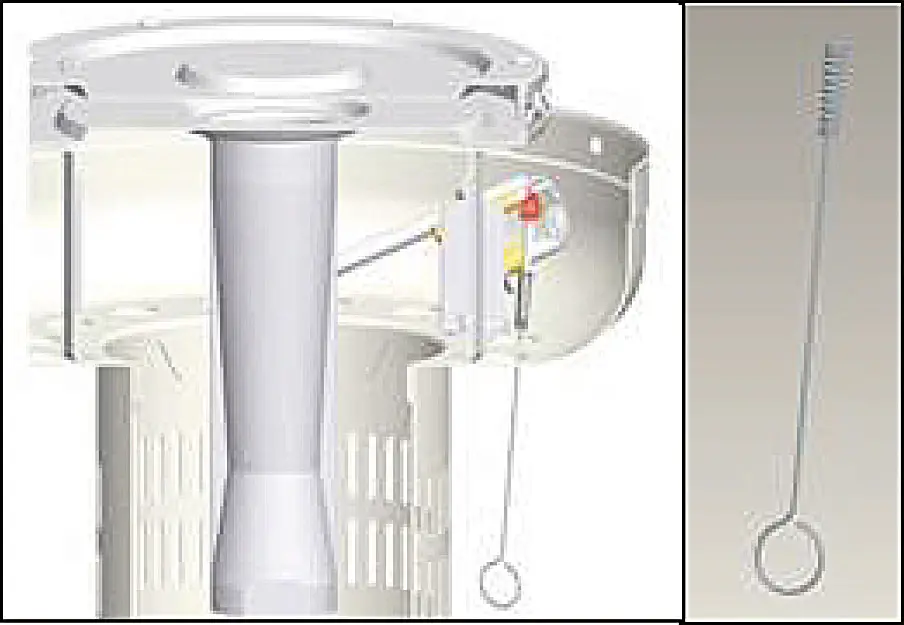
| Igniter fails | Use a match to light pilot (with match holder, see picture•); obtain new igniter and replace | |
| The pilot won’t stay lit | Dirt build-up around pilot | Clean dirt from around pilot |
| The connection between gas valve and pilot assembly is loose | Tighten connection and perform a leak test | |
| The thermocouple is not operating correctly | Replace thermocouple | |
| Burner won’t tight | Gas pressure is low | Replace propane gas (disposable) cylinder with a new cylinder |
| Blockage in orifice | Clear blockage | |
| The control knob is not in the “ON” position | Turn the control knob to “ON” position | |
| The burner flame is low Note: Do not operate heater below 5°C (40°F) |
Gas pressure is low | Replace propane gas (disposable) cylinder with a new cylinder |
| Outdoor temperature is greater than 406F and tank is less than 25% full | Replace propane gas (disposable) cylinder with a new cylinder | |
| The supply hose is bent or kinked | Straighten hose and perform leak test on the hose | |
| The control knob is full ” ON” | Turn the control knob to ” OFF”, let cool to room temperature, and check burner and orifices for blockage | |
| Emitter glows uneven Note: Bottom 1 inch of emitter normally does not glow |
Gas pressure is low | Replace propane gas (disposable) cylinder with a new cylinder |
| The base is not on a level surface | Place heater on a level surface | |
| Heater is level | Clean burner | |
| Carbon build-up | Dirt or film on reflector and emitter | Clean reflector and emitter |
| Thick black smoke | Blockage in burner | Turn the control knob to “OFF”, let cool to room temperature and remove blockage, and clean the burner inside and outside. |

If for some reasons your ignition fails to deliver a spark, the heater can be started by inserting a lit match using supplied match holder through the burner hole (see left photo) while pushing the control knob in the “PILOT” position.
IN THE EVENT OF ANY PROBLEM, PLEASE ALWAYS CONSULT YOUR LOCAL DEALER.
Warranty
Any defect affecting the functionality of the appliance which becomes apparent within one year after purchase will be repaired by free repair or replacement provided the appliance has been used and maintained in accordance with the instructions and has not been abused or misused in any way. Your statutory rights are not affected. If the appliance is claimed under warranty, a state where and when it was purchased and include proof of purchase (e.g. receipt).
In line with our policy of continuous product development, we reserve the right to change the product, packaging, and documentation specifications
without notice.
Discarding & Environment
When decommissioning the appliance, the product must not be disposed of with other household waste. Instead, it is your responsibility to dispose to your waste equipment by handing it over to a designated collection point. Failure to follow this rule may be penalized in accordance with applicable regulations on waste disposal. The separate collection and recycling of your waste equipment at the time of disposal will help conserve natural resources and ensure that it is recycled in a manner that protects human health and the environment. For more information about where you an drop off your waste for recycling, please contact your local waste collection company. The manufacturers and importers do not take responsibility or recycling, treatment, and ecological disposal, either directly or through a public system.
Hendi B.V.
Innovatielaan 6
6745 XW De Klomp, The Netherlands
Tel: +31 317 681 040
Email: [email protected]
PKS Hendi South East Europe SA
5 Metsovou Str. 18346 Moschato, Athens, Greece
Tel: +30 210 4839700
Email: [email protected]
Find Hendi on internet:
www.hendi.eu
www.facebook.com/HendiToolsforChefs
www.linkedin.com/company/hendi-food-service-equipment-b.v.
www.youtube.com/HendiEquipment
– Changes, printing and typesetting errors reserved.
© 2021 Hendi B.V. De Klomp – The Netherlands